


42V
Manufacturer reserves the right to discontinue, or change at any time, specifications or designs without notice and without incurring obligations.
Catalog No. 04-53420004-01 Printed in U.S.A. Form 42-3SI Pg 1 12-09 Replaces: 42-2SI
Installation, Start-Up and Service
Instructions
CONTENTS
Page
SAFETY CONSIDERATIONS . . . . . . . . . . . . . . . . . . . . . . 1
INTRODUCTION . . . . . . . . . . . . . . . . . . . . . . . . . . . . . . . . . . 1
PHYSICAL DATA . . . . . . . . . . . . . . . . . . . . . . . . . . . . . . . 1-3
PRE-INSTALLATION. . . . . . . . . . . . . . . . . . . . . . . . . . . 3-39
Unpack and Inspect Units . . . . . . . . . . . . . . . . . . . . . . . . 3
Protect Units From Damage . . . . . . . . . . . . . . . . . . . . . . 3
Prepare Jobsite for Unit Installation. . . . . . . . . . . . . . 3
Identify and Prepare Units. . . . . . . . . . . . . . . . . . . . . . . . 3
INSTALLATION . . . . . . . . . . . . . . . . . . . . . . . . . . . . . . . 40-67
Step 1 — Place Units in Position . . . . . . . . . . . . . . . . 40
• 42C UNITS
• 42V UNITS
• 42D UNITS
• 42S UNITS
Step 2 — Make Piping Connections . . . . . . . . . . . . . 42
• VALVE PACKAGES
• 42C,D,V DRAIN CONNECTIONS
• 42C,D,V WATER SUPPLY/RETURN
CONNECTIONS
• 42C,D,V STEAM CONNECTIONS
• 42C,D,V DIRECT EXPANSION (DX) REFRIGERANT
PIPING
• TEST AND INSULATE
Step 3 — Make Electrical Connections . . . . . . . . . . 55
• STANDARD WIRING PACKAGES
Step 4 — Make Duct Connections . . . . . . . . . . . . . . . 66
Step 5 — Frame and Finish Unit. . . . . . . . . . . . . . . . . 66
Step 6 — Cut out Openings for Grilles and
Thermostats . . . . . . . . . . . . . . . . . . . . . . . . . . . . . . . . . . 67
Step 7 — Make Final Preparations. . . . . . . . . . . . . . . 67
START-UP . . . . . . . . . . . . . . . . . . . . . . . . . . . . . . . . . . . . . . . 67
SERVICE . . . . . . . . . . . . . . . . . . . . . . . . . . . . . . . . . . . . . .67,68
Excessive Condensation on Unit. . . . . . . . . . . . . . . . 67
To Clean Coil . . . . . . . . . . . . . . . . . . . . . . . . . . . . . . . . . . . . 67
Coil Air Vent (Manual or Automatic) . . . . . . . . . . . . . 67
Check Drain . . . . . . . . . . . . . . . . . . . . . . . . . . . . . . . . . . . . . 67
Fan Motor Bearings . . . . . . . . . . . . . . . . . . . . . . . . . . . . . 67
Clean Fan Wheel . . . . . . . . . . . . . . . . . . . . . . . . . . . . . . . . 68
Clean Electric Heater. . . . . . . . . . . . . . . . . . . . . . . . . . . . 68
Clean or Replace Air Filters . . . . . . . . . . . . . . . . . . . . . 68
Warranty . . . . . . . . . . . . . . . . . . . . . . . . . . . . . . . . . . . . . . . . 68
START-UP CHECKLIST FOR 42C,D,S,V SERIES
FAN COIL AIR CONDITIONERS. . . . . . . . CL-1, CL-2
SAFETY CONSIDERATIONS
Installation of this unit can be hazardous due to electrical com-
ponents and equipment location (such as a ceiling or elevated
structure). Only trained, qualified installers and service
mechanics should install and service this equipment.
When installing this unit, observe precautions in the literature,
labels attached to the equipment, and any other safety precau-
tions that apply.
• Follow all safety codes.
• Wear safety glasses and work gloves.
• Use care in handling and installing this accessory.
INTRODUCTION
This document contains general installation instructions for
the 42C,D,S,V unit fan coils. Refer to the unit-wiring diagram
installed on the blower housing or specific manufacturer litera-
ture for any other type of factory-mounted controls.
See drawings for unit configurations, dimensions, clearances,
and pipe connections. Refer to unit wiring label for all electrical
connections; follow NEC (National Electrical Code) and local
codes.
PHYSICAL DATA
Component weight data, shipping weights, and filter data of
the 42C,D,S,V units are provided in Tables 1-4.
WARNING
ELECTRIC SHOCK HAZARD To avoid the possibility of
electrical shock, open and tag all service switches before
installing this equipment.
42C,D,S,V Series
Fan Coil Air Conditioners
2
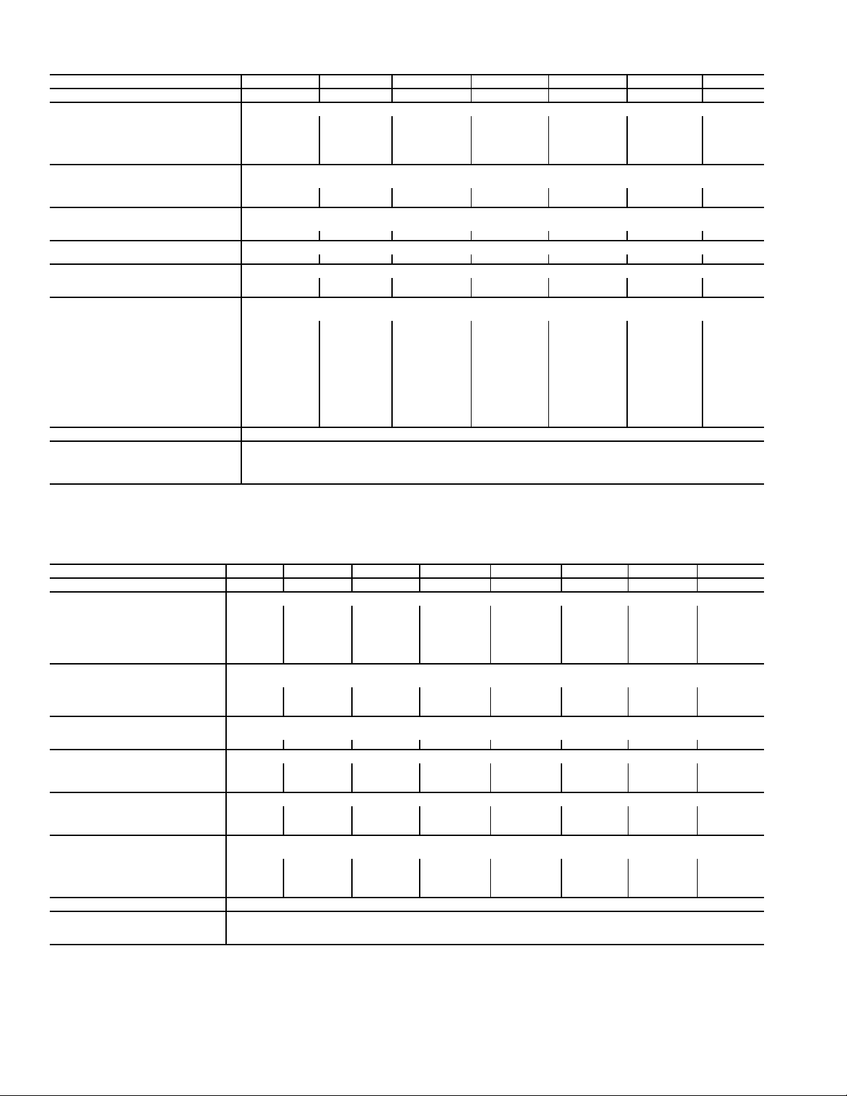
Table 1 — Physical Data — 42C Series Units
*Calculate operating weight of unit: shipping weight + coil water weight x
number of coil rows.
†42CF applies to sizes 04 to 10.
**Filter size for return-air grille location.
††Filter size if located in return-air plenum.
***With electric heater and bottom return, the 42CF unit filter width increases
from 12
3
/
4
to 16
3
/
4
.
Table 2 — Physical Data — 42V Series Units
*Calculate operating weight of unit: shipping weight + coil water weight x
number of coil rows.
†Available in sizes 02-06.
UNIT SIZE 42C 02 03 04 06 08 10 12
NOMINAL AIRFLOW (cfm) 200 300 400 600 800 1000 1200
SHIPPING WEIGHT (lb)*
42CA 36 39 49 59 64 95 107
42CE 55 60 70 82 95 135 154
42CF — — 84 97 110 163 —
42CG 98 118 126 168 176 215 245
42CK 115 120 135 150 155 227 241
COIL WATER WEIGHT
(Approx lb per row of coil)
42CA, CE, CG, CK 0.7 0.8 1.0 1.4 1.7 2.3 2.7
42CF — — 1.02 1.42 1.71 2.32 —
COILS
FPI 10 fins/inch
Coil Face Area (sq ft)† 0.8 1.1 1.4 1.9 2.3 3.2 3.7
MOTOR (qty)
42C Series 111 1 122
BLOWER (qty)
42CA, CE, CG, CK 112 2 244
42CF —— 2 2 2 4—
FILTERS
Nominal Size (in.) (1-in. thick)
42CA** 10 x 24 10 x 28 10 x 32 10 x 42 10 x 42 10 x 54 10 x 64
42CE†† 10 x 18 10 x 22 10 x 28 10 x 33 10 x 40 10 x 54 10 x 62
42CF††*** ——12
3
/
4
x 28 12
3
/
4
x 33 12
3
/
4
x 40 12
3
/
4
x 54 —
42CG
Bottom Return 10 x 23
1
/
2
10 x 28 10 x 32
1
/
2
10 x 37 10 x 41 10 x 54
1
/
2
10 x 63
Rear Return 8 x 23
1
/
2
8 x 28 8 x 32
1
/
2
8 x 37 8 x 41 8 x 54
1
/
2
8 x 63
42CK
Bottom Return 10 x 28 10 x 28 10 x 33 10 x 45 10 x 45 10 x 62 10 x 62
Rear Return 7 x 21 7 x 21 7 x 27 7 x 38 7 x 38 7 x 52 7 x 52
Rear Return with Duct Collar 6 x 18
3
/
4
6 x 18
3
/
4
6 x 24
3
/
4
6 x 35
3
/
4
6 x 35
3
/
4
6 x 49
3
/
4
6 x 49
3
/
4
Qty 111 1 111
SUPPLY DUCT COLLAR 1-in.
PIPING CONNECTIONS (Sweat) (in.)
Coil Outlet and Inlet
5
/
8
OD
Drain Connection
7
/
8
OD
Tell-Tale Drain
5
/
8
OD
UNIT SIZE 42V 01 02 03 04 06 08 10 12
NOMINAL AIRFLOW (cfm) 150 200 300 400 600 800 1000 1200
SHIPPING WEIGHT (lb)*
42VA — 65 80 90 112 115 140 170
42VB — 89 95 116 134 137 169 192
42VC — 50 60 72 110 — — —
42VE — 72 100 108 154 — — —
42VF — 92 98 122 141 144 178 205
42VG 40 — 74 — — — — —
COIL WATER WEIGHT
(Approx lb per row of coil)
42VA, VB, VC†, VF — 0.7 0.8 1.0 1.4 1.7 2.3 2.7
42VE — 0.9 1.2 1.6 2.3 — — —
42VG 0.4 — 1.0 — — — — —
COILS
FPI 12 fins/inch
Coil Face Area (sq ft) 0.8 0.8 1.1 1.4 1.9 2.3 3.2 3.7
MOTOR (qty)
42VA, VB, VF —11 1 1122
42VC, VE —1 1 1 2 — — —
42VG 1— 2 — — — — —
BLOWER (qty)
42VA, VB, VF —11 2 2244
42VC, VE —2 2 2 4 — — —
42VG 1— 2 — — — — —
FILTERS
Nominal Size (in.) (1-in. thick)
42VA, VB, VF —7
3
/
4
x 21
3
/
4
7
3
/
4
x 25
3
/
4
7
3
/
4
x 31
3
/
4
7
3
/
4
x 41
3
/
4
7
3
/
4
x 43
3
/
4
7
3
/
4
x 57
3
/
4
7
3
/
4
x 65
3
/
4
42VC, VE —7 x 21
3
/
4
7 x 26
3
/
4
7 x 34
3
/
4
7 x 48
3
/
4
———
42VG 10 x 14
1
/
2
— 10 x 28 — — — — —
Qty 111 1 1111
SUPPLY DUCT COLLAR 1-in.
PIPING CONNECTIONS (Sweat) (in.)
Coil Outlet and Inlet
5
/
8
OD
Drain Connection
3
/
4
MPT
3
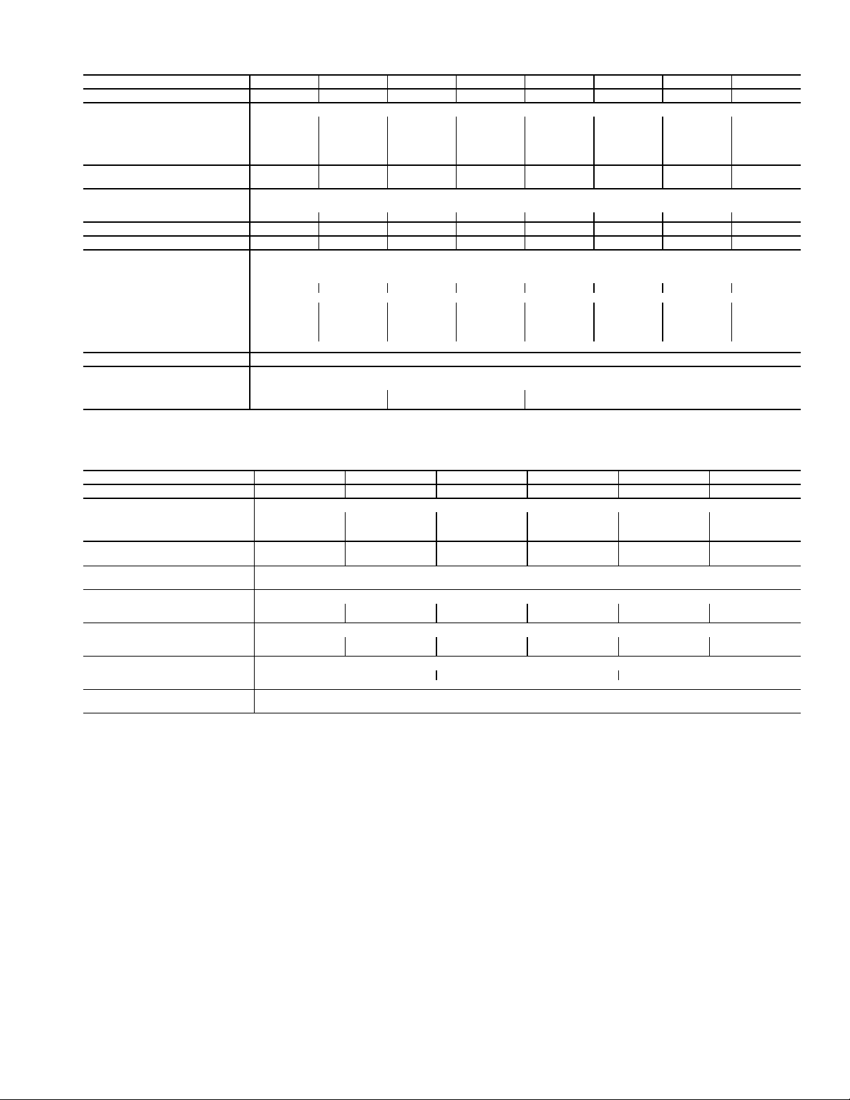
Table 3 — Physical Data — 42D Series Units
*Calculate Operating Weight of unit: Shipping Weight + Coil Water Weight x Number of Coil Rows.
Table 4 — Physical Data — 42S Series Units
*Calculate Operating Weight of Unit: Shipping Weight + Coil Water Weight x Number of Coil Rows.
†42SJ units require two filters.
PRE-INSTALLATION
Unpack and Inspect Units —
Remove shipping wraps
from all units. Check the shipment against shipping order.
Make sure that furnished only items, such as thermostat,
grilles, etc., are accounted for, whether packaged separately or
shipped at a later date. If shipment is damaged or incomplete,
file claim with transportation company and advise Carrier im-
mediately.
Protect Units from Damage — The equipment must
always be properly supported. Temporary supports used during
installation or service must be adequate to hold the equipment
securely. Equipment should always be stored in the proper ori-
entation as marked on the carton. To maintain warranty, protect
units against adverse weather, theft, vandalism, and debris on
jobsite. Equipment covered in this manual is not suitable for
outdoor installations. Do not allow foreign material to fall into
drain pan. Prevent dust and debris from being deposited on mo-
tor and fan wheels. Manufacturer's warranty is void if foreign
material is allowed to be deposited on the motor or blower
wheels of any unit.
Prepare Jobsite for Unit Installation — To sav e
time and to reduce the possibility of costly errors, set up a com-
plete sample installation in a typical room at jobsite. Check all
critical dimensions such as pipe, wire, and duct connection
requirements. Refer to job drawings and product dimension
drawings as required (see Fig. 1-36). Instruct all trades in their
part of the installation.
Identify and Prepare Units — Be sure power require-
ments match available power source. Refer to unit nameplate
and wiring diagram.
1. Check all tags on unit to determine if shipping screws are
to be removed. Remove screws as directed.
2. Rotate the fan wheel by hand to ensure that the fan is
unrestricted and can rotate freely. Check for shipping
damage and fan obstructions.
UNIT SIZE 42D 0608101214161820
NOMINAL AIRFLOW (cfm) 600 800 1000 1200 1400 1600 1800 2000
SHIPPING WEIGHT (lb)*
42DA 64 79 93 110 119 129 137 155
42DC 94 107 150 169 174 178 195 220
42DD 150 163 176 195 220 235 240 247
42DE 135 155 165 184 199 215 232 243
42DF 157 167 177 199 215 229 249 258
COIL WATER WEIGHT
(Approx lb per row of coil)
1.31.61.92.32.73.03.43.7
COILS
FPI 10 fins/inch
Coil Face Area (sq ft) 1.62.12.53.03.54.14.65.0
MOTOR (qty) 11122222
BLOWER (qty) 11122222
FILTERS
Nominal Size (in.) (1-in. thick)
42DA NA
42DC 14 x 21 14 x 26 14 x 30 14 x 35 14 x 40 14 x 45 14 x 50 14 x 54
42DD
(Front Return) 12
3
/
4
x 21 12
3
/
4
x 26 12
3
/
4
x 30 12
3
/
4
x 35 12
3
/
4
x 40 12
3
/
4
x 45 12
3
/
4
x 50 12
3
/
4
x 54
(Bottom Return) 12
3
/
4
x 21 12
3
/
4
x 25 12
3
/
4
x 29 12
3
/
4
x 34 12
3
/
4
x 39 12
3
/
4
x 44 12
3
/
4
x 49 12
3
/
4
x 53
42DE 14 x 14
3
/
4
14 x 19
3
/
4
14 x 23
3
/
4
14 x 28
3
/
4
14 x 33
3
/
4
14 x 38
3
/
4
14 x 43
3
/
4
14 x 47
3
/
4
42DF 14 x 14 14 x 20 14 x 24 14 x 28 14 x 34 14 x 38 14 x 44 14 x 48
Qty
1
SUPPLY DUCT COLLAR 1-in.
PIPING CONNECTIONS
(Sweat - 4-Row)
Inlet (in. OD)
5
/
8
7
/
8
1
1
/
8
Outlet (in. OD)
5
/
8
7
/
8
1
1
/
8
UNIT SIZE 42S 03 04 06 08 10 12
NOMINAL AIRFLOW (cfm) 300 400 600 800 1000 1200
SHIPPING WEIGHT (lb)*
42SG,SU 180 225 240 260 280 305
42SH 202 247 262 286 311 336
42SJ 360 450 480 520 560 610
COIL WATER WEIGHT
(Approx lb per row of coil) 1.6 1.6 2.3 2.3 3.1 3.1
COILS
FPI 14 fins/inch
MOTOR (qty)
42SG,SH,SU 111111
42SJ 222222
BLOWER (qty)
42SG,SH,SU 111111
42SJ 222222
FILTERS
Nominal Size (in.) (1-in. thick) 12
1
/
2
x 24
1
/
4
16
1
/
4
x 26
3
/
4
20
1
/
2
x 29
1
/
4
Qty 1†
PIPING CONNECTIONS
Inlet (in. OD)
1
/
2
4
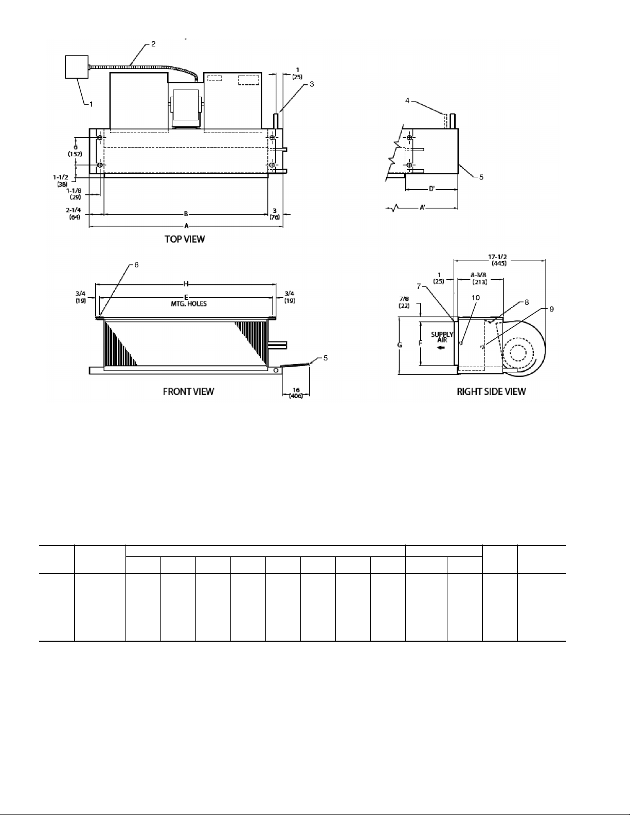
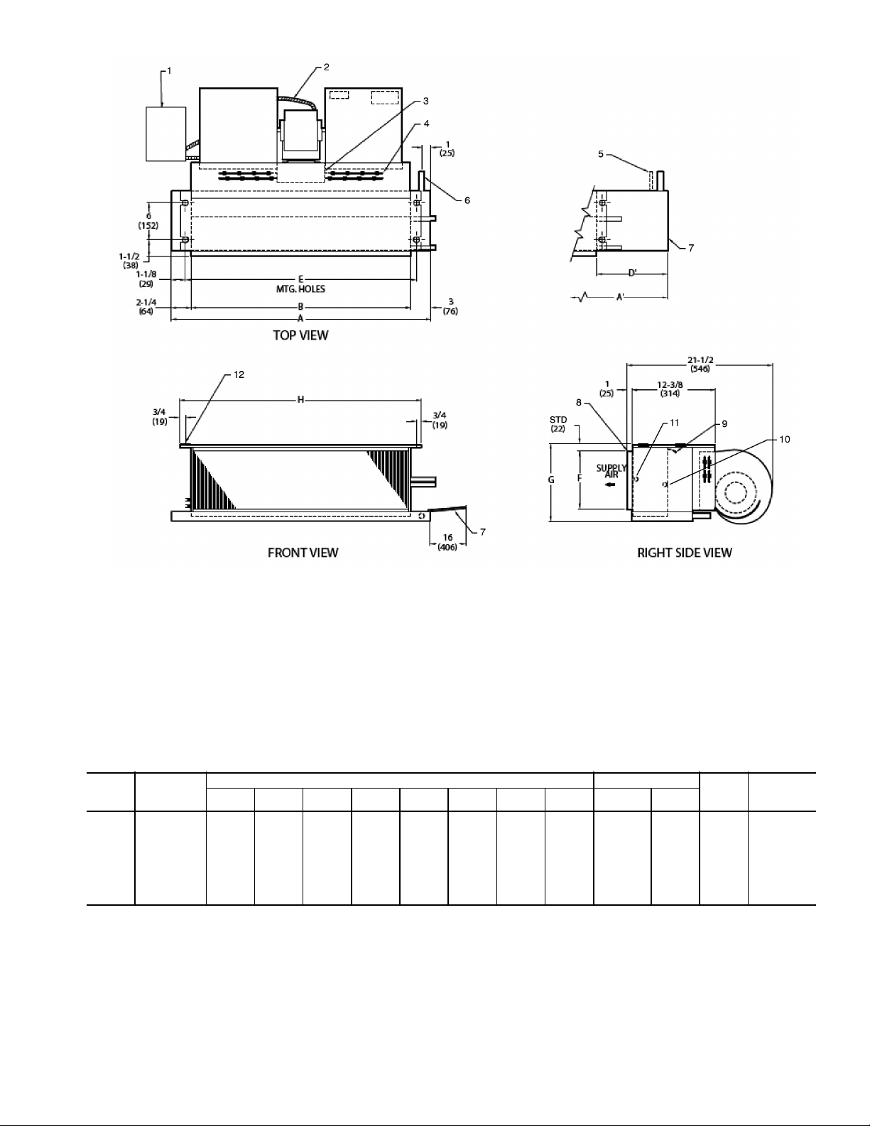
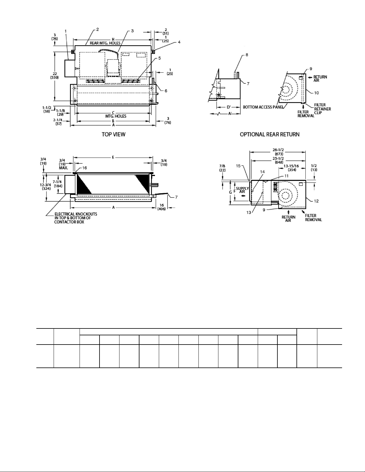
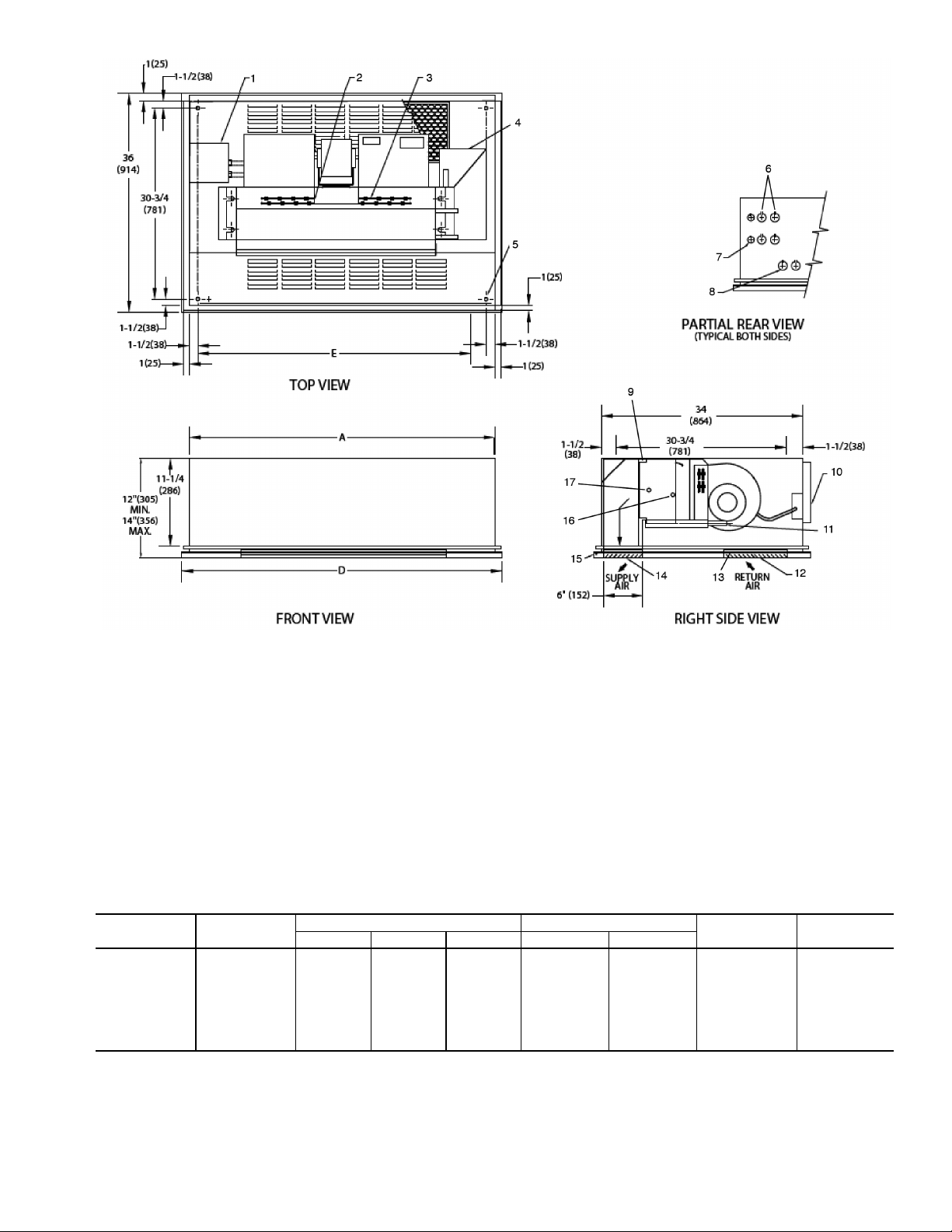
LEGEND
1—Junction Box (remote mount)
2—Flexible Metal Conduit
3—Drain Conn,
7
/
8
-in. OD
4 — Tell-Tale Drain Conn,
5
/
8
-in. OD (optional)
5—Drip Lip (optional)
6—Hanger Slots (4), Rubber Grommet
has
3
/
8
-in. Diameter Hole
7—Supply Duct Collar, 1-in.
8—Air Vent,
1
/
8
-in. MPT
9—Return Conn,
5
/
8
-in. OD
10 — Supply Conn,
5
/
8
-in. OD
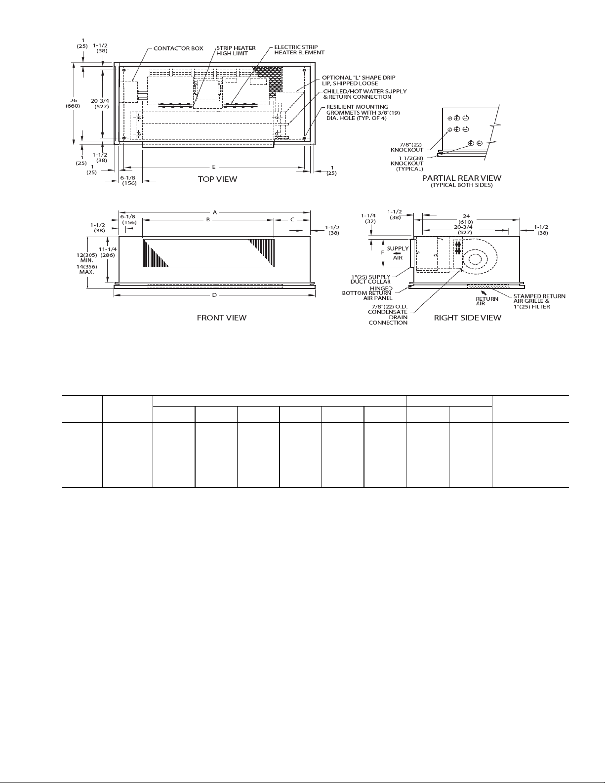
*Unit weights are based on dry coils and minimum rows. Weights exclude packaging, valves, and other components.
UNIT
SIZE
NOM
AIRFLOW
(Cfm)
DIMENSIONS (in.) QTY/UNIT FACE
AREA
(sq ft)
UNIT
WEIGHT*
(lb)
AA’BD’E F GH
Blower Motor
02 200 21
1
/
4
31
1
/
4
16 13 18
1
/
4
6
1
/
4
8
3
/
4
19
3
/
4
1 1 0.83 36
03 300 25
1
/
4
36
1
/
4
20 14 22
1
/
4
6
1
/
4
8
3
/
4
23
3
/
4
1 1 1.08 39
04 400 31
1
/
4
43
1
/
4
26 15 28
1
/
4
6
1
/
4
8
3
/
4
29
3
/
4
2 1 1.35 49
06 600 36
1
/
4
43
1
/
4
31 10 33
1
/
4
7
1
/
2
10 34
3
/
4
2 1 1.88 59
08 800 43
1
/
4
57
1
/
4
38 17 40
1
/
4
7
1
/
2
10 41
3
/
4
2 1 2.31 64
10 1000 57
1
/
4
65
1
/
4
52 11 54
1
/
4
7
1
/
2
10 55
3
/
4
4 2 3.16 95
12 1200 65
1
/
4
75
1
/
4
60 13 62
1
/
4
7
1
/
2
10 63
3
/
4
4 2 3.65 107
NOTES:
1. Right hand unit shown; left hand unit opposite. Coil connection
locations are ±
5
/
8
-in.
2. Unit sizes 02 and 03 have one motor, one blower; sizes 04
through 08 have one motor, 2 blowers; sizes 10 and 12 have
2 motors, 4 blowers.
3. Standard 3-row coil shown.
4. Overall unit dimension increases by 4 in. with optional electric
heat.
5. Not shown: 3-speed fan switch; wall plate, closed cell foam on
main drain pan.
6. Units have galvanized finish.
7. For optional coil connections, view 42CA-203-1 using the Fan Coil
Builder.
8. Dimensions shown in inches (mm).
Fig. 1 — 42CA Furred-In Horizontal Unit Dimensions
a42-4099.eps
5
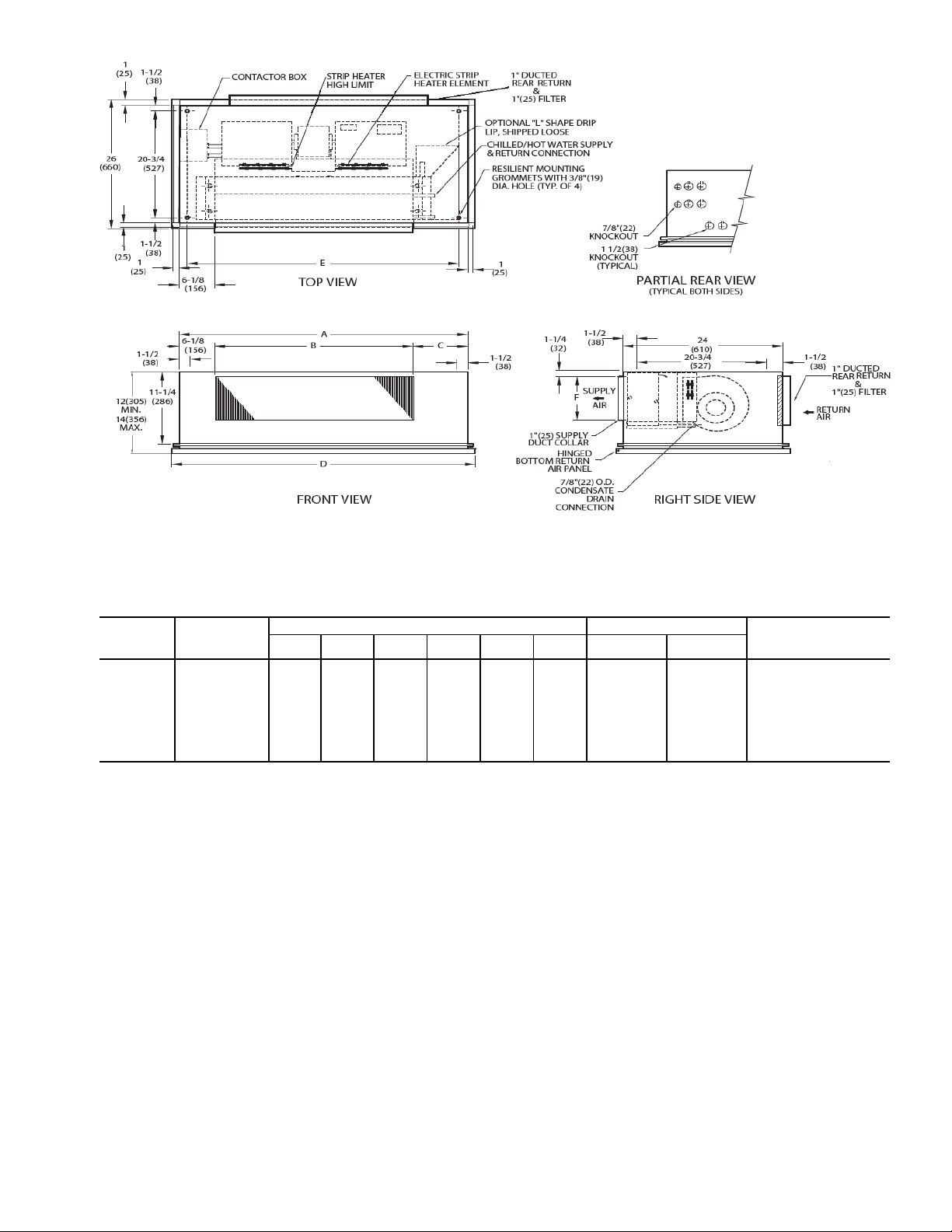
LEGEND
1—Junction Box (remote mount)
2—Flexible Metal Conduit
3 — Strip Heater High Limit
4 — Electric Strip Heater Element
5 — Tell-Tale Drain Conn,
5
/
8
-in. OD (optional)
6—Drain Conn,
7
/
8
-in. OD
7—Drip Lip (optional)
8—Supply Duct Collar, 1-in.
9—Air Vent,
1
/
8
-in. MPT
10 — Return Conn,
5
/
8
-in. OD
11 — Supply Conn,
5
/
8
-in. OD
12 — Hanger Slots (4), Rubber Grommet
has
3
/
8
-in. Diameter Hole
NOTES:
1. Right hand unit shown; left hand unit opposite. Coil connection
locations are ±
5
/
8
-in.
2. Unit sizes 02 and 03 have one motor, one blower; sizes 04
through 08 have one motor, 2 blowers; sizes 10 and 12 have
2 motors, 4 blowers.
3. Standard 3-row coil shown.
4. Overall unit dimension increases by 4 in. with optional electric
heat.
5. Not shown: 3-speed fan switch; wall plate, closed cell foam on
main drain pan.
6. Units have galvanized finish.
7. For optional coil connections, view 42CA-203-1 using the Fan Coil
Builder.
8. Dimensions shown in inches (mm).
*Unit weights are based on dry coils and minimum rows. Weights exclude packaging, valves, and other components.
UNIT
SIZE
NOM
AIRFLOW
(Cfm)
DIMENSIONS (in.) QTY/UNIT FACE
AREA
(sq ft)
UNIT
WEIGHT*
(lb)
AA’BD’E F GH
Blower Motor
02 200 21
1
/
4
31
1
/
4
16 13 18
1
/
4
6
1
/
4
8
3
/
4
19
3
/
4
1 1 0.83 38
03 300 25
1
/
4
36
1
/
4
20 14 22
1
/
4
6
1
/
4
8
3
/
4
23
3
/
4
1 1 1.08 41
04 400 31
1
/
4
43
1
/
4
26 15 28
1
/
4
6
1
/
4
8
3
/
4
29
3
/
4
2 1 1.35 51
06 600 36
1
/
4
43
1
/
4
31 10 33
1
/
4
7
1
/
2
10 34
3
/
4
2 1 1.88 61
08 800 43
1
/
4
57
1
/
4
38 17 40
1
/
4
7
1
/
2
10 41
3
/
4
2 1 2.31 66
10 1000 57
1
/
4
65
1
/
4
52 11 54
1
/
4
7
1
/
2
10 55
3
/
4
4 2 3.16 97
12 1200 65
1
/
4
75
1
/
4
60 13 62
1
/
4
7
1
/
2
10 63
3
/
4
4 2 3.65 109
Fig. 2 — 42CA Furred-In Horizontal Unit with Electric Heat Dimensions
a42-4100.eps
6
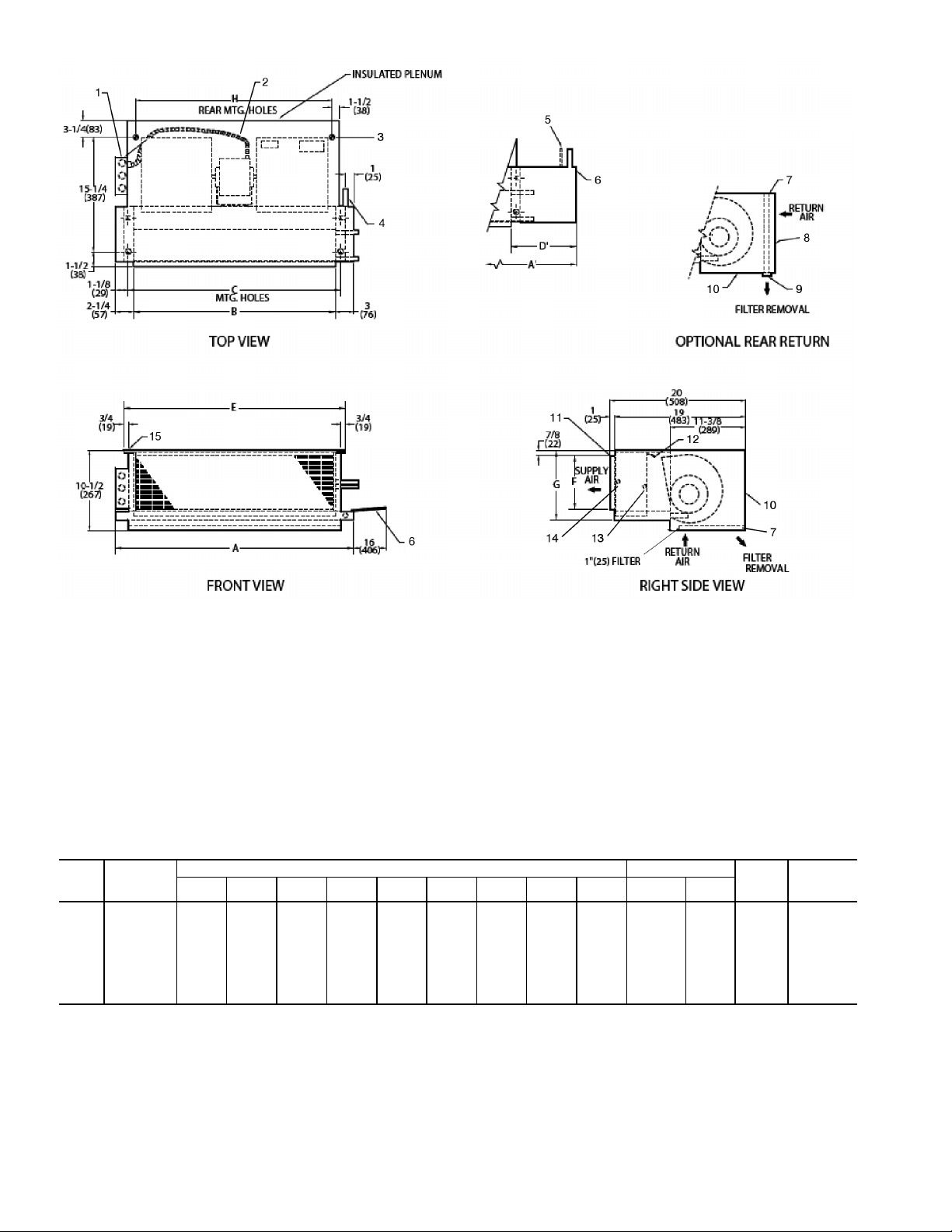
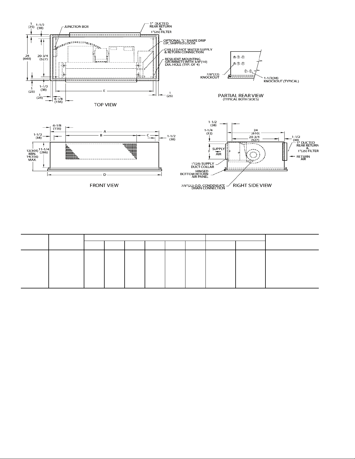
NOTES:
1. Right hand unit with standard 3-row coil shown; left hand unit opposite. Coil
connection locations are ±
5
/
8
-in.
2. Unit sizes 02 and 03 have one motor, one blower; sizes 04 through 08 have
one motor, 2 blowers; sizes 10 and 12 have 2 motors, 4 blowers.
3. Standard 3-row coil shown.
4. Unit available with bottom or rear return air.
5. Dimension increases by 4 in. with optional electric heat.
6. Not shown: 3-speed fan switch; wall plate,
1
/
2
-in. fiberglass insulation on
inside of plenum, closed cell foam on main drain pan.
7. Units have galvanized finish.
8. For optional coil connections, view 42CA-203-1 using the Fan Coil Builder.
9. Dimensions shown in inches (mm).
LEGEND
1— Junction Box, 4 in. x 4 in.
2— Flexible Metal Conduit
3— Mounting Bracket
4— Drain Conn,
7
/
8
-in. OD
5— Tell-Tale Drain Conn,
5
/
8
-in. OD (optional)
6— Drip Lip (optional, shipped loose)
7— Filter
8— Return Duct Collar, 1-in.
9— Filter Access Panel
10 — Access Panel
11 — Supply Duct Collar, 1-in.
12 — Air Vent,
1
/
8
-in. MPT
13 — Return Conn,
5
/
8
-in. OD
14 — Supply Conn,
5
/
8
-in. OD
15 — Hanger Slots (4), Rubber Grommet has
3
/
8
-in. Diameter Hole
*Unit weights are based on dry coils and minimum rows. Weights exclude packaging, valves, and other components.
UNIT
SIZE
NOM
AIRFLOW
(Cfm)
DIMENSIONS (in.) QTY/UNIT FACE
AREA
(sq ft)
UNIT
WEIGHT*
(lb)
AA’B CD’E FGH
Blower Motor
02 200 21
1
/
4
31
1
/
4
16 18
1
/
4
13 19
3
/
4
6
1
/
4
8
3
/
4
15
3
/
8
1 1 0.83 55
03 300 25
1
/
4
36
1
/
4
20 22
1
/
4
14 23
3
/
4
6
1
/
4
8
3
/
4
19
3
/
8
1 1 1.08 60
04 400 31
1
/
4
43
1
/
4
26 28
1
/
4
15 29
3
/
4
6
1
/
4
8
3
/
4
25
3
/
8
2 1 1.35 70
06 600 36
1
/
4
43
1
/
4
31 33
1
/
4
10 34
3
/
4
7
1
/
2
10 30
3
/
8
2 1 1.88 82
08 800 43
1
/
4
57
1
/
4
38 40
1
/
4
17 41
3
/
4
7
1
/
2
10 37
3
/
8
2 1 2.31 95
10 1000 57
1
/
4
65
1
/
4
52 54
1
/
4
11 55
3
/
4
7
1
/
2
10 51
3
/
8
4 2 3.16 135
12 1200 65
1
/
4
75
1
/
4
60 62
1
/
4
13 63
3
/
4
7
1
/
2
10 59
3
/
8
4 2 3.65 154
a42-4101
Fig. 3 — 42CE Furred-In Horizontal Unit with Plenum Dimensions
7
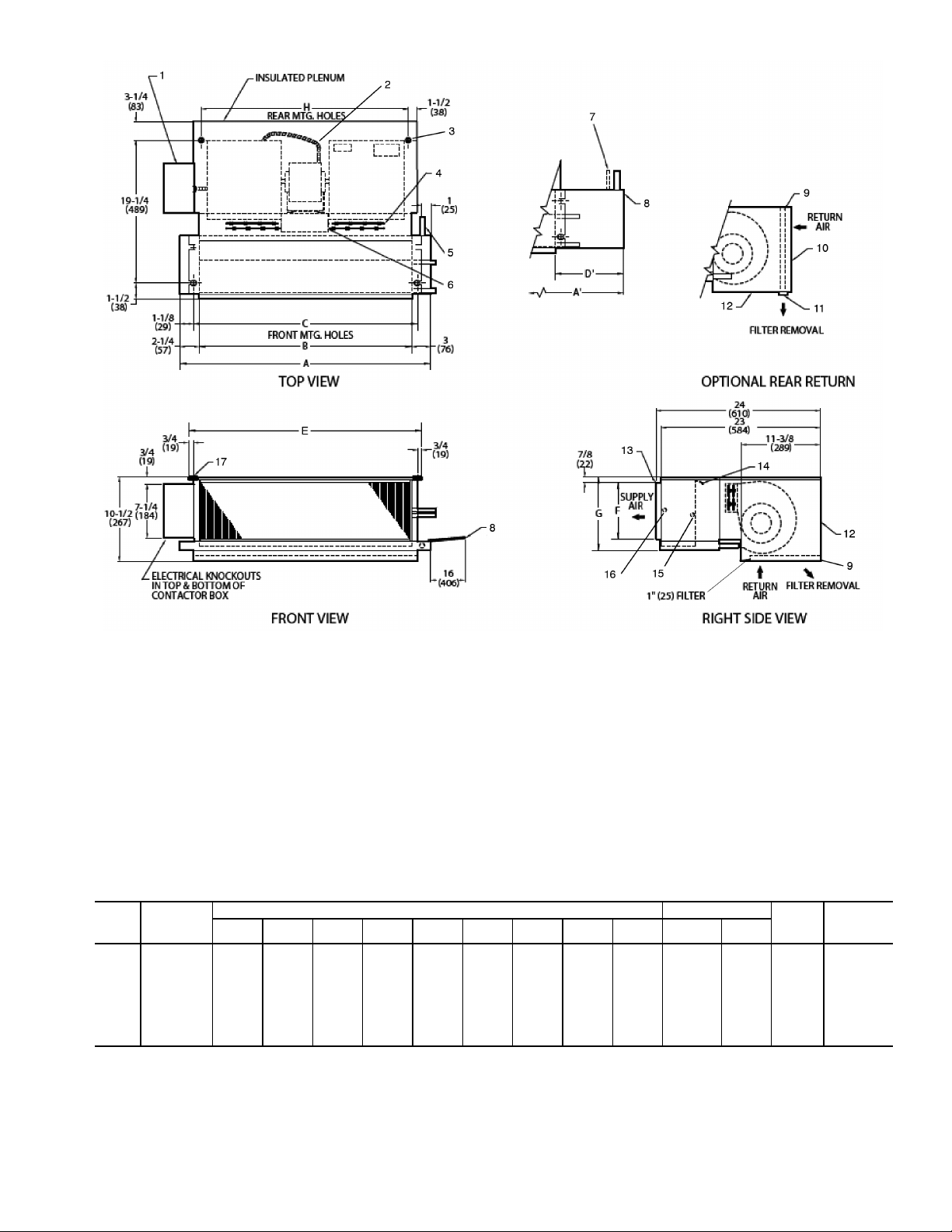
NOTES:
1. Right hand unit with standard 3-row coil shown; left hand unit opposite. Coil
connection locations are ±
5
/
8
-in.
2. Unit sizes 02 and 03 have one motor, one blower; sizes 04 through 08 have
one motor, 2 blowers; sizes 10 and 12 have 2 motors, 4 blowers.
3. Standard 3-row coil shown.
4. Unit available with bottom or rear return air.
5. Dimension increases by 4 in. with optional electric heat.
6. Not shown: 3-speed fan switch; wall plate,
1
/
2
-in. fiberglass insulation on
inside of plenum, closed cell foam on main drain pan.
7. Units have galvanized finish.
8. For optional coil connections, view 42CA-203-1 using the Fan Coil Builder.
9. Dimensions shown in inches (mm).
LEGEND
1— Junction Box, 4 in. x 4 in.
2— Flexible Metal Conduit
3— Mounting Bracket
4— Electric Strip Heater Element
5— Drain Conn,
7
/
8
-in. OD
6— Strip Heater High Limit
7— Tell-Tale Drain Conn,
5
/
8
-in. OD (optional)
8— Drip Lip (optional, shipped loose)
9— Filter
10 — Return Duct Collar, 1-in.
11 — Filter Access Panel
12 — Access Panel
13 — Supply Duct Collar, 1-in.
14 — Air Vent,
1
/
8
-in. MPT
15 — Return Conn,
5
/
8
-in. OD
16 — Supply Conn,
5
/
8
-in. OD
17 — Hanger Slots (4), Rubber Grommet has
3
/
8
-in. Diameter Hole
*Unit weights are based on dry coils and minimum rows. Weights exclude packaging, valves, and other components.
UNIT
SIZE
NOM
AIRFLOW
(Cfm)
DIMENSIONS (in.) QTY/UNIT FACE
AREA
(sq ft)
UNIT
WEIGHT*
(lb)
AA’B CD’E F G H
Blower Motor
02 200 21
1
/
4
31
1
/
4
16 18
1
/
4
13 19
3
/
4
6
1
/
4
8
3
/
4
15
3
/
8
1 1 0.83 57
03 300 25
1
/
4
36
1
/
4
20 22
1
/
4
14 23
3
/
4
6
1
/
4
8
3
/
4
19
3
/
8
1 1 1.08 62
04 400 31
1
/
4
43
1
/
4
26 28
1
/
4
15 29
3
/
4
6
1
/
4
8
3
/
4
25
3
/
8
2 1 1.35 72
06 600 36
1
/
4
43
1
/
4
31 33
1
/
4
10 34
3
/
4
7
1
/
2
10 30
3
/
8
2 1 1.88 84
08 800 43
1
/
4
57
1
/
4
38 40
1
/
4
17 41
3
/
4
7
1
/
2
10 37
3
/
8
2 1 2.31 97
10 1000 57
1
/
4
65
1
/
4
52 54
1
/
4
11 55
3
/
4
7
1
/
2
10 51
3
/
8
4 2 3.16 137
12 1200 65
1
/
4
75
1
/
4
60 62
1
/
4
13 63
3
/
4
7
1
/
2
10 59
3
/
8
4 2 3.65 156
A42-4102
Fig. 4 — 42CE Furred-In Horizontal Unit with Plenum and Electric Heat Dimensions
8
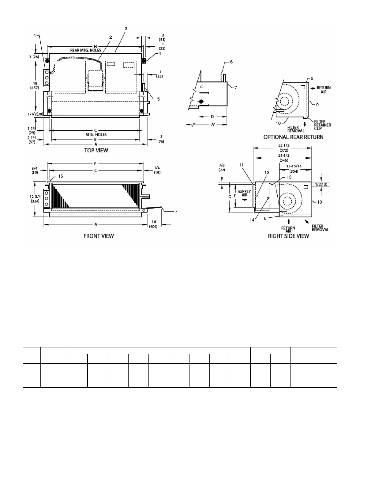
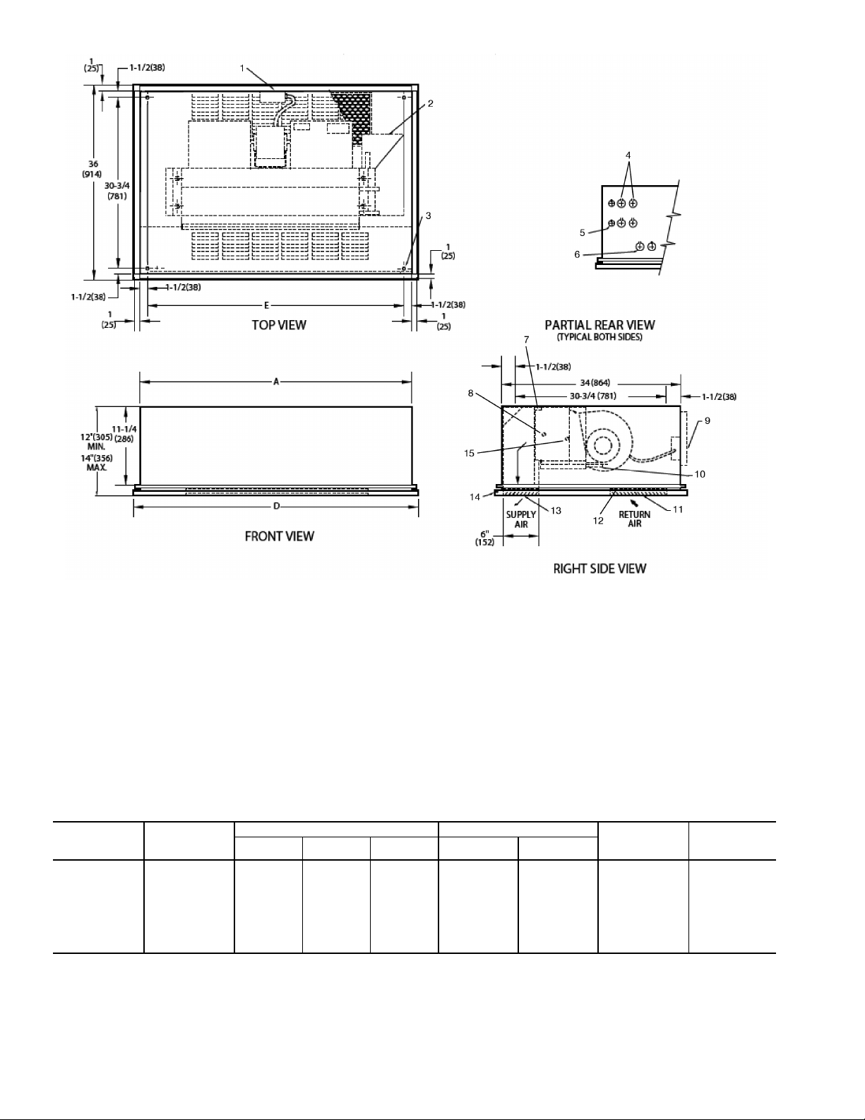
LEGEND
1— Junction Box, Installed with Plenum
2— Flexible Metal Conduit
3— Insulated Plenum
4— Mounting Bracket
5— Drain Conn,
7
/
8
-in. OD
6— Tell-Tale Drain Conn,
5
/
8
-in. OD (optional)
7— Drip Lip (optional, shipped loose)
8— Filter
9— Return Duct Collar, 1-in.
10 — Access Panel
11 — Supply Duct Collar, 1-in.
12 — Supply Conn,
5
/
8
-in. OD
13 — Air Vent,
1
/
8
-in. MPT
14 — Return Conn,
5
/
8
-in. OD
15 — Hanger Slots (4), Rubber Grommet has
3
/
8
-in. Diameter Hole
*Unit weights are based on dry coils and minimum rows. Weights exclude packaging, valves, and other components.
UNIT
SIZE
NOM
AIRFLOW
(Cfm)
DIMENSIONS (in.) QTY/UNIT FACE
AREA
(sq ft)
UNIT
WEIGHT*
(lb)
AA’B CD’E F G H
Blower Motor
04 400 31
1
/
4
43
1
/
4
26 28
1
/
4
15 29
3
/
4
6
1
/
4
8
3
/
4
30
1
/
4
2 1 1.35 84
06 600 36
1
/
4
43
1
/
4
34 33
1
/
4
10 34
3
/
4
7
1
/
2
10 35
1
/
4
2 1 1.88 97
08 800 43
1
/
4
57
1
/
4
38 40
1
/
4
17 41
3
/
4
7
1
/
2
10 42
1
/
4
2 1 2.31 110
10 1000 57
1
/
4
65
1
/
4
52 54
1
/
4
11 55
3
/
4
7
1
/
2
10 56
1
/
4
4 2 3.16 163
NOTES:
1. Right hand unit shown; left hand unit opposite. Coil connection
locations are ±
5
/
8
-in.
2. Unit sizes 04 thru 08 have one motor, 2 blowers; size 10 has
2 motors, 4 blowers.
3. Refer to above figure for configuration of filter and track if
installed in optional plenum.
4. Dimension increases by 4 in. with optional electric heat.
5. Not shown: 3-speed fan switch; wall plate,
1
/
2
-in. fiberglass
insulation on inside of plenum (when installed), closed cell
insulation on main drain pan.
6. Units have galvanized finish.
7. For optional coil connections, view 42CA-203-1 using the Fan
Coil Builder.
8. Dimensions shown in inches (mm).
A42-4103
Fig. 5 — 42CF Furred-In High-Static Horizontal Unit with Plenum Dimensions
9
LEGEND
1— Junction Box, Installed with Plenum
2— Plenum
3— Flexible Metal Conduit
4— Mounting Bracket
5— Electric Strip Heater Element
6— Drain Conn,
7
/
8
-in. OD
7— Drip Lip (optional, shipped loose)
8— Tell-Tale Drain Conn,
5
/
8
-in. OD (optional)
9— Filter
10 — Return Duct Collar, 1-in.
11 — Air Vent,
1
/
8
-in. MPT
12 — Access Panel
13 — Return Conn,
5
/
8
-in. OD
14 — Supply Conn,
5
/
8
-in. OD
15 — Supply Duct Collar, 1-in.
16 — Hanger Slots (4), Rubber Grommet has
3
/
8
-in. Diameter Hole
NOTES:
1. Right hand unit shown; left hand unit opposite. Coil connection
locations are ±
5
/
8
-in.
2. Unit sizes 04 thru 08 have one motor, 2 blowers; size 10 has
2 motors, 4 blowers.
3. Refer to above figure for configuration of filter and track if
installed in optional plenum.
4. Dimension increases by 4 in. with optional electric heat.
5. Not shown: 3-speed fan switch; wall plate,
1
/
2
-in. fiberglass
insulation on inside of plenum (when installed), closed cell
insulation on main drain pan.
6. Units have galvanized finish.
7. For optional coil connections, view 42CA-203-1 using the Fan
Coil Builder.
8. Dimensions shown in inches (mm).
*Unit weights are based on dry coils and minimum rows. Weights exclude packaging, valves, and other components.
UNIT
SIZE
NOM
AIRFLOW
(Cfm)
DIMENSIONS (in.) QTY/UNIT FACE
AREA
(sq ft)
UNIT
WEIGHT*
(lb)
AA’B CD’E F GH
Blower Motor
04 400 31
1
/
4
43
1
/
4
26 28
1
/
4
15 29
3
/
4
6
1
/
4
8
3
/
4
30
1
/
4
2 1 1.35 84
06 600 36
1
/
4
43
1
/
4
34 33
1
/
4
10 34
3
/
4
7
1
/
2
10 35
1
/
4
2 1 1.88 97
08 800 43
1
/
4
57
1
/
4
38 40
1
/
4
17 41
3
/
4
7
1
/
2
10 42
1
/
4
2 1 2.31 110
10 1000 57
1
/
4
65
1
/
4
52 54
1
/
4
11 55
3
/
4
7
1
/
2
10 56
1
/
4
4 2 3.16 163
A42-4104
Fig. 6 — 42CF Furred-In Horizontal Unit with Plenum and Electric Heat Dimensions
10
LEGEND
1— Junction Box, 4 in. x 4 in.
2— Optional Return Air Location
3— Optional Drip Lip, shipped loose
4— Mounting Holes (4), Rubber Grommets
have
3
/
8
-in. Diameter Hole
5— Electrical KO,
7
/
8
-in. Diameter
6— Return KO, 1-in. Diameter
7— Supply KO, 1
1
/
2
-in. Diameter
8— Drain KO, 1
1
/
2
-in. Diameter
9— Supply, Return Connections,
5
/
8
-in. OD
10 — Drain Connection,
7
/
8
-in. OD
11 — Optional Valve Package (inside cabinet)
12 — Filter
13 — Standard Stamped-Return Air Grille
14 — Removable Hinged Access Panel
15 — Supply Grille, Stamped, Standard
*Unit weights are based on dry coils and minimum rows. Weights exclude packaging, valves, and other components.
UNIT
SIZE
NOM
AIRFLOW
(Cfm)
DIMENSIONS (in.) QTY/UNIT FACE
AREA
(sq ft)
UNIT
WEIGHT*
(lb)
ABCEFG
Blower Motor
02 200 38 17
1
/
8
10
7
/
16
34 5
3
/
4
11 1 1 0.83 98
03 300 42 21
1
/
2
10
1
/
4
38 5
3
/
4
11 1 1 1.08 118
04 400 48 25
7
/
8
11
1
/
16
44 5
3
/
4
11 2 1 1.35 126
06 600 53 34
5
/
8
9
3
/
16
49 6
3
/
4
12 2 1 1.88 168
08 800 60 39 10
1
/
2
56 6
3
/
4
12 2 1 2.31 176
10 1000 74 52
1
/
8
10
15
/
16
70 6
3
/
4
12 4 2 3.16 215
12 1200 82 60
7
/
8
10
9
/
16
78 6
3
/
4
12 4 2 3.65 245
NOTES:
1. Right hand unit shown; left hand unit opposite. Coil connection locations
are ±
5
/
8
-in.
2. Unit sizes 02 and 03 have one motor, one blower; sizes 04 through 08
have one motor, 2 blowers; sizes 10 and 12 have 2 motors, 4 blowers.
3. Cabinet has an Arctic White baked finish.
4. Refer to supply and return connections above for coil stub-out locations.
5. Not shown: optional drip lip, 3-speed fan switch; wall plate,
1
/
2
-in. fiber-
glass insulation on inside of casing, closed cell foam on main drain pan.
6. For optional coil connections, view 42CA-203-1 using the Fan Coil
Builder.
7. Valve package is factory-installed inside the cabinet when ordered with
the unit (based on component size).
8. Dimensions shown in inches (mm).
A42-4105
Fig. 7 — 42CG Horizontal Cabinet Unit Dimensions
11
LEGEND
1— Junction Box, 4 in. x 4 in.
2— Optional Stamped Rear Return Grille
3— Optional Drip Lip, shipped loose
4— Electric Strip Heater Element
5— Mounting Holes (4), Rubber Grommets
have
3
/
8
-in. Diameter Hole
6— Electrical KO,
7
/
8
-in. Diameter
7— Return KO, 1-in. Diameter
8— Supply KO, 1
1
/
2
-in. Diameter
9— Drain KO, 1
1
/
2
-in. Diameter
10 — Drain Connection,
7
/
8
-in. OD
11 — Optional Valve Package (inside cabinet)
12 — Filter
13 — Standard Stamped-Return Air Grille
14 — Removable Hinged Access Panel
15 — Supply, Return Connections,
5
/
8
-in. OD
16 — Supply Grille, Stamped, Standard
NOTES:
1. Right hand unit shown; left hand unit opposite. Coil connection
locations are ±
5
/
8
-in.
2. Unit sizes 02 and 03 have one motor, one blower; sizes 04
through 08 have one motor, 2 blowers; sizes 10 and 12 have
2 motors, 4 blowers.
3. Cabinet has an Arctic White baked finish.
4. Refer to supply and return connections above for coil stub-out
locations.
5. Not shown: optional drip lip, 3-speed fan switch; wall plate,
1
/
2
-in. fiberglass insulation on inside of casing, closed cell foam
on main drain pan.
6. For optional coil connections, view 42CA-203-1 using the Fan
Coil Builder.
7. Valve package is factory-installed inside the cabinet when
ordered with the unit (based on component size).
8. Dimensions shown in inches (mm).
*Unit weights are based on dry coils and minimum rows. Weights exclude packaging, valves, and other components.
UNIT
SIZE
NOM
AIRFLOW
(Cfm)
DIMENSIONS (in.) QTY/UNIT FACE
AREA
(sq ft)
UNIT
WEIGHT*
(lb)
ABCE FG
Blower Motor
02 200 38 17
1
/
8
10
7
/
16
34 5
3
/
4
11 1 1 0.83 98
03 300 42 21
1
/
2
10
1
/
4
38 5
3
/
4
11 1 1 1.08 118
04 400 48 25
7
/
8
11
1
/
16
44 5
3
/
4
11 2 1 1.35 126
06 600 53 34
5
/
8
9
3
/
16
49 6
3
/
4
12 2 1 1.88 168
08 800 60 39 10
1
/
2
56 6
3
/
4
12 2 1 2.31 176
10 1000 74 52
1
/
8
10
15
/
16
70 6
3
/
4
12 4 2 3.16 215
12 1200 82 60
7
/
8
10
9
/
16
78 6
3
/
4
12 4 2 3.65 245
A42-4106
Fig. 8 — 42CG Horizontal Cabinet with Electric Heat Dimensions
12
UNIT
SIZE
NOM
AIRFLOW
(Cfm)
DIMENSIONS (in.) QTY/UNIT
BOTTOM RETURN
FILTER SIZE, (in.)
ABCDEFBlowerMotor
02 200 35 16 12
3
/
4
37 32 6 1 1 10 x 28
03 300 35 20 8
3
/
4
37 32 6 1 1 10 x 28
04 400 41 26 8
3
/
4
43 38 6 2 1 10 x 33
06 600 53 31 15
3
/
4
55 50 7 2 1 10 x 45
08 800 53 38 8
3
/
4
55 50 7 2 1 10 x 45
10 1000 75 52 16
3
/
4
77 72 7 4 2 10 x 62
12 1200 75 60 8
3
/
4
77 72 7 4 2 10 x 62
NOTES:
1. Right hand unit shown; left hand unit opposite.
2. Internal factory valve package and drains may not align with
cabinet knockouts.
3. Dimensions shown in inches (mm). All dimensions are ±
1
/
4
in.
4. Bottom panel is Arctic White polyester powder coat paint.
A42-4149
Fig. 9 — 42CK Horizontal Cabinet Unit with Telescopic Access Panel,
Front Supply, and Bottom Return Dimensions
13
NOTES:
1. Right hand unit shown; left hand unit opposite.
2. Internal factory valve package and drains may not align with
cabinet knockouts.
3. Dimensions shown in inches (mm). All dimensions are ±
1
/
4
in.
4. Bottom panel is Arctic White polyester powder coat paint.
UNIT
SIZE
NOM
AIRFLOW
(Cfm)
DIMENSIONS (in.) QTY/UNIT
BOTTOM RETURN
FILTER SIZE, (in.)
A B C D E F Blower Motor
02 200 35 16 12
3
/
4
37 32 6 1 1 10 x 28
03 300 35 20 8
3
/
4
37 32 6 1 1 10 x 28
04 400 41 26 8
3
/
4
43 38 6 2 1 10 x 33
06 600 53 31 15
3
/
4
55 50 7 2 1 10 x 45
08 800 53 38 8
3
/
4
55 50 7 2 1 10 x 45
10 1000 75 52 16
3
/
4
77 72 7 4 2 10 x 62
12 1200 75 60 8
3
/
4
77 72 7 4 2 10 x 62
a42-4150
Fig. 10 — 42CK Horizontal Cabinet Unit with Telescopic Access Panel,
Front Supply, Bottom Return, and Heater Dimensions
14
NOTES:
1. Right hand unit shown; left hand unit opposite.
2. Internal factory valve package and drains may not align with
cabinet knockouts.
3. Dimensions shown in inches (mm). All dimensions are ±
1
/
4
in.
4. Bottom panel is Arctic White polyester powder coat paint.
UNIT
SIZE
NOM
AIRFLOW
(Cfm)
DIMENSIONS (in.) QTY/UNIT
REAR RETURN
FILTER SIZE, (in.)
ABCDEFBlowerMotor
02 200 35 16 12
3
/
4
37 32 6 1 1 7 x 21
03 300 35 20 8
3
/
4
37 32 6 1 1 7 x 21
04 400 41 26 8
3
/
4
43 38 6 2 1 7 x 27
06 600 43 31 15
3
/
4
55 50 7 2 1 7 x 38
08 800 43 38 8
3
/
4
55 50 7 2 1 7 x 38
10 1000 75 52 16
3
/
4
77 72 7 4 2 7 x 52
12 1200 75 60 8
3
/
4
77 72 7 4 2 7 x 52
a42-4151
Fig. 11 — 42CK Horizontal Cabinet Unit with Telescopic Access Panel,
Front Supply, and Rear Return Dimensions
15
NOTES:
1. Right hand unit shown; left hand unit opposite.
2. Internal factory valve package and drains may not align with
cabinet knockouts.
3. Dimensions shown in inches (mm). All dimensions are ±
1
/
4
in.
4. Bottom panel is Arctic White polyester powder coat paint.
UNIT
SIZE
NOM
AIRFLOW
(Cfm)
DIMENSIONS (in.) QTY/UNIT
REAR RETURN
FILTER SIZE, (in.)
ABCDEFBlowerMotor
02 200 35 16 12
3
/
4
37 32 6 1 1 7 x 21
03 300 35 20 8
3
/
4
37 32 6 1 1 7 x 21
04 400 41 26 8
3
/
4
43 38 6 2 1 7 x 27
06 600 43 31 15
3
/
4
55 50 7 2 1 7 x 38
08 800 43 38 8
3
/
4
55 50 7 2 1 7 x 38
10 1000 75 52 16
3
/
4
77 72 7 4 2 7 x 52
12 1200 75 60 8
3
/
4
77 72 7 4 2 7 x 52
a42-4152
Fig. 12 — 42CK Horizontal Cabinet Unit with Telescopic Access Panel,
Front Supply, Rear Return, and Heater Dimensions
16
LEGEND
1— Junction Box, 4 in. x 4 in.
2— Optional Drip Lip, shipped loose
3— Mounting Holes (4), Rubber Grommets
have
3
/
8
-in. Diameter Hole
4— Piping KO, 1
1
/
2
-in. Diameter
5— Electrical KO,
7
/
8
-in. Diameter
6— Drain KO, 1
1
/
2
-in. Diameter
7— Supply Duct Collar
8— Return Connection,
5
/
8
-in. OD.
9— Optional Rear Return. Consult factory for
collar dimensions.
10 — Drain,
7
/
8
-in. OD.
11 — Stamped Bottom Return Air Grille
12 — Filter
13 — Stamped Air Supply Grille
14 — Hinged Bottom Access Panel
15 — Supply Connection,
5
/
8
-in. OD.
*Unit weights are based on dry coils and minimum rows. Weights exclude packaging, valves, and other components.
UNIT
SIZE
NOM
AIRFLOW
(Cfm)
DIMENSIONS (in.) QTY/UNIT
FACE AREA
(sq ft)
UNIT WEIGHT*
(lb)
ADE
Blower Motor
02 200 35 37 32 1 1 0.83 115
03 300 35 37 32 1 1 1.08 120
04 400 41 43 38 2 1 1.35 135
06 600 53 55 50 2 1 1.88 150
08 800 53 55 50 2 1 2.31 155
10 1000 75 77 72 4 2 3.16 227
12 1200 75 77 72 4 2 3.65 241
NOTES:
1. Right hand unit shown; left hand unit opposite. Coil connection
locations are ±
5
/
8
-in.
2. Unit sizes 02 and 03 have one motor, one blower; sizes 04
through 08 have one motor, 2 blowers; sizes 10 and 12 have
2 motors, 4 blowers.
3. Bottom access panel has an Arctic White baked finish.
4. Refer to supply and return connections above for coil stub-out
locations.
5. Not shown: optional drip lip, 3-speed fan switch; wall plate,
1
/
2
-in. fiberglass insulation on inside of casing, closed cell foam
on main drain pan.
6. For optional coil connections, view 42CA-203-1 using the Fan
Coil Builder.
7. Valve package is factory-installed inside the cabinet when
ordered with the unit (based on component size).
8. Bottom return or bottom supply is an ETO (engineering to order)
request.
9. Dimensions shown in inches (mm).
A42-4107
Fig. 13 — 42CK Horizontal Cabinet Unit with Telescopic Access Panel
17
LEGEND
1— Junction Box, 4 in. x 4 in.
2— Strip Heater High Limit
3— Electric Strip Heater Element
4— Optional Drip Lip, shipped loose
5— Mounting Holes (4), Rubber Grommets
have
3
/
8
-in. Diameter Hole
6— Piping KO, 1
1
/
2
-in. Diameter
7— Electrical KO,
7
/
8
-in. Diameter
8— Drain KO, 1
1
/
2
-in. Diameter
9— Supply Duct Collar
10 — Optional Rear Return. Consult factory for
collar dimensions.
11 — Drain,
7
/
8
-in. OD.
12 — Stamped Bottom Return Air Grille
13 — Filter
14 — Stamped Air Supply Grille
15 — Hinged Bottom Access Panel
16 — Supply Connection,
5
/
8
-in. OD.
17 — Return Connection,
5
/
8
-in. OD.
NOTES:
1. Right hand unit shown; left hand unit opposite. Coil connection
locations are ±
5
/
8
-in.
2. Unit sizes 02 and 03 have one motor, one blower; sizes 04
through 08 have one motor, 2 blowers; sizes 10 and 12 have
2 motors, 4 blowers.
3. Bottom access panel has an Arctic White baked finish.
4. Refer to supply and return connections above for coil stub-out
locations.
5. Not shown: optional drip lip, 3-speed fan switch; wall plate,
1
/
2
-in. fiberglass insulation on inside of casing, closed cell foam
on main drain pan.
6. For optional coil connections, view 42CA-203-1 using the Fan
Coil Builder.
7. Valve package is factory-installed inside the cabinet when
ordered with the unit (based on component size).
8. Bottom return or bottom supply is an ETO (engineering to order)
request.
9. Dimensions shown in inches (mm).
*Unit weights are based on dry coils and minimum rows. Weights exclude packaging, valves, and other components.
UNIT SIZE
NOM AIRFLOW
(Cfm)
DIMENSIONS (in.) QTY/UNIT
FACE AREA
(sq ft)
UNIT WEIGHT*
(lb)
ADEBlowerMotor
02 200 35 37 32 1 1 0.83 117
03 300 35 37 32 1 1 1.08 122
04 400 41 43 38 2 1 1.35 137
06 600 53 55 50 2 1 1.88 152
08 800 53 55 50 2 1 2.31 157
10 1000 75 77 72 4 2 3.16 229
12 1200 75 77 72 4 2 3.65 243
A42-4108
Fig. 14 — 42CK Horizontal Cabinet with Telescopic Access Panel and Electric Heat Dimensions
18
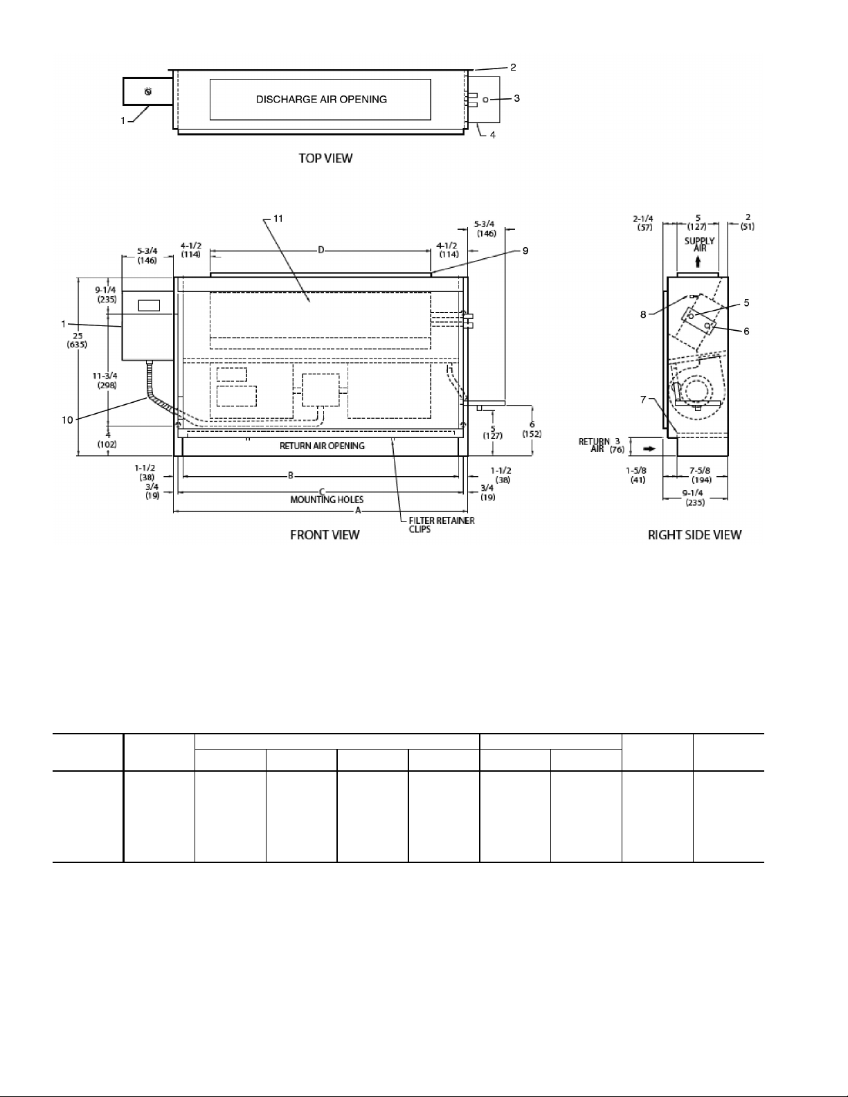
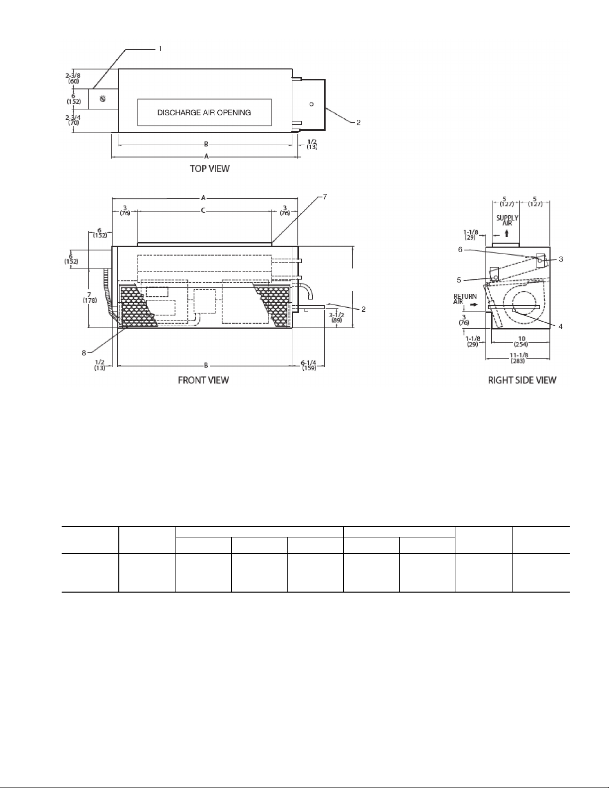
LEGEND
1— Optional Unit Mounted Control Box
2— Wall Mounting Holes (4),
3
/
4
-in. Diameter
3— Drain,
3
/
4
-in. MPT
4— Drain Pan, Auxiliary, Shipped Loose
5— Supply Conn,
5
/
8
-in. OD
6— Return Conn,
5
/
8
-in. OD
7— Filter
8— Air Vent,
1
/
8
-in. MPT
9— Discharge Opening
10 — Flexible Conduit
11 — Front Access Panel
*Unit weights are based on dry coils and minimum rows. Weights exclude packaging, valves, and other components.
UNIT
SIZE
NOM
AIRFLOW
(Cfm)
DIMENSIONS (in.) QTY/UNIT FACE
AREA
(sq ft)
UNIT
WEIGHT*
(lb)
ABCD
Blower Motor
02 200 25 22 23
1
/
2
16 1 1 0.83 65
03 300 29 26 27
1
/
2
20 1 1 1.08 80
04 400 35 32 33
1
/
2
26 2 1 1.35 90
06 600 45 42 43
1
/
2
36 2 1 1.88 112
08 800 47 44 45
1
/
2
38 2 1 2.31 115
10 1000 61 58 59
1
/
2
52 4 2 3.16 140
12 1200 69 66 67
1
/
2
60 4 2 3.65 170
NOTES:
1. Right hand unit shown; left hand unit opposite. Coil connection locations
are ±
5
/
8
-in.
2. Unit sizes 02 and 03 have one motor, one blower; sizes 04 through 08
have one motor, 2 blowers; sizes 10 and 12 have 2 motors, 4 blowers.
3. Standard 3-row coil shown.
4. Optional unit-mounted switch box and controls, when specified, are
installed on opposite side from cooling connections.
5. Not shown: 3-speed fan switch; wall plate,
1
/
2
-in. fiberglass insulation on
inside of casing, closed cell foam on main drain pan.
6. Units have galvanized finish.
7. For optional coil connections, view 42VA-203-1 using the Fan Coil
Builder.
8. Dimensions shown in inches (mm).
A42-4109
Fig. 15 — 42VA Furred-In Vertical Unit Dimensions
19
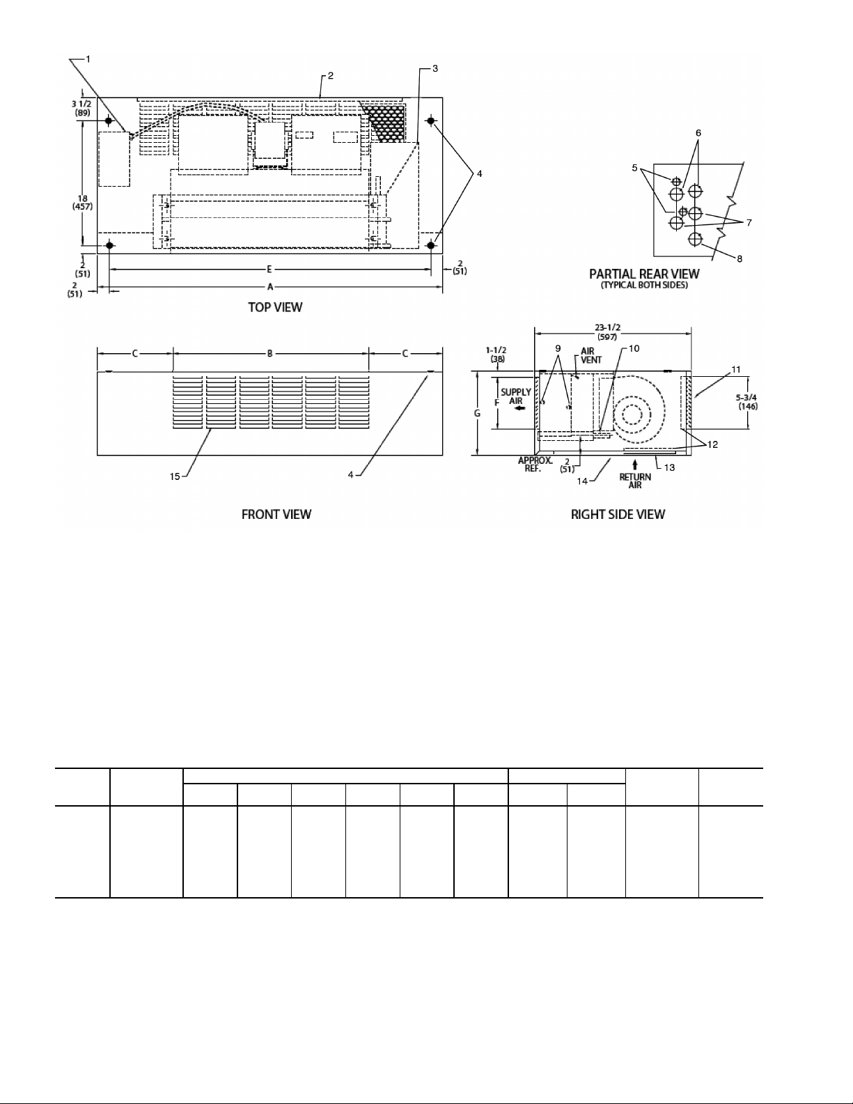
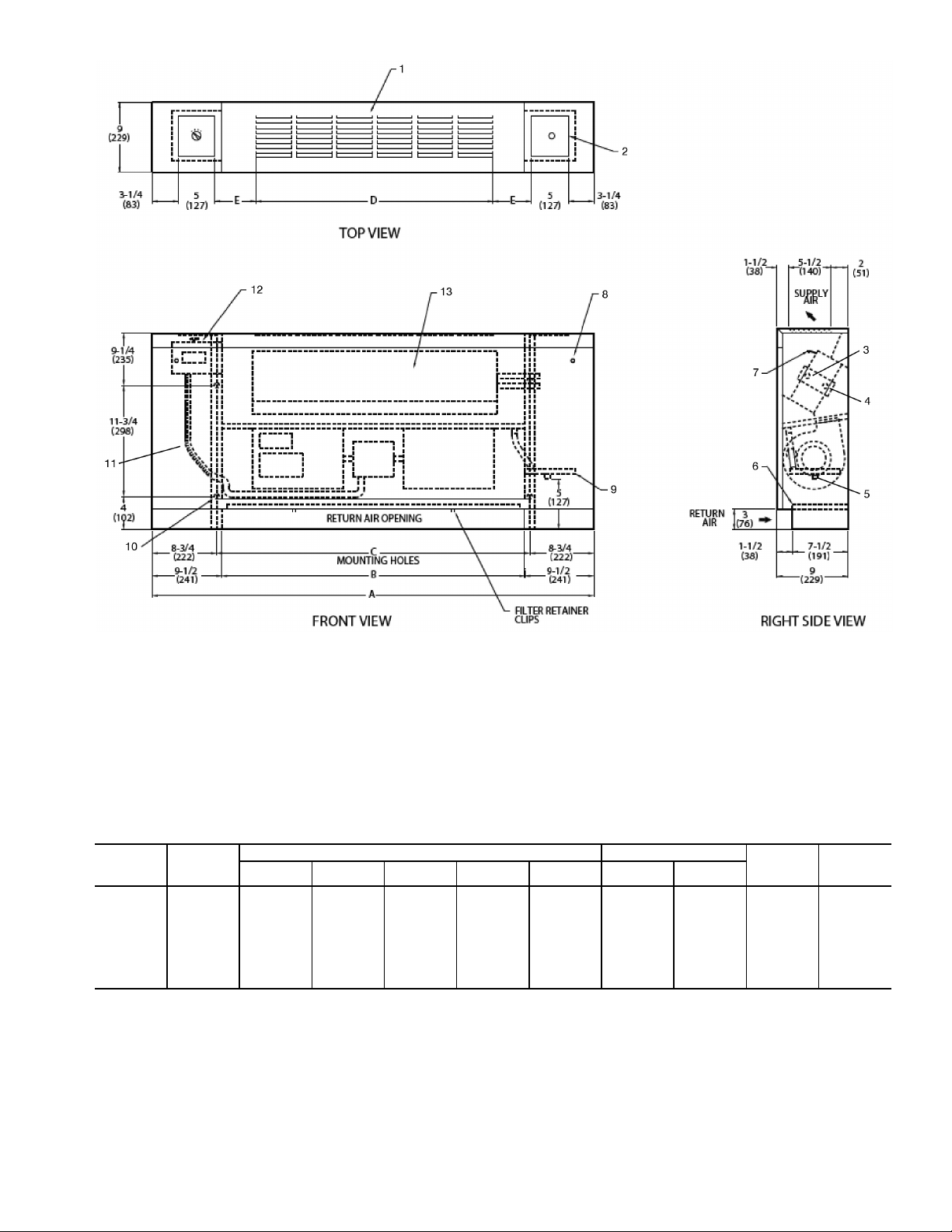
LEGEND
1— Standard Stamped Supply Grille
2— Access Door, Fan Switch
3— Supply Conn,
5
/
8
-in. OD
4— Return Conn,
5
/
8
-in. OD
5— Drain,
3
/
4
-in. MPT
6— Filter
7— Air Vent,
1
/
8
-in. MPT
8— Front Panel Fastener
9— Drain Pan, Auxiliary, Shipped Loose
10 — Wall Mounting Holes (4),
3
/
4
-in. Diameter
11 — Flexible Conduit
12 — Fan Switch, 3-speed
13 — Front Access Panel
NOTES:
1. Right hand unit shown; left hand unit opposite. Coil connection
locations are ±
5
/
8
-in.
2. Unit sizes 02 and 03 have one motor, one blower; sizes 04 through
08 have one motor, 2 blowers; sizes 10 and 12 have 2 motors,
4 blowers.
3. Standard 3-row coil shown.
4. Cabinet has an Arctic White baked finish.
5. Stamped supply grille standard. Optional single or double deflec-
tion grilles available.
6. Not shown:
1
/
2
-in. fiberglass insulation on inside of casing, closed
cell foam on main drain pan.
7. For optional coil connections, view 42VA-203-1 using the Fan Coil
Builder.
8. Dimensions shown in inches (mm).
*Unit weights are based on dry coils and minimum rows. Weights exclude packaging, valves, and other components.
UNIT
SIZE
NOM
AIRFLOW
(Cfm)
DIMENSIONS (in.) QTY/UNIT FACE
AREA
(sq ft)
UNIT
WEIGHT*
(lb)
ABCDE
Blower Motor
02 20041 2223
1
/
2
17
1
/
4
3
5
/
8
1 1 0.83 89
03 30045 2627
1
/
2
21
1
/
2
3
1
/
2
1 1 1.08 95
04 40051 3233
1
/
2
26 4
1
/
4
2 1 1.35 116
06 60061 4243
1
/
2
39 2
3
/
4
2 1 1.88 134
08 80063 4445
1
/
2
39 3
3
/
4
2 1 2.31 137
10 100077 5859
1
/
2
52 4
1
/
4
4 2 3.16 169
12 120085 6667
1
/
2
61 3
3
/
4
4 2 3.65 192
A42-4110
Fig. 16 — 42VB Vertical Cabinet Unit Dimensions
20
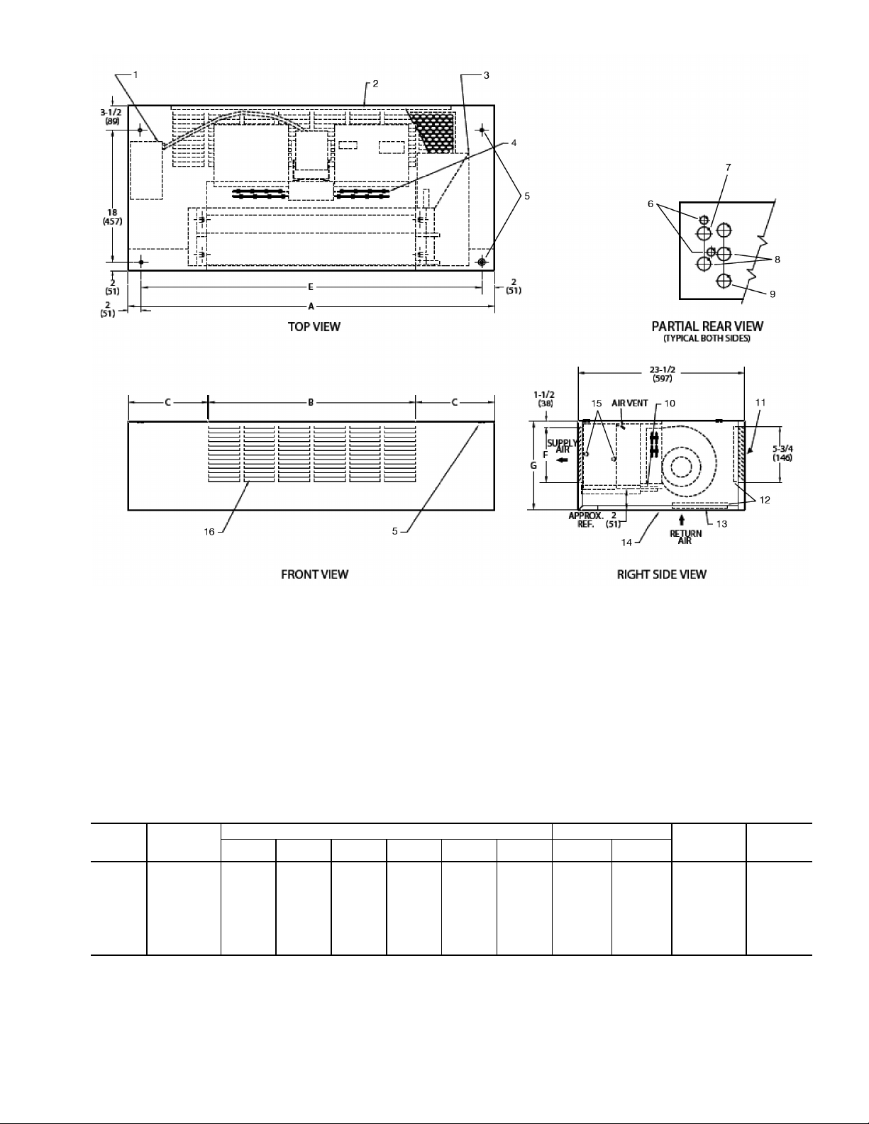
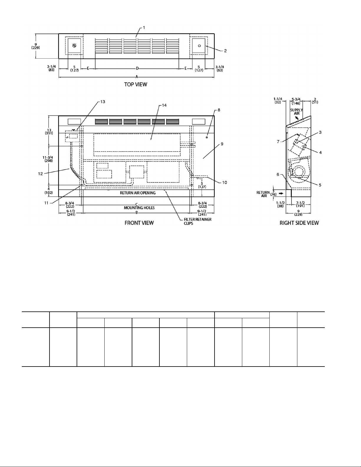
LEGEND
1— Standard Stamped Supply Grille
2— Access Door, Fan Switch
3— Supply Conn,
5
/
8
-in. OD
4— Return Conn,
5
/
8
-in. OD
5— Drain,
3
/
4
-in. MPT
6— Filter
7— Air Vent,
1
/
8
-in. MPT
8— Front Panel Fastener
9— Optional Valve Package (inside cabinet)
10 — Drain Pan, Auxiliary, Shipped Loose
11 — Wall Mounting Holes
3
/
4
-in. Diameter
12 — Flexible Conduit
13 — Fan Switch, 3 speed
14 — Access Doors
NOTES:
1. Right hand unit shown; left hand unit opposite. Coil connection
locations are ±
5
/
8
-in.
2. Unit sizes 02 and 03 have one motor, one blower; sizes 04
through 08 have one motor, 2 blowers; sizes 10 and 12 have
2 motors, 4 blowers.
3. Standard 3-row coil shown.
4. Cabinet has an Arctic White baked finish.
5. Not shown:
1
/
2
-in. fiberglass insulation on inside of casing,
closed cell foam on main drain pan.
6. For optional coil connections, view 42VA-203-1 using the Fan
Coil Builder.
7. Valve package is factory-installed inside the cabinet when
ordered with the unit (based on component size).
8. Dimensions shown in inches (mm).
*Unit weights are based on dry coils and minimum rows. Weights exclude packaging, valves, and other components.
UNIT
SIZE
NOM
AIRFLOW
(Cfm)
DIMENSIONS (in.) QTY/UNIT FACE
AREA
(sq ft)
UNIT
WEIGHT*
(lb)
ABCDE
Blower Motor
02 200 41 22 23
1
/
2
17
1
/
4
3
5
/
8
1 1 0.83 92
03 300 45 26 27
1
/
2
21
1
/
2
3
1
/
2
1 1 1.08 98
04 400 51 32 33
1
/
2
26 4
1
/
4
2 1 1.35 122
06 600 61 42 43
1
/
2
39 2
3
/
4
2 1 1.88 141
08 800 63 44 45
1
/
2
39 3
3
/
4
2 1 2.31 144
10 1000 77 58 59
1
/
2
52
1
/
8
4
1
/
4
4 2 3.16 178
12 1200 85 66 67
1
/
2
61 3
3
/
4
4 2 3.65 205
A42-4111
Fig. 17 — 42VF Vertical Cabinet Unit with Slant Top Dimensions
21
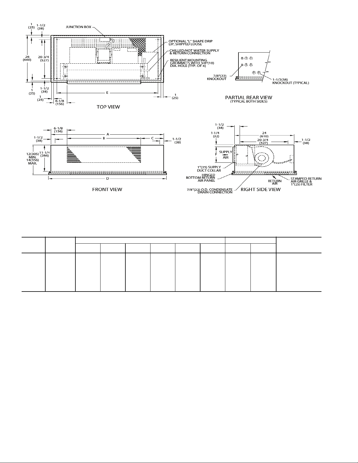
LEGEND
1— Optional Unit Mounted Control Box
2— Drain Pan, Auxiliary, Shipped Loose
3— Supply Conn,
5
/
8
-in. OD
4— Drain,
3
/
4
-in. MPT
5— Return Conn,
5
/
8
-in. OD
6— Air Vent,
1
/
8
-in. MPT
7— Discharge Opening
8— Filter
*Unit weights are based on dry coils and minimum rows. Weights exclude packaging, valves, and other components.
UNIT SIZE
NOM
AIRFLOW
(Cfm)
DIMENSIONS (in.) QTY/UNIT
FACE AREA
(sq ft)
UNIT
WEIGHT* (lb)
ABC
Blower Motor
02 200 23 22 17 2 1 1.18 50
03 300 28 27 22 2 1 1.53 60
04 400 36 35 30 2 1 2.08 72
06 600 50 49 44 4 2 3.06 110
NOTES:
1. Right hand unit shown; left hand unit opposite. Coil connection
locations are ±
5
/
8
-in.
2. Unit sizes 02 through 04 have one motor, 2 blowers; size 06
has 2 motors, 4 blowers.
3. Standard 2-row coil shown.
4. Optional unit-mounted switch box and controls, when specified,
are installed on opposite side from cooling connections.
5. Height increases by 2 in. with electric heat.
6. Not shown: 3-speed fan switch,
1
/
2
-in. fiberglass insulation on
inside of casing, closed cell foam on main drain pan.
7. Units have galvanized finish.
8. For optional coil connections, view 42VC-203-1 using the Fan
Coil Builder.
9. Dimensions shown in inches (mm).
A42-4112
14-3/8
(368)
Fig. 18 — 42VC Furred-In Lowboy Unit Dimensions
22
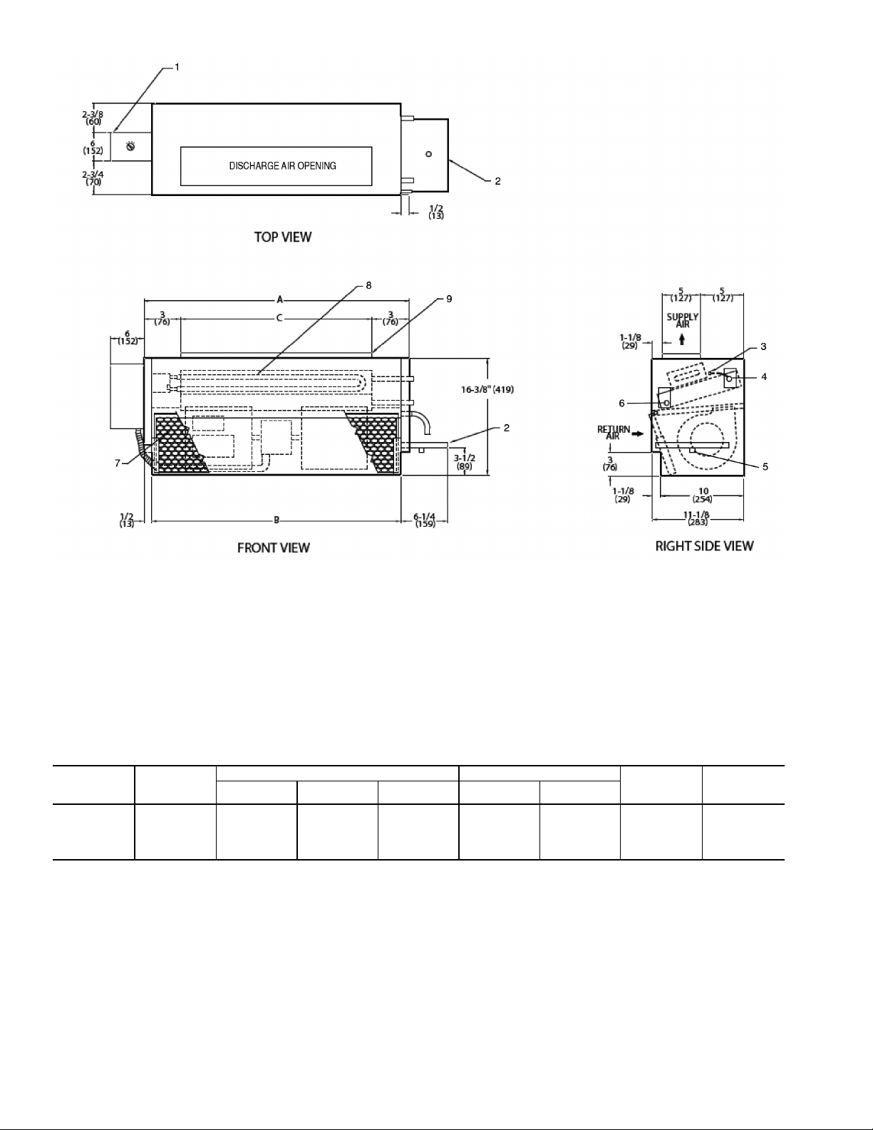
LEGEND
1— Unit-Mounted Control Box (Optional)
2— Drain Pan, Auxiliary, Shipped Loose
3— Air Vent,
1
/
8
-in. MPT
4— Supply Conn,
5
/
8
-in. OD
5— Drain,
3
/
4
-in. MPT
6— Return Conn,
5
/
8
-in. OD
7— Filter
8— Electrical Sheath Heater Element
9— Discharge Opening
*Unit weights are based on dry coils and minimum rows. Weights exclude packaging, valves, and other components.
UNIT SIZE
NOM
AIRFLOW
(Cfm)
DIMENSIONS (in.) QTY/UNIT
FACE AREA
(sq ft)
UNIT
WEIGHT* (lb)
ABC
Blower Motor
02 200 23 22 17 2 1 1.18 50
03 300 28 27 22 2 1 1.53 60
04 400 36 35 30 2 1 2.08 72
06 600 50 49 44 4 2 3.06 110
NOTES:
1. Right hand unit shown; left hand unit opposite. Coil connection
locations are ±
5
/
8
-in.
2. Unit sizes 02 through 04 have one motor, 2 blowers; size 06 has
2 motors, 4 blowers.
3. Standard 2-row coil shown.
4. Optional unit-mounted switch box and controls, when specified,
are installed on opposite side from cooling connections.
5. Height increases by 2 in. with electric heat.
6. Not shown: 3-speed fan switch,
1
/
2
-in. fiberglass insulation on
inside of casing, closed cell foam on main drain pan.
7. Units have galvanized finish.
8. For optional coil connections, view 42VC-203-1 using the Fan Coil
Builder.
9. Dimensions shown in inches (mm).
A42-4113
Fig. 19 — 42VC Furred-In Lowboy Unit with Electric Heat Dimensions
 Loading...