


40RM
40RMQ
40RMS Packaged Air-Handling Units 50/60 Hz
Installation, Start-Up and
Service Instructions
CONTENTS
Page
SAFETY CONSIDERATIONS . . . . . . . . . . . . . . . . . 1
PRE-INSTALLATION . . . . . . . . . . . . . . . . . . . . . . . . 1
Moving and Storage . . . . . . . . . . . . . . . . . . . . . . . . 1
Rigging . . . . . . . . . . . . . . . . . . . . . . . . . . . . . . . . . . . . 1
INSTALLATION . . . . . . . . . . . . . . . . . . . . . . . . . . . 1-23
General . . . . . . . . . . . . . . . . . . . . . . . . . . . . . . . . . . . . 1
Uncrating . . . . . . . . . . . . . . . . . . . . . . . . . . . . . . . . . . 1
Accessories . . . . . . . . . . . . . . . . . . . . . . . . . . . . . . . . 1
Unit Positioning . . . . . . . . . . . . . . . . . . . . . . . . . . . . 11
Unit Isolation . . . . . . . . . . . . . . . . . . . . . . . . . . . . . . 12
Refrigerant and Chilled Water
Piping Access . . . . . . . . . . . . . . . . . . . . . . . . . . . . . 12
Refrigerant Piping . . . . . . . . . . . . . . . . . . . . . . . . . . 12
Chilled Water Piping . . . . . . . . . . . . . . . . . . . . . . . 17
Condensate Drain . . . . . . . . . . . . . . . . . . . . . . . . . . 18
Fan Motors and Drives . . . . . . . . . . . . . . . . . . . . . 18
Power Supply and Wiring . . . . . . . . . . . . . . . . . . . 19
Connecting Ductwork . . . . . . . . . . . . . . . . . . . . . . 22
Return-Air Filters . . . . . . . . . . . . . . . . . . . . . . . . . . 22
START-UP . . . . . . . . . . . . . . . . . . . . . . . . . . . . . . . . . |
23 |
SERVICE . . . . . . . . . . . . . . . . . . . . . . . . . . . . . . . . . 23-39
Panels . . . . . . . . . . . . . . . . . . . . . . . . . . . . . . . . . . . . . 23
Fan Motor Lubrication . . . . . . . . . . . . . . . . . . . . . . 23
Fan Shaft Bearings . . . . . . . . . . . . . . . . . . . . . . . . . 23
Centering Fan Wheel . . . . . . . . . . . . . . . . . . . . . . . 24
Fan Shaft Position Adjustment . . . . . . . . . . . . . . 24
Individual Fan Wheel Adjustment . . . . . . . . . . . 24
Fan Belts . . . . . . . . . . . . . . . . . . . . . . . . . . . . . . . . . . 24
Fan Rotation . . . . . . . . . . . . . . . . . . . . . . . . . . . . . . . 24
Fan Pulley Alignment . . . . . . . . . . . . . . . . . . . . . . . 25
Pulley and Drive Adjustment . . . . . . . . . . . . . . . . 25
Condensate Drains . . . . . . . . . . . . . . . . . . . . . . . . . 25
Return-Air Filters . . . . . . . . . . . . . . . . . . . . . . . . . . 25
Chilled Water Coil Freeze Protection . . . . . . . . 25
Coil Removal . . . . . . . . . . . . . . . . . . . . . . . . . . . . . . 25
Cleaning Cooling Coil . . . . . . . . . . . . . . . . . . . . . . 25
Cleaning Insulation . . . . . . . . . . . . . . . . . . . . . . . . 25
Replacing Filters . . . . . . . . . . . . . . . . . . . . . . . . . . . 39
START-UP CHECKLIST . . . . . . . . . . . . . . . . CL-1,CL-2
SAFETY CONSIDERATIONS
Installing, starting up, and servicing this equipment can be hazardous due to system pressures, electrical components and equipment location (elevated structures, etc.).
Only trained, quali®ed installers and service mechanics should install, start up, and service this equipment.
Untrained personnel can perform basic maintenance functions such as cleaning coils, and cleaning and replacing
®lters. All other operations should be performed by trained service personnel.
When working on the equipment, observe precautions in the literature and on tags, stickers, and labels attached to the equipment.
·Follow all safety codes.
·Wear safety glasses and work gloves.
·Use care in handling, rigging, and setting bulky equipment.
Be sure all power to equipment is shut off before performing maintenance or service. More than one disconnect may be present.
PRE-INSTALLATION
Moving and Storage Ð To transfer unit from truck to storage site, use a fork truck. Do not stack units more than 2 high during storage. If unit is to be stored for more than 2 weeks before installation, choose a level, dry storage site free from vibration. Do not remove plastic wrap or skid from unit until ®nal installation.
Rigging Ð All 40RM Series units can be rigged by using the shipping skid. Units are shipped fully assembled. Do not remove shipping skids or protective covering until unit is ready for ®nal placement; damage to bottom panels can result. Use slings and spreader bars as applicable to lift unit.
INSTALLATION
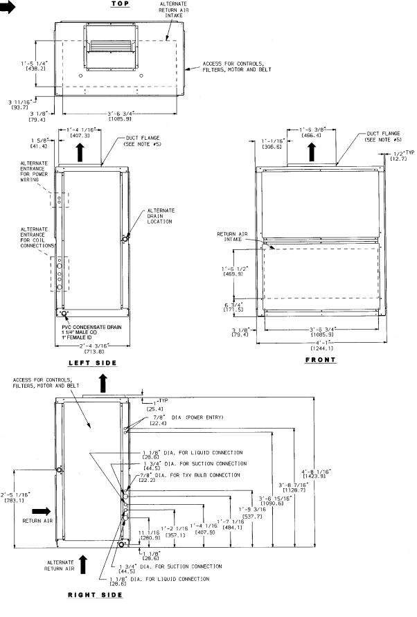
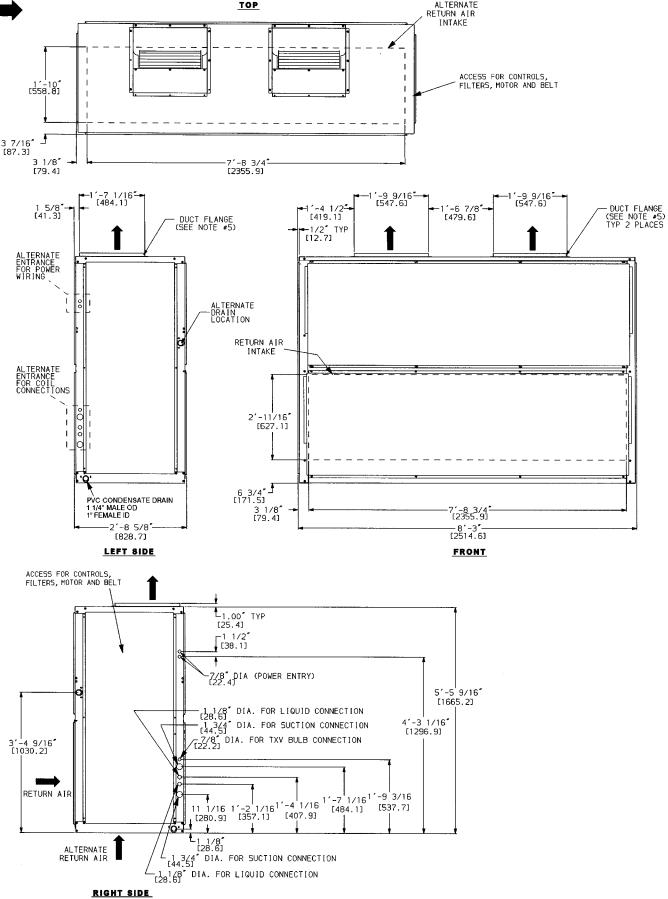
General Ð Allow 21¤2 ft at front and side of unit for service clearance and air¯ow. For units equipped with an economizer, refer to the accessory installation instructions for additional clearance requirements. Be sure ¯oor, wall, or ceiling can support unit weight (Tables 1A-1F). See Fig. 1A-1C for dimensions.
Uncrating Ð Move unit as near as possible to ®nal location before removing shipping skid.
Remove metal banding, top skid, and plastic wrap. Examine unit for shipping damage. If shipping damage is evident, ®le claim with transportation agency. Remove base skid just prior to actual installation.
Check nameplate information against available power supply and model number description in Fig. 2.
Accessories Ð Refer to instructions shipped with each accessory for speci®c information.
Manufacturer reserves the right to discontinue, or change at any time, speci®cations or designs without notice and without incurring obligations.
Book |
1 |
4 |
|
PC 111 |
Catalog No. 534-053 |
Printed in U.S.A. |
Form 40RM-9SI |
Pg 1 |
11-95 |
Replaces: 40RM-1SI |
Tab |
3c |
2e |
|
|
|
|
|
|
|
|
|
|
|
|
|
|
|
|
|
|
|
Table 1A Ð 40RM Physical Data, English
UNIT 40RM |
007 |
|
008 |
|
012 |
014 |
|
016 |
|
024 |
028 |
|
034 |
NOMINAL CAPACITY (Tons) |
6 |
|
71¤2 |
|
10 |
121¤2 |
|
15 |
|
20 |
25 |
|
30 |
OPERATING WEIGHT (lb) |
|
|
|
|
|
|
|
|
|
|
|
|
|
Base Unit with TXV |
381 |
|
385 |
|
405 |
670 |
|
685 |
|
690 |
1020 |
|
1030 |
Plenum |
97 |
|
97 |
|
97 |
140 |
|
140 |
|
140 |
180 |
|
180 |
FANS |
|
|
|
|
|
|
|
|
|
|
|
|
|
Qty...Diam. (in.) |
1...15 |
|
1...15 |
|
1...15 |
2...15 |
|
2...15 |
|
2...15 |
2...18 |
|
2...18 |
Nominal Air¯ow (cfm) |
2400 |
|
3000 |
|
4000 |
5000 |
|
6000 |
|
8,000 |
10,000 |
|
12,000 |
Air¯ow Range (cfm) |
1800- |
|
2250- |
|
3000- |
3750- |
|
4500- |
|
6,000- |
7,500- |
|
9,000- |
3000 |
|
3750 |
|
5000 |
6250 |
|
7500 |
|
10,000 |
12,500 |
|
15,000 |
|
Nominal Motor Hp (Standard Motor) |
|
|
|
|
|
||||||||
|
|
|
|
|
|
|
|
|
|
|
|
|
|
208/230-1-60 |
1.3 |
|
2.4 |
|
Ð |
Ð |
|
Ð |
|
Ð |
Ð |
|
Ð |
208/230-3-60 and 460-3-60 |
2.4 |
|
2.4 |
|
2.4 |
2.9 |
|
3.7 |
|
5.0 |
7.5 |
|
10.0 |
575-3-60 |
1.0 |
|
2.0 |
|
2.0 |
3.0 |
|
3.0 |
|
5.0 |
7.5 |
|
10.0 |
230-3-50, 400-3-50 |
2.4 |
|
2.4 |
|
2.9 |
2.9 |
|
2.9 |
|
5.0 |
7.5 |
|
10.0 |
Motor Speed (rpm) |
|
|
|
|
|
|
|
|
|
|
|
|
|
208/230-1-60 |
1725 |
|
1725 |
|
Ð |
Ð |
|
Ð |
|
Ð |
Ð |
|
Ð |
208/230-3-60 and 460-3-60 |
1725 |
|
1725 |
|
1725 |
1725 |
|
1725 |
|
1745 |
1745 |
|
1745 |
575-3-60 |
1725 |
|
1725 |
|
1725 |
1725 |
|
1725 |
|
1745 |
1755 |
|
1755 |
230-3-50, 400-3-50 |
1425 |
|
1425 |
|
1425 |
1425 |
|
1425 |
|
1425 |
1425 |
|
1425 |
REFRIGERANT |
|
|
|
|
|
|
R-22 |
|
|
|
|
||
Operating charge (lb) |
3.0 |
|
3.0 |
|
1.5/1.5 |
2.0/2.0 |
|
2.5/2.5 |
|
3.5/3.5 |
4.5/4.5 |
|
5.0/5.0 |
(approx per circuit)* |
|
|
|
|
|
||||||||
|
|
|
|
|
|
|
|
|
|
|
|
|
|
DIRECT-EXPANSION COIL |
|
|
|
Enhanced Copper Tubes, Aluminum Sine-Wave Fins |
|
|
|||||||
Max Working Pressure (psig) |
|
|
|
|
|
|
435 |
|
|
|
|
|
|
Face Area (sq ft) |
6.67 |
|
8.33 |
|
10.0 |
13.25 |
|
17.67 |
|
19.88 |
24.86 |
|
29.83 |
No. of Splits |
1 |
|
1 |
|
2 |
2 |
|
2 |
|
2 |
2 |
|
2 |
No. of Circuits per Split |
12 |
|
15 |
|
9 |
9 |
|
12 |
|
13 |
15 |
|
18 |
Split Type...Percentage |
Ð |
|
Ð |
|
|
|
|
Face... |
50/50 |
|
|
|
|
Rows...Fins/in. |
3...15 |
|
3...15 |
|
3...17 |
3...15 |
|
3...15 |
|
3...17 |
3...15 |
|
3...15 |
STEAM COIL |
|
|
|
|
|
|
|
|
|
|
|
|
|
Max Working Pressure (psig at 400 F) |
|
|
|
|
|
|
175 |
|
|
|
|
|
|
Total Face Area (sq ft) |
6.67 |
|
6.67 |
|
6.67 |
13.33 |
|
13.33 |
|
13.33 |
15.0 |
|
15.0 |
Rows...Fins/in. |
1...9 |
|
1...9 |
|
1...9 |
1...10 |
|
1...10 |
|
1...10 |
1...10 |
|
1...10 |
HOT WATER COIL |
|
|
|
|
|
|
|
|
|
|
|
|
|
Max Working Pressure (psig) |
|
|
|
|
|
|
150 |
|
|
|
|
|
|
Total Face Area (sq ft) |
6.67 |
|
6.67 |
|
6.67 |
13.33 |
|
13.33 |
|
13.33 |
15.0 |
|
15.0 |
Rows...Fins/in. |
2...8.5 |
|
2...8.5 |
|
2...8.5 |
2...8.5 |
|
2...8.5 |
|
2...8.5 |
2...12.5 |
|
2...12.5 |
Water Volume |
|
|
|
|
|
|
|
|
|
|
|
|
|
(gal) |
|
|
8.3 |
|
|
|
|
13.9 |
|
|
14.3 |
||
(ft3) |
|
1.1 |
|
|
|
1.85 |
|
|
|
1.90 |
|||
PIPING CONNECTIONS, |
|
|
|
|
|
|
|
|
|
|
|
|
|
Quantity...Size (in.) |
|
|
|
|
|
|
|
|
|
|
|
|
|
DX Coil Ð Suction (ODF) |
1...11¤8 |
|
1...11¤8 |
|
2...11¤8 |
2...11¤8 |
|
2...11¤8 |
|
2...11¤8 |
2...13¤8 |
|
2...13¤8 |
DX Coil Ð Liquid Refrigerant (ODF) |
1... |
5¤8 |
|
|
|
|
2...5¤8 |
|
|
|
|||
Steam Coil, In (MPT) |
1...21¤2 |
|
|
|
1...21¤2 |
|
|
|
|||||
Steam Coil, Out (MPT) |
1...11¤2 |
|
|
|
1...11¤2 |
|
|
|
|||||
Hot Water Coil, In (MPT) |
1...11¤2 |
|
1...11¤2 |
|
|
|
|
1...2 |
|
|
|
||
Hot Water Coil, Out (MPT) |
1...11¤2 |
|
1...11¤2 |
|
|
|
|
1...2 |
|
|
|
||
Condensate (PVC) |
|
|
|
|
|
1...11¤4 ODM/1 IDF |
|
|
|
|
|||
FILTERS |
|
|
|
|
Throwaway Ð Factory Supplied |
|
|
|
|||||
Quantity...Size (in.) |
|
4...16 x 24 x 2 |
|
4...16 x 20 x 2 |
|
4...20 x 24 x 2 |
|||||||
|
|
4...16 x 24 x 2 |
|
4...20 x 25 x 2 |
|||||||||
Access Location |
|
|
|
|
|
|
|
||||||
|
|
|
|
|
Either Side |
|
|
|
|
||||
LEGEND
TXV Ð Thermostatic Expansion Valve *Units are shipped without refrigerant charge.
2
Table 1B Ð 40RMQ Physical Data, English
UNIT 40RMQ |
008 |
|
012 |
|
016 |
NOMINAL CAPACITY (Tons) |
71¤2 |
|
10 |
|
15 |
OPERATING WEIGHT (lb) |
|
|
|
|
|
Base Unit with TXV |
385 |
|
427 |
|
713 |
Plenum |
97 |
|
97 |
|
140 |
FANS |
|
|
|
|
|
Qty...Diam. (in.) |
1...15 |
|
1...15 |
|
2...15 |
Nominal Air¯ow (cfm) |
3000 |
|
4000 |
|
6000 |
Air¯ow Range (cfm) |
2250-3750 |
|
3000-5000 |
|
4500-7500 |
Nominal Motor Hp (Standard Motor) |
|
|
|
|
|
208/230-1-60 |
2.4 |
|
Ð |
|
Ð |
208/230-3-60 and 460-3-60 |
2.4 |
|
2.4 |
|
3.7 |
575-3-60 |
2.0 |
|
2.0 |
|
3.0 |
230-3-50, 400-3-50 |
2.4 |
|
2.9 |
|
2.9 |
Motor Speed (rpm) |
|
|
|
|
|
208/230-1-60 |
1725 |
|
Ð |
|
Ð |
208/230-3-60 and 460-3-60 |
1725 |
|
1725 |
|
1725 |
575-3-60 |
1725 |
|
1725 |
|
1725 |
230-3-50, 400-3-50 |
1425 |
|
1425 |
|
1425 |
REFRIGERANT |
|
|
R-22 |
|
|
Operating charge (lb) |
3.0 |
|
2.0/2.0 |
|
3.0/3.0 |
(approx per circuit)* |
|
|
|||
|
|
|
|
|
|
DIRECT-EXPANSION COIL |
Enhanced Copper Tubes, Aluminum Sine-Wave Fins |
||||
Max Working Pressure (psig) |
|
|
435 |
|
|
Face Area (sq ft) |
8.33 |
|
10.0 |
|
17.67 |
No. of Splits |
1 |
|
2 |
|
2 |
No. of Circuits per Split |
15 |
|
9 |
|
16 |
Split Type...Percentage |
Ð |
|
Face |
...50/50 |
|
Rows...Fins/in. |
3...15 |
|
4...15 |
|
4...15 |
STEAM COIL |
|
|
|
|
|
Max Working Pressure (psig at 400 F) |
|
|
175 |
|
|
Total Face Area (sq ft) |
6.67 |
|
6.67 |
|
13.33 |
Rows...Fins/in. |
1...9 |
|
1...9 |
|
1...10 |
HOT WATER COIL |
|
|
|
|
|
Max Working Pressure (psig) |
|
|
150 |
|
|
Total Face Area (sq ft) |
6.67 |
|
6.67 |
|
13.33 |
Rows...Fins/in. |
2...8.5 |
|
2...8.5 |
|
2...8.5 |
Water Volume |
|
|
|
|
|
(gal) |
8.3 |
|
|
13.9 |
|
(ft3) |
1.1 |
|
|
1.85 |
|
PIPING CONNECTIONS, |
|
|
|
|
|
Quantity...Size (in.) |
|
|
|
|
|
DX Coil Ð Suction (ODF) |
1...11¤8 |
|
2...11¤8 |
|
2...11¤8 |
DX Coil Ð Liquid Refrigerant (ODF) |
1...5¤8 |
|
2...5¤8 |
|
2...5¤8 |
Steam Coil, In (MPT) |
1...21¤2 |
|
1 |
...21¤2 |
|
Steam Coil, Out (MPT) |
1...11¤2 |
|
1...11¤2 |
|
|
Hot Water Coil, In (MPT) |
1...11¤2 |
|
1...11¤2 |
|
1...2 |
Hot Water Coil, Out (MPT) |
1...11¤2 |
|
1...11¤2 |
|
1...2 |
Condensate (PVC) |
|
|
1...11¤4 ODM/1 IDF |
|
|
FILTERS |
Throwaway Ð Factory Supplied |
4...16 x 20 x 2 |
|||
Quantity...Size (in.) |
4...16 x 24 x 2 |
|
|||
|
4...16 x 24 x 2 |
||||
Access Location |
|
|
Either Side |
|
|
|
|
|
|
||
LEGEND
TXV Ð Thermostatic Expansion Valve *Units are shipped without refrigerant charge.
Table 1C Ð 40RMS Physical Data, English
UNIT 40RMS |
008 |
|
010 |
|
012 |
014 |
016 |
|
024 |
028 |
034 |
NOMINAL CAPACITY (Tons) |
71¤2 |
|
81¤2 |
|
10 |
121¤2 |
15 |
|
20 |
25 |
30 |
OPERATING WEIGHT (lb) |
|
|
|
|
|
|
|
|
|
|
|
Base Unit |
390 |
|
391 |
|
391 |
661 |
677 |
|
683 |
1035 |
1042 |
Plenum |
97 |
|
97 |
|
97 |
140 |
140 |
|
140 |
180 |
180 |
FANS |
|
|
|
|
|
|
|
|
|
|
|
Qty...Diam. (in.) |
1...15 |
|
1...15 |
|
1...15 |
2...15 |
2...15 |
|
2...15 |
2...18 |
2...18 |
Nominal Air¯ow (cfm) |
3000 |
|
3400 |
|
4000 |
5000 |
6000 |
|
8000 |
10,000 |
12,000 |
Air¯ow Range (cfm) |
2250-3750 |
|
2250-4250 |
|
3000-5000 |
3750-6250 |
4500-7500 |
|
6000-10,000 |
7500-12,500 |
9000-15,000 |
Nominal Motor Hp |
|
|
|
|
|
|
|
|
|
|
|
(Standard Motor) |
|
|
|
|
|
|
|
|
|
|
|
208/230-1-60 |
2.4 |
|
2.4 |
|
Ð |
Ð |
Ð |
|
Ð |
Ð |
Ð |
208/230-3-60 and 460-3-60 |
2.4 |
|
2.4 |
|
2.4 |
2.9 |
3.7 |
|
5.0 |
7.5 |
10.0 |
575-3-60 |
2.0 |
|
2.0 |
|
2.0 |
3.0 |
3.0 |
|
5.0 |
7.5 |
10.0 |
230-3-50 and 400-3-50 |
2.4 |
|
2.4 |
|
2.9 |
2.9 |
2.9 |
|
5.0 |
7.5 |
10.0 |
Motor Speed (rpm) |
|
|
|
|
|
|
|
|
|
|
|
208/230-1-60 |
1725 |
|
1725 |
|
Ð |
Ð |
Ð |
|
Ð |
Ð |
Ð |
208/230-3-60 and 460-3-60 |
1725 |
|
1725 |
|
1725 |
1725 |
1725 |
|
1745 |
1745 |
1745 |
575-3-60 |
1725 |
|
1725 |
|
1725 |
1725 |
1725 |
|
1745 |
1755 |
1755 |
230-3-50 and 400-3-50 |
1425 |
|
1425 |
|
1425 |
1425 |
1425 |
|
1425 |
1425 |
1425 |
CHILLED WATER COIL |
|
|
|
|
Enhanced Copper Tubes, Aluminum Sine-Wave Fins |
|
|
||||
Max Working Pressure |
|
|
|
|
|
435 |
|
|
|
|
|
(psig) |
|
|
|
|
|
|
|
|
|
||
|
|
|
|
|
|
|
|
|
|
|
|
Face Area (sq ft) Ð Upper |
8.3 |
|
9.0 |
|
4.9 |
8.3 |
8.3 |
|
11.0 |
12.4 |
15.5 |
Face Area (sq ft) Ð Lower |
Ð |
|
Ð |
|
4.9 |
5.5 |
8.3 |
|
8.3 |
12.4 |
12.4 |
Rows...Fins/in. |
|
|
|
|
|
3...15 |
|
|
|
|
|
STEAM COIL |
|
|
|
|
|
|
|
|
|
|
|
Max Working Pressure |
|
|
|
|
|
175 |
|
|
|
|
|
(psig at 400 F) |
|
|
|
|
|
|
|
|
|
||
|
|
|
|
|
|
|
|
|
|
|
|
Total Face Area (sq ft) |
6.67 |
|
6.67 |
|
6.67 |
13.33 |
13.33 |
|
13.33 |
15.0 |
15.0 |
Rows...Fins/in. |
1...9 |
|
1...9 |
|
1...9 |
1...10 |
1...10 |
|
1...10 |
1...10 |
1...10 |
HOT WATER COIL |
|
|
|
|
|
|
|
|
|
|
|
Max Working Pressure |
|
|
|
|
|
150 |
|
|
|
|
|
(in. wg) |
|
|
|
|
|
|
|
|
|
||
|
|
|
|
|
|
|
|
|
|
|
|
Total Face Area (sq ft) |
6.67 |
|
6.67 |
|
6.67 |
13.33 |
13.33 |
|
13.33 |
15.0 |
15.0 |
Rows...Fins/in. |
2...8.5 |
|
2...8.5 |
|
2...8.5 |
2...8.5 |
2...8.5 |
|
2...8.5 |
2...12.5 |
2...12.5 |
Water Volume |
|
|
|
|
|
|
|
|
|
|
|
(gal) |
|
8.3 |
|
|
|
13.9 |
|
|
14.3 |
||
(ft3) |
|
1.1 |
|
|
|
1.85 |
|
|
1.90 |
||
PIPING CONNECTIONS, |
|
|
|
|
|
|
|
|
|
|
|
Quantity...Size (in.) |
|
|
|
|
|
|
|
|
|
|
|
Chilled Water Ð In |
1...13¤8 ODF |
|
1...13¤8 ODF |
|
2...13¤8 ODF |
2...13¤8 ODM |
2...13¤8 ODM |
|
2...13¤8 ODM |
2...21¤8 ODM |
2...21¤8 ODM |
Chilled Water Ð Out |
1...13¤8 ODF |
|
1...13¤8 ODF |
|
2...13¤8 ODF |
2...13¤8 ODM |
2...13¤8 ODM |
|
2...13¤8 ODM |
2...21¤8 ODM |
2...21¤8 ODM |
Steam Coil, In (MPT) |
1... |
21¤2 |
|
|
|
1... |
21¤2 |
|
|
||
Steam Coil, Out (MPT) |
1...11¤2 |
|
|
|
1...11¤2 |
|
|
||||
Hot Water Coil, In (MPT) |
1...11¤2 |
|
1...11¤2 |
|
|
|
1...2 |
|
|
||
Hot Water Coil, Out (MPT) |
1...11¤2 |
|
1...11¤2 |
|
|
|
1...2 |
|
|
||
Condensate (PVC) |
|
|
|
|
|
1...11¤4 ODM/1 IDF |
|
|
|
||
FILTERS |
|
|
|
|
Throwaway Ð Factory Supplied |
|
|
||||
Quantity...Size (in.) |
|
4...16 x 24 x 2 |
|
|
4...16 x 20 x 2 |
|
4...20 x 24 x 2 |
||||
|
|
|
4...16 x 24 x 2 |
|
4...20 x 25 x 2 |
||||||
Access Location |
|
|
|
|
|
|
|
||||
|
|
|
|
|
Either Side |
|
|
|
|||
4
Table 1D Ð 40RM Physical Data, SI
UNIT 40RM |
|
007 |
|
008 |
|
012 |
014 |
|
016 |
|
|
024 |
|
028 |
|
034 |
||
NOMINAL CAPACITY (kW) |
|
21 |
|
26 |
|
35 |
43 |
|
52 |
|
|
70 |
|
87 |
|
105 |
||
OPERATING WEIGHT (kg) |
|
|
|
|
|
|
|
|
|
|
|
|
|
|
|
|
|
|
Base Unit with TXV |
|
173 |
|
175 |
|
184 |
304 |
|
311 |
|
|
313 |
|
463 |
|
467 |
||
Plenum |
|
44 |
|
44 |
|
44 |
|
63 |
|
63 |
|
|
|
63 |
|
82 |
|
82 |
FANS |
|
|
|
|
|
|
|
|
|
|
|
|
|
|
|
|
|
|
...Qty Diam. (mm) |
1 |
...381 |
1 |
...381 |
...1 |
381 |
...2 |
381 |
2 |
...381 |
|
|
...2 |
381 |
...2 |
457 |
...2 |
457 |
Nominal Air¯ow (L/s) |
1133 |
1604 |
1888 |
2360 |
2831 |
|
|
3775 |
4719 |
5663 |
||||||||
Air¯ow Range (L/s) |
850-1416 |
1203-2006 |
1416-2360 |
1770-2949 |
2124-3539 |
|
2831-4719 |
3539-5899 |
4247-7079 |
|||||||||
Nominal Motor kW (Standard Motor) |
|
|
|
|
|
|
|
|
|
|
|
|
|
|
|
|
|
|
208/230-1-60 |
|
0.97 |
|
1.79 |
|
Ð |
Ð |
|
Ð |
|
|
Ð |
|
Ð |
|
Ð |
|
|
208/230-3-60 and 460-3-60 |
|
1.79 |
|
1.79 |
1.79 |
2.16 |
|
2.76 |
|
|
3.73 |
5.60 |
7.46 |
|||||
575-3-60 |
|
0.75 |
|
1.49 |
1.49 |
2.24 |
|
2.24 |
|
|
3.73 |
5.60 |
7.46 |
|||||
230-3-50, 400-3-50 |
|
1.79 |
|
1.79 |
2.16 |
2.16 |
|
2.16 |
|
|
3.73 |
5.60 |
7.46 |
|||||
Motor Speed (r/s) |
|
|
|
|
|
|
|
|
|
|
|
|
|
|
|
|
|
|
208/230-1-60 |
|
28.8 |
|
28.8 |
|
Ð |
Ð |
|
Ð |
|
|
Ð |
|
Ð |
|
Ð |
|
|
208/230-3-60 and 460-3-60 |
|
28.8 |
|
28.8 |
28.8 |
28.8 |
|
28.8 |
|
|
29.1 |
29.1 |
29.1 |
|||||
575-3-60 |
|
28.8 |
|
28.8 |
28.8 |
28.8 |
|
28.8 |
|
|
29.1 |
29.3 |
29.3 |
|||||
230-3-50, 400-3-50 |
|
23.8 |
|
23.8 |
23.8 |
23.8 |
|
23.8 |
|
|
23.8 |
23.8 |
23.8 |
|||||
REFRIGERANT |
|
|
|
|
|
|
|
R-22 |
|
|
|
|
|
|
|
|
|
|
Operating charge (kg) |
|
1.36 |
|
1.36 |
0.68/0.68 |
0.90/0.90 |
1.13/1.13 |
|
|
1.59/1.59 |
2.04/2.04 |
2.27/2.27 |
||||||
(approx per circuit)* |
|
|
|
|
||||||||||||||
|
|
|
|
|
|
|
|
|
|
|
|
|
|
|
|
|
|
|
DIRECT-EXPANSION COIL |
|
|
|
Enhanced Copper Tubes, Aluminum Sine-Wave Fins |
|
|
|
|||||||||||
Max Working Pressure (kPag) |
|
|
|
|
|
|
|
2999 |
|
|
|
|
|
|
|
|
|
|
Face Area (sq m) |
|
0.62 |
|
0.77 |
0.93 |
0.93 |
|
1.64 |
|
|
1.85 |
2.30 |
2.77 |
|||||
No. of Splits |
|
1 |
|
1 |
|
2 |
|
2 |
|
2 |
|
|
|
2 |
|
2 |
|
2 |
No. of Circuits per Split |
|
12 |
|
15 |
|
9 |
|
9 |
|
12 |
|
|
13 |
|
15 |
|
18 |
|
...Split Type Percentage |
|
Ð |
|
Ð |
|
|
|
|
|
...Face |
|
50/50 |
|
|
|
|
|
|
...Rows Fins/m |
3 |
...591 |
3 |
...591 |
...3 |
670 |
...3 |
591 |
3 |
...591 |
|
|
...3 |
670 |
...3 |
591 |
...3 |
591 |
STEAM COIL |
|
|
|
|
|
|
|
|
|
|
|
|
|
|
|
|
|
|
Max Working Pressure (kPag at 204.4 C) |
|
|
|
|
|
|
|
1207 |
|
|
|
|
|
|
|
|
|
|
Total Face Area (sq m) |
|
0.62 |
|
0.62 |
0.62 |
1.24 |
|
1.24 |
|
|
1.24 |
1.39 |
1.39 |
|||||
Rows...Fins/m |
1 |
...355 |
1 |
...355 |
1... |
355 |
1... |
394 |
1 |
...394 |
|
|
1... |
394 |
1... |
394 |
1... |
394 |
HOT WATER COIL |
|
|
|
|
|
|
|
|
|
|
|
|
|
|
|
|
|
|
Max Working Pressure (kPag) |
|
|
|
|
|
|
|
1034 |
|
|
|
|
|
|
|
|
|
|
Total Face Area (sq m) |
|
0.62 |
|
0.62 |
0.62 |
1.24 |
|
1.24 |
|
|
1.24 |
1.39 |
1.39 |
|||||
Rows...Fins/m |
2 |
...335 |
2 |
...335 |
2... |
335 |
2... |
335 |
2 |
...335 |
|
|
2... |
335 |
2... |
493 |
2... |
493 |
Water Volume |
|
|
|
|
|
|
|
|
|
|
|
|
|
|
|
|
|
|
(L) |
|
|
|
31.4 |
|
|
|
|
|
52.6 |
|
|
|
|
|
54.1 |
|
|
(m3) |
|
|
|
0.031 |
|
|
|
|
0.052 |
|
|
|
|
|
0.054 |
|
||
PIPING CONNECTIONS, |
|
|
|
|
|
|
|
|
|
|
|
|
|
|
|
|
|
|
Quantity...Size (in.) |
|
|
|
|
|
|
|
|
|
|
|
|
|
|
|
|
|
|
DX Coil Ð Suction (ODF) |
...1 11¤8 |
...1 11¤8 |
...2 |
11¤8 |
...2 |
11¤8 |
...2 11¤8 |
|
|
...2 11¤8 |
...2 |
13¤8 |
...2 |
13¤8 |
||||
DX Coil Ð Liquid Refrigerant (ODF) |
|
...1 |
5¤8 |
|
|
|
|
|
|
...2 |
|
|
5¤8 |
|
|
|
|
|
Steam Coil, In (MPT) |
|
1... |
21¤2 |
|
|
|
|
|
|
1...21¤2 |
|
|
|
|
|
|||
Steam Coil, Out (MPT) |
|
1... |
11¤2 |
|
|
|
|
|
|
1... |
11¤2 |
|
|
|
|
|
||
Hot Water Coil, In (MPT) |
|
...1 |
11¤2 |
|
...1 11¤2 |
|
|
|
|
|
...1 |
2 |
|
|
|
|
||
Hot Water Coil, Out (MPT) |
|
1... |
11¤2 |
|
1... |
11¤2 |
|
|
|
|
|
1... |
2 |
|
|
|
|
|
Condensate (PVC) |
|
|
|
|
|
|
...1 |
11¤4 ODM/1 IDF |
|
|
|
|
|
|
|
|
||
FILTERS |
|
|
|
|
|
Throwaway Ð Factory Supplied |
|
|
|
|
|
|||||||
Quantity Size |
|
4 |
406 x 610 x 51 |
|
|
...4 |
406 x 508 x 51 |
|
...4 508 x 610 x 51 |
|||||||||
|
|
|
4 |
406 x 610 x 51 |
|
4 508 x 635 x 51 |
||||||||||||
Access Location |
|
|
|
|
|
|
|
|
||||||||||
|
|
|
|
|
|
|
Either Side |
|
|
|
|
|
|
|
|
|||
LEGEND
TXV Ð Thermostatic Expansion Valve *Units are shipped without refrigerant charge.
5
Table 1E Ð 40RMQ Physical Data, SI
UNIT 40RMQ |
008 |
|
012 |
|
|
016 |
NOMINAL CAPACITY (kW) |
26 |
|
35 |
|
|
52 |
OPERATING WEIGHT (kg) |
|
|
|
|
|
|
Base Unit with TXV |
175 |
|
194 |
|
|
323 |
Plenum |
44 |
|
44 |
|
|
63 |
FANS |
|
|
|
|
|
|
Qty...Diam. (mm) |
1...381 |
|
1...381 |
|
|
2...381 |
Nominal Air¯ow (L/s) |
1604 |
|
1888 |
|
|
2831 |
Air¯ow Range (L/s) |
1203-2006 |
|
1416-2360 |
|
|
2124-3539 |
Nominal Motor kW (Standard Motor) |
|
|
|
|
|
|
208/230-1-60 |
1.79 |
|
Ð |
|
|
Ð |
208/230-3-60 and 460-3-60 |
1.79 |
|
1.79 |
|
|
2.76 |
575-3-60 |
1.49 |
|
1.49 |
|
|
2.24 |
230-3-50, 400-3-50 |
1.79 |
|
2.16 |
|
|
2.16 |
Motor Speed (r/s) |
|
|
|
|
|
|
208/230-1-60 |
28.8 |
|
Ð |
|
|
Ð |
208/230-3-60 and 460-3-60 |
28.8 |
|
28.8 |
|
|
28.8 |
575-3-60 |
28.8 |
|
28.8 |
|
|
28.8 |
230-3-50, 400-3-50 |
23.8 |
|
23.8 |
|
|
23.8 |
REFRIGERANT |
|
|
R-22 |
|
|
|
Operating charge (kg) |
1.36 |
|
0.91/0.91 |
|
|
1.36/1.36 |
(approx per circuit)* |
|
|
|
|||
|
|
|
|
|
|
|
DIRECT-EXPANSION COIL |
|
|
|
|
|
|
Max Working Pressure (kPag) |
|
|
2999 |
|
|
|
Face Area (sq m) |
0.77 |
|
0.93 |
|
|
1.64 |
No. of Splits |
1 |
|
2 |
|
|
2 |
No. of Circuits per Split |
15 |
|
9 |
|
|
16 |
Split Type...Percentage |
Ð |
|
|
Face...50/50 |
|
|
Rows...Fins/m |
3...591 |
|
4...591 |
|
|
4...591 |
STEAM COIL |
|
|
|
|
|
|
Max Working Pressure (kPag at 204.4 C) |
|
|
1207 |
|
|
|
Total Face Area (sq m) |
0.62 |
|
0.62 |
|
|
1.24 |
Rows...Fins/m |
1...355 |
|
1...355 |
|
|
1...394 |
HOT WATER COIL |
|
|
|
|
|
|
Max Working Pressure (kPag) |
|
|
1034 |
|
|
|
Total Face Area (sq m) |
0.62 |
|
0.62 |
|
|
1.24 |
Rows...Fins/m |
2...335 |
|
2...335 |
|
|
2...335 |
Water Volume |
|
|
|
|
|
|
(L) |
31.4 |
|
|
|
52.6 |
|
(m3) |
0.031 |
|
|
|
0.052 |
|
PIPING CONNECTIONS, |
|
|
|
|
|
|
Quantity...Size (in.) |
|
|
|
|
|
|
DX Coil Ð Suction (ODF) |
1...11¤8 |
|
2...11¤8 |
|
|
2...11¤8 |
DX Coil Ð Liquid Refrigerant (ODF) |
1...5¤8 |
|
2...5¤8 |
|
|
2...5¤8 |
Steam Coil, In (MPT) |
1...21¤2 |
|
|
|
1...21¤2 |
|
Steam Coil, Out (MPT) |
1...11¤2 |
|
|
1...11¤2 |
|
|
Hot Water Coil, In (MPT) |
1...11¤2 |
|
1...11¤2 |
|
|
1...2 |
Hot Water Coil, Out (MPT) |
1...11¤2 |
|
1...11¤2 |
|
|
1...2 |
Condensate (Male PVC) |
|
|
1...11¤4 ODM/1 IDF |
|
||
FILTERS |
Throwaway Ð Factory Supplied |
|
||||
Quantity...Size |
4...406 x 610 x 51 |
|
4...406 x 508 x 51 |
|||
|
4...406 x 610 x 51 |
|||||
Access Location |
|
|
Either Side |
|||
|
|
|
|
|||
LEGEND
TXV Ð Thermostatic Expansion Valve *Units are shipped without refrigerant charge.
6
Table 1F Ð 40RMS Physical Data, SI
UNIT 40RMS |
|
|
008 |
|
|
010 |
|
|
012 |
|
|
014 |
|
|
016 |
|
024 |
|
|
028 |
|
|
034 |
|
NOMINAL CAPACITY (kW) |
|
|
26 |
|
|
29 |
|
|
35 |
|
|
43 |
|
|
52 |
|
70 |
|
|
87 |
|
|
105 |
|
OPERATING WEIGHT (kg) |
|
|
|
|
|
|
|
|
|
|
|
|
|
|
|
|
|
|
|
|
|
|
|
|
Base Unit |
|
|
177 |
|
|
177 |
|
|
177 |
|
|
300 |
|
|
307 |
|
310 |
|
|
469 |
|
|
473 |
|
Plenum |
|
|
44 |
|
|
44 |
|
|
44 |
|
|
63 |
|
|
63 |
|
|
63 |
|
|
82 |
|
|
82 |
FANS |
|
|
|
|
|
|
|
|
|
|
|
|
|
|
|
|
|
|
|
|
|
|
|
|
...Qty Diam. (mm) |
|
1 |
...381 |
|
1 |
...381 |
|
1 |
...381 |
|
2 |
...381 |
|
2 |
...381 |
|
...2 |
381 |
|
2 |
...457 |
|
2 |
...457 |
Nominal Air¯ow (L/s) |
|
1416 |
|
1605 |
|
1888 |
|
2360 |
|
2831 |
|
3775 |
|
4719 |
|
5663 |
||||||||
Air¯ow Range (L/s) |
|
1062- |
|
1204- |
|
1416- |
|
1770- |
|
2124- |
|
2831- |
|
3539- |
|
4247- |
||||||||
|
1770 |
|
2006 |
|
2360 |
|
2949 |
|
3539 |
|
4719 |
|
5899 |
|
7079 |
|||||||||
Nominal Motor kW |
|
|
|
|
|
|
|
|
||||||||||||||||
|
|
|
|
|
|
|
|
|
|
|
|
|
|
|
|
|
|
|
|
|
|
|
|
|
(Standard Motor) |
|
|
|
|
|
|
|
|
|
|
|
|
|
|
|
|
|
|
|
|
|
|
|
|
208/230-1-60 |
|
|
1.79 |
|
|
1.79 |
|
|
Ð |
|
|
Ð |
|
|
Ð |
|
Ð |
|
|
Ð |
|
Ð |
|
|
208/230-3-60, 460-3-60 |
|
|
1.79 |
|
|
1.79 |
|
|
1.79 |
|
|
1.79 |
|
|
2.76 |
|
3.73 |
|
|
5.60 |
|
|
7.46 |
|
575-3-60 |
|
|
1.49 |
|
|
1.49 |
|
|
1.49 |
|
|
1.49 |
|
|
2.24 |
|
3.73 |
|
|
5.60 |
|
|
7.46 |
|
230-3-50, 400-3-50 |
|
|
1.79 |
|
|
1.79 |
|
|
2.16 |
|
|
2.16 |
|
|
2.16 |
|
3.73 |
|
|
5.60 |
|
|
7.46 |
|
Motor Speed (r/s) |
|
|
|
|
|
|
|
|
|
|
|
|
|
|
|
|
|
|
|
|
|
|
|
|
208/230-1-60 |
|
|
28.8 |
|
|
28.8 |
|
|
Ð |
|
|
Ð |
|
|
Ð |
|
Ð |
|
|
Ð |
|
Ð |
|
|
208/230-3-60, 460-3-60 |
|
|
28.8 |
|
|
28.8 |
|
|
28.8 |
|
|
28.8 |
|
|
28.8 |
|
29.1 |
|
|
29.1 |
|
|
29.1 |
|
575-3-60 |
|
|
28.8 |
|
|
28.8 |
|
|
28.8 |
|
|
28.8 |
|
|
28.8 |
|
29.1 |
|
|
29.3 |
|
|
29.3 |
|
230-3-50, 400-3-50 |
|
|
23.8 |
|
|
23.8 |
|
|
23.8 |
|
|
23.8 |
|
|
23.8 |
|
23.8 |
|
|
23.8 |
|
|
23.8 |
|
CHILLED WATER COIL |
|
|
|
|
|
|
|
|
|
|
|
|
|
|
|
|
|
|
|
|
|
|
|
|
Max Working Pressure |
|
|
|
|
|
|
|
|
|
|
|
2999 |
|
|
|
|
|
|
|
|
|
|
|
|
(kPag) |
|
|
|
|
|
|
|
|
|
|
|
|
|
|
|
|
|
|
|
|
|
|
||
|
|
|
|
|
|
|
|
|
|
|
|
|
|
|
|
|
|
|
|
|
|
|
|
|
Face Area (sq m) Ð Upper |
|
|
0.77 |
|
|
0.84 |
|
|
0.91 |
|
|
0.77 |
|
|
0.77 |
|
1.02 |
|
|
1.15 |
|
|
1.44 |
|
Face Area (sq m) Ð Lower |
|
|
Ð |
|
|
Ð |
|
Ð |
0.51 |
0.77 |
0.77 |
|
1.15 |
1.15 |
||||||||||
Rows...Fins/m |
|
3 |
...591 |
|
3 |
...591 |
|
3 |
...591 |
|
3... |
591 |
|
3 |
...591 |
|
3... |
591 |
|
3... |
591 |
|
3... |
591 |
STEAM COIL |
|
|
|
|
|
|
|
|
|
|
|
|
|
|
|
|
|
|
|
|
|
|
|
|
Max Working Pressure |
|
|
|
|
|
|
|
|
|
|
|
1207 |
|
|
|
|
|
|
|
|
|
|
|
|
(kPag at 204.4 C) |
|
|
|
|
|
|
|
|
|
|
|
|
|
|
|
|
|
|
|
|
|
|
||
|
|
|
|
|
|
|
|
|
|
|
|
|
|
|
|
|
|
|
|
|
|
|
|
|
Total Face Area (sq m) |
|
|
0.62 |
|
|
0.62 |
|
|
0.62 |
|
|
1.24 |
|
|
1.24 |
|
1.24 |
|
|
1.39 |
|
|
1.39 |
|
Rows...Fins/m |
|
1 |
...355 |
|
1 |
...355 |
|
1 |
...355 |
|
1... |
355 |
|
1 |
...394 |
|
1... |
394 |
|
1... |
394 |
|
1... |
394 |
HOT WATER COIL |
|
|
|
|
|
|
|
|
|
|
|
|
|
|
|
|
|
|
|
|
|
|
|
|
Max Working Pressure |
|
|
|
|
|
|
|
|
|
|
|
1034 |
|
|
|
|
|
|
|
|
|
|
|
|
(kPag) |
|
|
|
|
|
|
|
|
|
|
|
|
|
|
|
|
|
|
|
|
|
|
||
|
|
|
|
|
|
|
|
|
|
|
|
|
|
|
|
|
|
|
|
|
|
|
|
|
Total Face Area (sq m) |
|
|
0.62 |
|
|
0.62 |
|
|
0.62 |
|
|
1.24 |
|
|
1.24 |
|
1.24 |
|
|
1.39 |
|
|
1.39 |
|
Rows...Fins/m |
|
2 |
...335 |
|
2 |
...335 |
|
2 |
...335 |
|
2... |
335 |
|
2 |
...335 |
|
2... |
335 |
|
2... |
493 |
|
2... |
493 |
Water Volume |
|
|
|
|
|
|
|
|
|
|
|
|
|
|
|
|
|
|
|
|
|
|
|
|
(L) |
|
|
|
|
|
31.4 |
|
|
|
|
|
|
|
|
52.6 |
|
|
|
|
|
54.1 |
|
|
|
(m3) |
|
|
|
|
0.031 |
|
|
|
|
|
|
|
0.052 |
|
|
|
|
|
0.054 |
|
|
|||
PIPING CONNECTIONS, |
|
|
|
|
|
|
|
|
|
|
|
|
|
|
|
|
|
|
|
|
|
|
|
|
Quantity...Size (in.) |
|
|
|
|
|
|
|
|
|
|
|
|
|
|
|
|
|
|
|
|
|
|
|
|
Chilled Water Ð In |
...1 |
13¤8 ODF |
...1 |
13¤8 ODF |
...2 |
13¤8 ODF |
2 |
...13¤8 ODM |
...2 |
13¤8 ODM |
...2 |
13¤8 ODM |
2 |
...21¤8 ODM |
...2 |
21¤8 ODM |
||||||||
Chilled Water Ð Out |
1... |
13¤8 ODF |
1... |
13¤8 ODF |
2... |
13¤8 ODF |
2... |
13¤8 ODM |
2... |
13¤8 ODM |
2... |
13¤8 ODM |
2... |
21¤8 ODM |
2... |
21¤8 ODM |
||||||||
Steam Coil, In (MPT) |
|
|
...1 |
21¤2 |
|
|
|
|
|
|
|
|
|
|
...1 |
21¤2 |
|
|
|
|
|
|
|
|
Steam Coil, Out (MPT) |
|
|
1... |
11¤2 |
|
|
|
|
|
|
|
|
|
|
1...11¤2 |
|
|
|
|
|
|
|
|
|
Hot Water Coil, In (MPT) |
|
|
...1 |
11¤2 |
|
|
|
...1 11¤2 |
|
|
|
|
|
|
|
...1 |
2 |
|
|
|
|
|
|
|
Hot Water Coil, Out (MPT) |
|
|
1... |
11¤2 |
|
|
|
1...11¤2 |
|
|
|
|
|
|
|
1... |
2 |
|
|
|
|
|
|
|
Condensate (PVC) |
|
|
|
|
|
|
|
|
|
|
|
...1 11¤4 ODM/1 IDF |
|
|
|
|
|
|
|
|
|
|||
FILTERS |
|
|
|
|
|
|
|
|
Throwaway Ð Factory Supplied |
|
|
|
|
|
|
|
|
|||||||
Quantity Size (mm) |
|
|
4 |
406 x 610 x 51 |
|
|
|
|
...4 |
406 x 508 x 51 |
|
|
|
|
...4 508 x 610 x 51 |
|||||||||
|
|
|
|
|
|
4 |
406 x 610 x 51 |
|
|
|
|
4 508 x 635 x 51 |
||||||||||||
Access Location |
|
|
|
|
|
|
|
|
|
|
|
|
|
|
|
|||||||||
|
|
|
|
|
|
|
|
|
|
|
Either Side |
|
|
|
|
|
|
|
|
|
||||
7
TXV Ð Thermostatic Expansion Valve
NOTES:
1. |
Dimensions in [ ] are in millimeters. |
2. |
Direction of air¯ow. |
3. |
Recommended clearance: |
|
· Rear: 3 in. (76 mm ) |
|
· Front: 2 ft, 6 in. (762 mm) |
|
· Right Side: 2 ft, 6 in. (762 mm) |
|
· Left Side: 2 ft, 6 in. (762 mm) |
|
· Local codes or jurisdiction may prevail. |
4. |
Liquid piping not supplied by Carrier. |
5. |
Duct ¯ange is factory supplied and ®eld |
|
installed. |
6. |
40RMS units may require alternate or ad- |
|
ditional ®eld-fabricated piping access holes. |
UNIT |
UNIT WEIGHT |
|
lb (kg) |
||
|
||
40RM007 |
381 (173) |
|
40RM008 |
385 (175) |
|
40RM012 |
405 (184) |
|
40RMQ008 |
385 (175) |
|
40RMQ012 |
427 (194) |
|
40RMS008 |
390 (177) |
|
40RMS010 |
391 (177) |
|
40RMS012 |
391 (177) |
Fig. 1A Ð Dimensions Ð Sizes 007-012
8

TXV Ð Thermostatic Expansion Valve
NOTES: |
|
1. |
Dimensions in [ ] are in millimeters. |
2. |
Direction of air¯ow. |
3. Recommended clearance: · Rear: 3 in. (76 mm)
· Front: 2 ft, 6 in. (762 mm)
· Right Side: 2 ft, 6 in. (762 mm) · Left Side: 2 ft, 6 in. (762 mm) · Local codes or jurisdiction may
prevail.
4. Liquid piping not supplied by Carrier.
5. Duct ¯ange is factory supplied and ®eld installed.
6. 40RMQ016 and 40RMS units may require alternate or additional field-fabricated piping access holes.
UNIT |
UNIT WEIGHT |
|
lb (kg) |
||
|
||
40RM014 |
670 (304) |
|
40RM016 |
685 (311) |
|
40RM024 |
690 (313) |
|
40RMQ016 |
713 (323) |
|
40RMS014 |
661 (300) |
|
40RMS016 |
677 (307) |
|
40RMS024 |
683 (310) |
Fig. 1B Ð Dimensions Ð Sizes 014-024
9
UNIT |
UNIT WEIGHT |
|
lb (kg) |
||
|
||
40RM028 |
1020 (463) |
|
40RM034 |
1030 (467) |
|
40RMS028 |
1035 (469) |
|
40RMS034 |
1042 (473) |
|
|
|
TXV Ð Thermostatic Expansion Valve
NOTES:
1. |
Dimensions in [ ] are in millimeters. |
2. |
Direction of air¯ow. |
3. |
Recommended clearance: |
|
· Rear: 3 in. (76 mm) |
|
· Front: 2 ft, 6 in. (762 mm) |
|
· Right Side: 2 ft, 6 in. (762 mm) |
|
· Left Side: 2 ft, 6 in. (762 mm) |
|
· Local codes or jurisdiction may |
|
prevail. |
4. |
Liquid piping not supplied by Carrier. |
5. |
Duct ¯ange is factory supplied and field |
|
installed. |
6. |
40RMS units may require alternate or |
|
additional ®eld-fabricated piping ac- |
|
cess holes. |
Fig. 1C Ð Dimensions Ð Sizes 028,034
10
*YC and WD option codes for all 034 size units and 008, 010 units with 208/230-1-60 power designate standard motor and high-static drive.
NOTE: See the following table for the sizes available for each unit.
UNIT |
007 |
008 |
010 |
012 |
014 |
016 |
024 |
028 |
034 |
40RM |
X |
X |
|
X |
X |
X |
X |
X |
X |
40RMQ |
|
X |
|
X |
|
X |
|
|
|
40RMS |
|
X |
X |
X |
X |
X |
X |
X |
X |
|
|
|
|
|
|
|
|
|
|
Fig. 2 Ð Model Number Nomenclature
Unit Positioning Ð The unit can be mounted on the ¯oor for vertical application with return air entering the face of the unit and supply air discharging vertically through the top of the unit. The unit can also be applied in a horizontal arrangement with return air entering horizontally and the supply air discharging horizontally. When applying the unit in a horizontal arrangement, ensure the condensate drain pan is located at the bottom center of the unit for adequate condensate disposal. See Fig. 3 for condensate connections for each unit position.
Typical positioning and alternate return air locations are shown in Fig. 3. Alternate return air locations can be used by moving the unit panel from the alternate return air location to the standard return air location.
LEGEND
Accessory Line
Alternate Air Intake and Discharge
Air Intake and Discharge
IMPORTANT: Do NOT attempt to install unit with |
Fig. 3 Ð Typical Unit Positioning |
return air entering top panel of unit. Condensate will |
|
not drain from unit. |
|
|
|
11
Unit Isolation Ð Where extremely quiet operation is essential, install isolators between ¯oor and base of unit, or between ceiling and top section of unit.
Be sure that unit is level and adequately supported. Use channels at front and sides of unit for reference points when leveling.
Refrigerant and Chilled Water Piping Access Ð
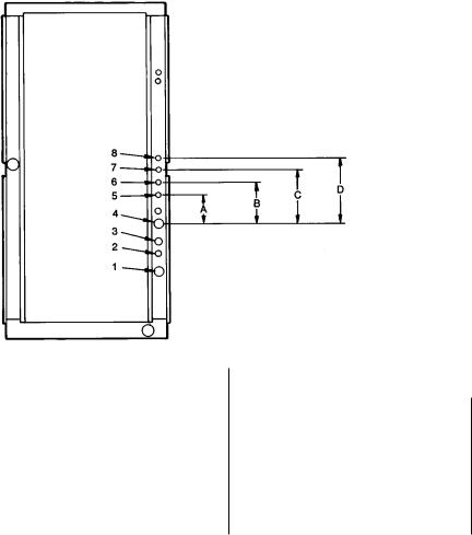
The 40RM Series units come with standard knockouts for refrigerant and chilled water piping. These knockouts are located on both sides of the unit for installation ¯exibility. The standard knockouts provide sufficient access to the unit's coils for all 40RM and some 40RMQ units, however, for 40RMQ016 and 40RMS units, additional holes must be ®eld-fabricated to accommodate the piping. See Fig. 4 for the positions and dimensions of the additional access holes required for these units, including hole diameters and drilling dimensions. Recommended access hole use is also listed for all units. Note that Fig. 4 shows the access holes on the control-box side of the unit; this is the side of the unit with the coil headers, so it is used most often for piping access.
Refrigerant Piping Ð See Tables 1A, 1B, 1D, 1E for refrigerant pipe connection sizes. For ease in brazing, it is recommended that all internal solder joints be made before unit is placed in ®nal position.
The 40RM and 40RMQ direct-expansion units have internal factory-installed thermostatic expansion valves (TXVs), distributors, and nozzles for use with R-22. See Table 2 for part numbers. Knockouts are provided in the unit corner posts for 40RM and 40RMQ008 and 012 refrigerant piping. The 40RMQ016 unit requires additional ®eld-fabricated piping access holes. See Fig. 4, which also lists recommended knockouts and access holes to use for each 40RM and 40RMQ unit size. Recommended ®ttings are listed in Table 3.
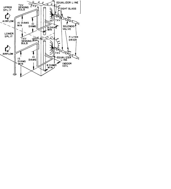
The sensor bulb capillary tubes must be routed from the TXVs inside the unit through one of the piping access holes. Clamp the TXV sensor bulb on a vertical portion of the suction line, outside the unit. See Fig. 5.
|
USE HOLE |
FIELD-FABRICATED HOLE DIAMETERS, |
|
|
FIELD-FABRICATED HOLE POSITION |
|||||||
UNIT |
|
in. (mm) |
|
|
|
|
DIMENSIONS, in. (mm) |
|
|
|||
NUMBERS |
|
|
|
|
|
|
|
|||||
|
No. 5 |
No. 6 |
No. 7 |
No. 8 |
|
|
A |
B |
C |
|
D |
|
|
|
|
|
|
||||||||
40RM007,008 |
1, 3 |
Ð |
Ð |
Ð |
Ð |
|
Ð |
|
Ð |
Ð |
Ð |
|
40RMQ008 |
|
|
||||||||||
|
|
|
|
|
|
|
|
|
|
|
|
|
40RM012-034 |
1, 2, 3, 4 |
Ð |
Ð |
Ð |
Ð |
|
Ð |
|
Ð |
Ð |
Ð |
|
40RMQ012 |
|
|
||||||||||
|
|
|
|
|
|
|
|
|
|
|
|
|
40RMS008-012 |
4, 5 |
13¤4 (44.5) |
Ð |
Ð |
Ð |
6.25 (158.8) |
Ð |
Ð |
Ð |
|||
40RMS014-024 |
4, 5, 6, 7 |
13¤4 (44.5) |
13¤4 (44.5) |
13¤4 (44.5) |
Ð |
3.0 |
(76.2) |
6.0 (152.4) |
10.5 (266.7) |
Ð |
||
40RMQ016 |
3*, 5, 6, 7 |
11¤8 (28.6) |
11¤8 (28.6) |
13¤4 (44.5) |
Ð |
3.25 (82.6) |
6.125 (155.6) |
10.38 (263.7) |
Ð |
|||
40RMS028,034 |
5, 6, 7, 8 |
21¤2 (63.5) |
21¤2 (63.5) |
21¤2 (63.5) |
21¤2 (63.5) 6.0 |
(152.4) |
9.625 (244.5) |
13.38 (339.9) |
17.0 (431.8) |
|||
*Must be enlarged from 11¤8 in. to 13¤4 inches.
NOTE: Access hole knockouts 1-4 are factory-supplied.
Fig. 4 Ð Refrigerant and Chilled Water Piping Access Holes
12
IMPORTANT: Never attach the sensor to the suction manifold. Do NOT mount the sensor on a trapped portion of the suction line.
40RM Series evaporator coils have a face-split design. Ensure that lower circuit of coil is ®rst on/last off when connected to the condensing unit and/or system controls. See Fig. 6.
External TXV equalizer connections are provided and factorybrazed into the coil suction manifolds.
If suction line must be horizontal, clamp bulb to suction line at least 45 degrees above bottom, at approximately the 4 o'clock or 8 o'clock position. See Fig. 7.
NOTE: The 40RMQ units are supplied with factory-installed thermostatic expansion valves and check valve bypasses. No extra piping connections or kits are required to install the 40RMQ with a 38AQS condensing unit in a heat pump system, however, some ®eld supplied components may be required. See the following two sections.
LEGEND
TXV Ð Thermostatic Expansion Valve
NOTE: Component location arrangement shown for ®eld installation of sight glasses, solenoid valves, ®lter driers, and TXV sensing bulbs. The TXVs and equalizer lines are factory installed.
Fig. 5 Ð Face-Split Coil Suction and
Liquid Line Piping (Typical)
FIRST ON/LAST OFF=B
VERTICAL INSTALLATION
FIRST ON/LAST OFF=A
HORIZONTAL INSTALLATION
Fig. 6 Ð Typical Evaporator Coil Connections
(40RM, 40RMQ)
LEGEND
TXV Ð Thermostatic Expansion Valve
NOTE: The 8 o'clock position is shown above.
Fig. 7 Ð TXV Sensing Bulb Location
13
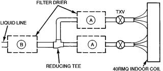
Table 2 Ð Factory-Installed Nozzle and Distributor Data
|
|
TXV |
DISTRIBUTOR |
FEEDER TUBES |
NOZZLE |
|||
UNIT |
|
PER DISTRIBUTOR* |
||||||
Qty Part No. |
Qty |
Part No. |
Qty |
Part No. |
||||
|
Qty Size (in.) |
|||||||
|
|
|
|
|
|
|
||
40RM007 |
1... |
XVE-5 |
1... |
1116 |
12 |
1... |
E5 |
|
40RM008 |
1... |
SVE-8 |
1... |
1126 |
15 |
1... |
C6 |
|
40RMQ008 |
1... |
SVE-8 |
1... |
1657 |
15 |
1... |
C6 |
|
40RM012 |
2... |
XVE-4 |
2... |
1115 |
9 |
2... |
E4 |
|
40RMQ012 |
2... |
XVE-4 |
2... |
1655 |
9 |
2... |
E4 |
|
40RM014 |
2... |
XVE-5 |
2... |
1115 |
9 |
2... |
E5 |
|
40RM016 |
2... |
XVE-8 |
2... |
1116 |
12 |
2... |
E6 |
|
40RMQ016 |
2... |
SVE-8 |
2... |
1126 |
16 |
2... |
C6 |
|
40RM024 |
2... |
XVE-10 |
2... |
1116 |
13 |
2... |
E8 |
|
40RM028 |
2... |
EBSVE-11 |
2... |
1126 |
15 |
2... |
C10 |
|
40RM034 |
2... |
SVE-15 |
2... |
1126 |
18 |
2... |
C12 |
|
|
|
|
|
|
|
|
|
|
* Feeder tube size is 1¤4 in. (6.35 mm).
NOTE: Hot gas bypass applications require ®eld-supplied auxiliary side connector.
38AQS008/40RMQ008 HEAT PUMP SYSTEM PIPING Ð Addition of a liquid solenoid valve (LLSV) is recommended when the piping system length exceeds 75 feet. The LLSV must be a bi-¯ow type suited for use in heat pump systems. The recommended valve is Sporlan model CB14S2 (5/8-in. ODF, 7/8-in. ODM) available from the Replacement Components Division as part number EF23JS-214. This solenoid valve requires Sporlan part no. MKC-2 coils that must be purchased locally. Wire the solenoid valve in parallel with the compressor contactor coil.
The LLSV must be installed at the outdoor unit with the ¯ow arrow pointed toward the outdoor unit (in-¯ow direction for the heating mode.)
FILTER DRIER REQUIREMENTS FOR 38AQS012/ 40RMQ012 AND 38AQS016/40RMQ016 HEAT PUMP SYSTEMS Ð The 38AQS012 and 016 units do not include ®lter driers. Filter driers must be ®eld-supplied and installed in 38AQS012/40RMQ012 and 38AQS016/ 40RMQ016 systems. The ®lter driers used with these systems must be bi-¯ow types suited for use in heat pump applications. The Replacement Component Division part numbers listed in Fig. 8 are recommended and available for ®eld installation.
LEGEND
TXV Ð Thermostatic Expansion Valve
RECOMMENDED FILTER DRIERS* (38AQS012,016/40RMQ SYSTEMS)
|
LIQUID |
|
|
|
|
UNIT |
LINE |
PART NO. |
QUANTITY |
FIGURE |
|
38AQS |
SIZE |
REQUIRED |
REFERENCE |
||
|
|||||
|
(in.) |
|
|
|
|
012 |
1¤2 |
P504-8084S |
2 |
A |
|
5¤8 |
P504-8165S |
1 |
B |
||
|
|||||
016 |
1¤2 |
P504-8084S |
2 |
A |
|
5¤8 |
P504-8085S |
2 |
A |
||
|
*Available from Carrier Replacement Components Division.
Fig. 8 Ð Filter Drier Requirements Ð 38AQS012/40RMQ012 and 38AQS016/40RMQ016 Heat Pump Systems
14
 Loading...