


40QNQ
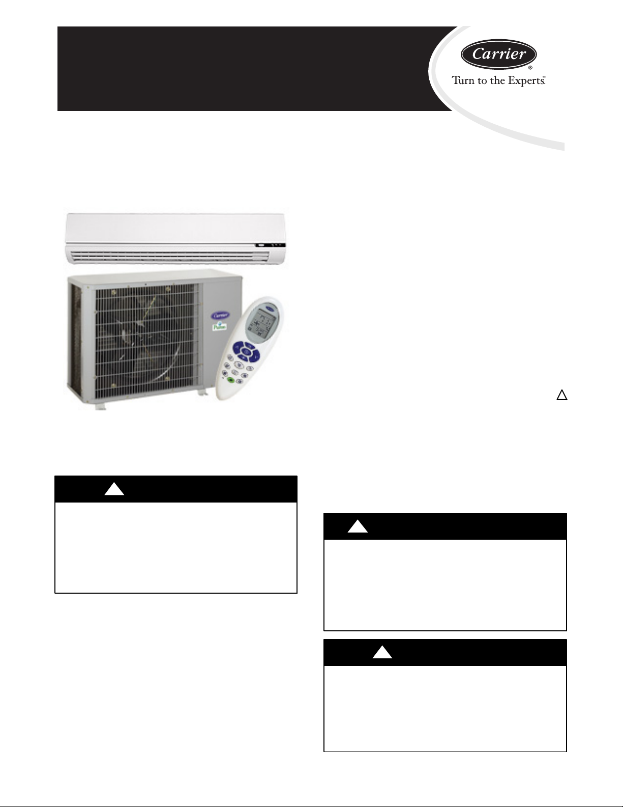
40QNC / 38HDF
40QNQ / 38QRF
High---Wall Du ct Free Split System
Sizes 018 to 036
Installation Instructions
40QNC, QNQ Unit
NOTE: Read the entire instruction manual before starting the
installation.
!
WARNING
UNIT OPERATION AND SAFETY HAZARD
Failure to follow this warning could result in personal injury or
equipment damage.
Puron refrigerant systems operate at higher pressures than
standard R--22 systems. To avoid damage to the unit or
possible personal injury, do not use R--22 service equipment or
components on Puron refrigerant equipment.
SAFETY CONSIDERATIONS
Improper installation, adjustment, alteration, service, maintenance,
or use can cause explosion, fire, electrical shock, or other
conditions which may cause death, personal injury, or property
damage. Consult a qualified installer, service agency, or your
distributor or branch for information or assistance. The qualified
installer or agency must use factory--authorized kits or accessories
when modifying this product. Refer to the individual instructions
packaged with the kits or accessories when installing.
Follow all safety codes. Wear safety glasses, protective clothing,
and work gloves. Use quenching cloth for brazing operations.
Have fire extinguisher available. Read these instructions
thoroughly and follow all warnings or cautions included in
literature and attached to the unit. Consult local building codes and
current editions of the National Electrical Code ( NEC ) NFPA 70.
In Canada, refer to current editions of the Canadian electrical code
CSA 22.1.
Recognize safety information. This is the safety--alert symbol
When you see this symbol on the unit and in instructions or
manuals, be alert to the potential for personal injury. Understand
these signal words; DANGER, WARNING, and CAUTION. These
words are used with the safety--alert symbol. DANGER identifies
the most serious hazards which will result in severe personal injury
or death. WARNING signifies hazards which could result in
personal injury or death. CAUTION is used to identify unsafe
practices which would result in minor personal injury or product
and property damage. NOTE is used to highlight suggestions
which will result in enhanced installation, reliability, or operation.
!
ELECTRICAL SHOCK HAZARD
Failure to follow this warning could result in personal
injury or death.
Before installing, modifying, or servicing system, main
electrical disconnect switch must be in the OFF
position. There may be more than 1 disconnect switch.
Lock out and tag switch with a suitable warning label.
WARNING
!
!
!
CAUTION
PERSONAL INJURY AND EQUIPMENT DAMAGE
HAZARD
Failure to follow this caution may result in personal injury
and / or equipment damage.
DO NOT operate the unit without a filter or with grille
removed.
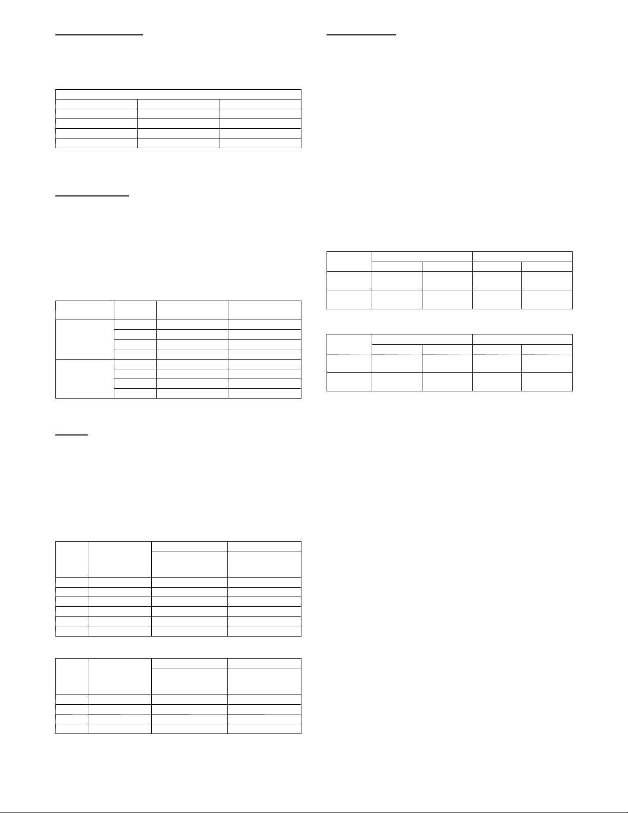
DIMENSIONS -- INDOOR
A08433
Model Size
In. (mm)
18k 42.5 (1080) 11.6 (295) 7.9 (201) 31 (14.1)
24k 42.5 (1080) 11.6 (295) 7.9 (201) 31 (14.1)
30k 57.5 (1461) 13.4 (340) 9.5 (241) 51 (23.2)
36k 57.5 (1461) 13.4 (340) 9.5 (241) 51 (23.2)
DIMENSIONS -- OUTDOOR
(FIELD PROVIDED AND INSTALLED)
W
H
In. (mm)
D
In. (mm)
Operating Weight
lb (kg)
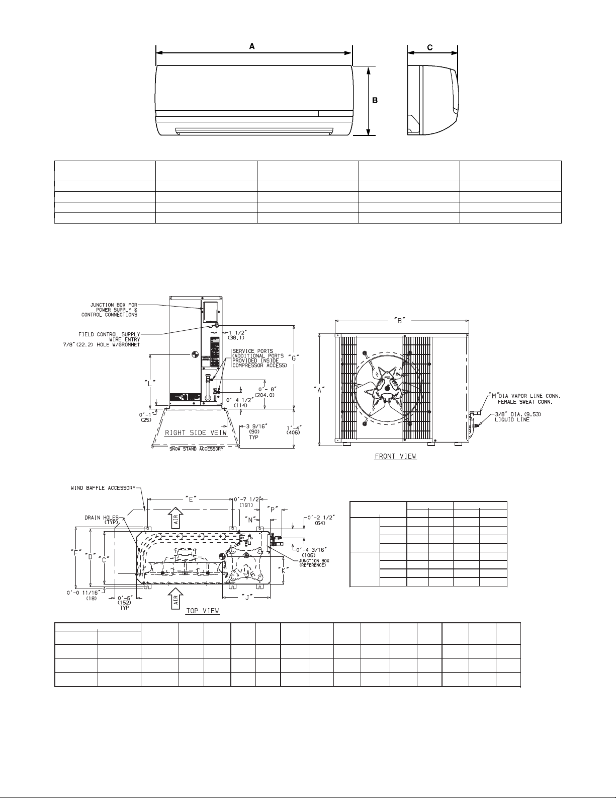
Fig. 1 -- 40QNC,QNQ Unit Dimensions
FEMALE SWEAT CONN.*
* Male flare connection for Heat Pumps
UNIT MODELS
38HDF
Unit Size
018 018
024,030 024 0.6
036 030,036 1.0
NOTE: Dimensions shown in feet-inches. Dimensions in ( ) are millimeters.
38QRF
Unit Size
CHASSIS
SIZE
(Reference)
0
ABCD EF G H J KL NP
1
2′-1
/8″ 3′-015/16″ 1′-29/16″ 1′-4″ 1′-117/16″ 1′-5
(638.2) (938.2) (369.9) (406.4) (595.3) (436.6) (435) (559.1) (330.2) (168.3) (285.8) (75) (152.4)
1
-7
/8″ 3′-015/16″ 1′-2
2′
(790.6) (938.2) (369.9) (406.4) (595.3) (436.6) (587.4) (711.5) (355.6) (171.5) (295.3) (75) (152.4)
3
3′-1
/16″ 3′-89/16″ 1′-51/16″1′-67/16″ 2′-61/
(944.6) (1131.9) (433.4) (468.3) (774.7) (498.5) (741) (865.5) (347.7) (206.4) (403.2) (88) (165.4)
UNIT SIZE
38HDF
38QRF
3
1
″ 1′-5
″ 1′-10″1′-1″ 0′
/
16
8
″1′-111/8″2′-4″ 1′-2″0′-63/
16
/8″ 2′-53/16″2′
-10
9
/
″ 1′-4″1′
16
/
3
7
-11
/16″ 1
/
′-5
5
1′-7
″
2
Fig. 2 -- 38HDF, QRF Unit Dimensions
2
018
024
030
036
018
024
030
036
1
″1′-111/16″ 0′
/
16
M OPERATING W T
in. mm lb kg
5
/815.88 166 75.3
5
/815.88 176 79.8
3
/419.05 187 84.8
3
/419.05 250 113.4
5
/815.88 166 75.3
5
/815.88 176 79.8
3
/419.05 187 84.8
3
/419.05 232 105.2
5
1
/8″0′-11
-6
-8
/4″0′-215/
16
5
/8″ 0
15
′-2
/16″0′-6
0′-11
″
4
1
/8″1′-37/8″ 0′-37/16″ 0′-61/
″ 0′-6
″
″
″
2
A08434
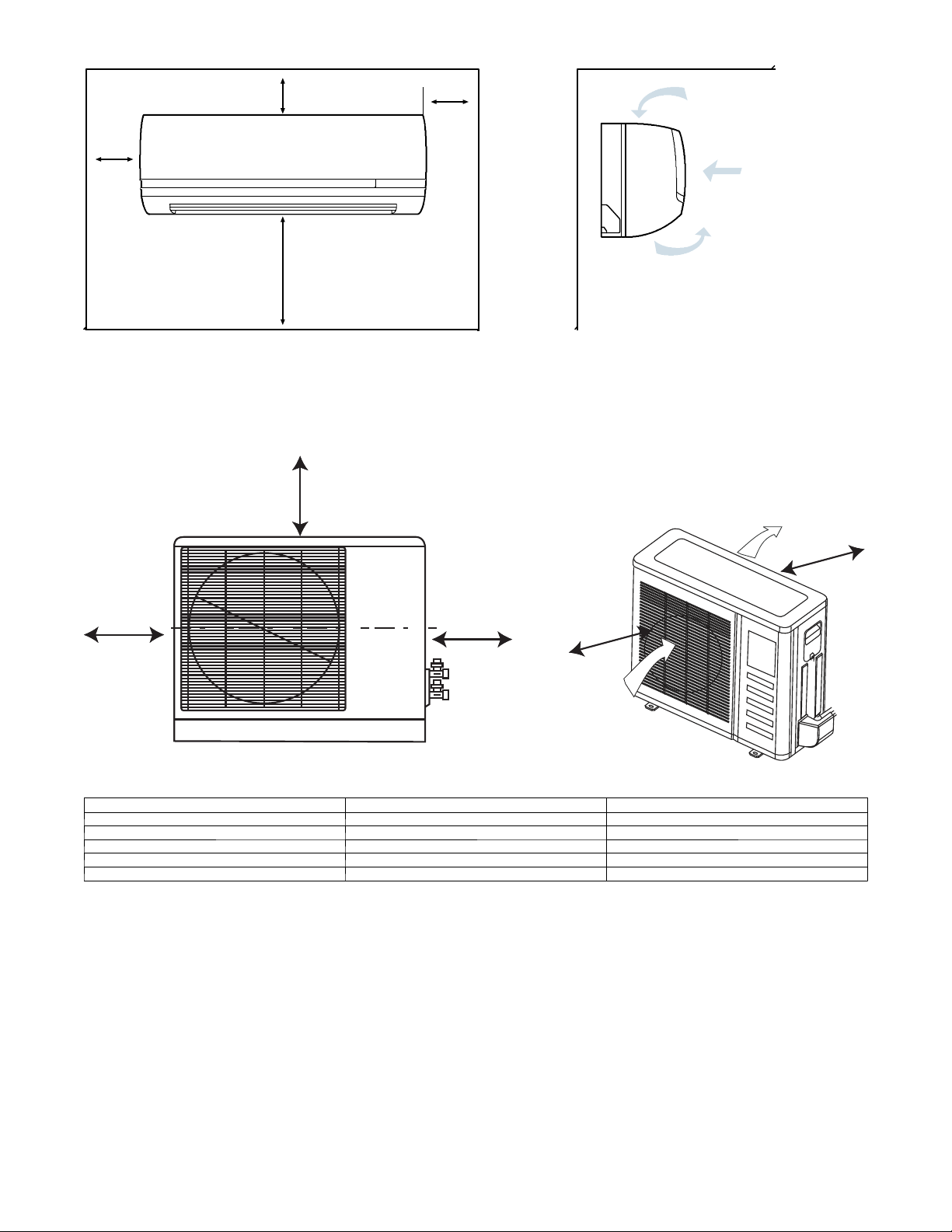
CLEARANCES -- INDOOR
4in.
min.
4in.
min.
80 in.
min.
CLEARANCES -- OUTDOOR
A
8in.
min.
A08357
Fig. 3 -- 40QNC,QNQ Unit Clearances
Air-outlet
D
B
UNIT Coil Facing Wall --- in. (mm )
A 24 (610)
B 36 (914)
C 36 (914)
D 6 (152)
E 6 (152)
Fig. 4 -- Outdoor Unit Clearance
E
C
Air-inlet
A08436
Fan Facing Wall --- in. (mm)
24 (610)
36 (914)
8 (203)
8 (203)
36 (914)
3
These installation instructions cover the installation of the matched
systems listed in table 2.
Parts List
Indoor Unit
The following items are included with the indoor unit:
Table 1 – Installation Materials
Description Qty Usage
Wall Mounting
Bracket
Screws, 4XL10 2
Screws, 5XL25 5/14*
Remote Control 1 For Controlling Unit
Remote Control
Holder
* 5 screws for unit sizes 18 a nd 24. 14 screws for unit sizes 30 and 36.
Outdoor Unit
The following items are included with the outdoor unit:
1 For Indoor Unit Installation
For Attaching The Remote Control
Holder To The Wall
For Attaching The Mounting Bracket To
The Wall
1 Holder For Remote C ontrol
38HDF018-036
A09499
Fig. 5 -- 38HDF018--036
SYSTEM REQUIREMENTS
Clearances
Allow sufficient space around the indoor and outdoor unit for
proper airflow circulation and servicing. Refer to Fig. 3 and Fig. 4
for minimum required clearances.
Piping: Piping and insulation is field supplied.
Piping Lengths
The minimum length between the indoor and outdoor units is 10 ft
(3 m). Refer to table 3 for the maximum lengths allowed.
Table 3 – Maximum Refrigerant LineLengths
Unit
Size
18K 200 ( 61) 65 (19.8) 200 (61)
24K 200 ( 61) 65 (19.8) 200 (61)
30K 200 ( 61) 65 (19.8) 200 (61)
36K 200 ( 61) 65 (19.8) 200 (61)
Note: For lengths greater than 25 ft (7.6 m), refer to the Duct Free Long
Pipe Sizes
Refer to table 4 for pipe sizes.
Note: Both lin es need to be insulated using at least 1/2 inch closed foam
Max Line
Length ft(m)
Line Guide.
Max Elevation (ID
over OD) ft(m)
Max Elevation (OD
over OD) ft(m)
Table4–PipeSizes
Unit Size M i x P h a s e --- i n Vapo r --- i n
18K 3/8 5/8
24K 3/8 5/8
30K 3/8 3/4
36K 3/8 3/4
insulation.
Pipe Sizes (in)
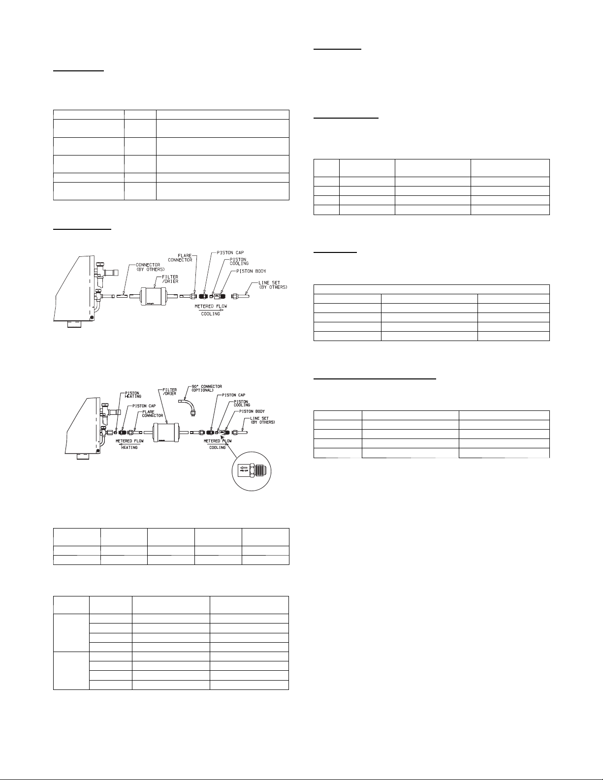
Fig. 6 -- 38QRF018--036
Model Filter Drier
38HDF n n n n
38QRF n n (qty 2) n n (qty 3)
* Multiple pistons. Quantity varies with size.
Piston
Cap
Pistons*
Connector
Table 2 – Matched Systems
System
Ty pe
Cooling
Only
Heat
Pump
Nominal
Capacity
018 3 8 H D F 0 1 8 --- --- --- 3 40QNC018024--- --- --- 3
024 3 8 H D F 0 2 4 --- --- --- 3 40QNC018024--- --- --- 3
030 3 8 H D F 0 3 0 --- --- --- 3 4 0 QNC030 --- --- --- 3
036 38HDF036 ------ --- 3/5/6 4 0 QNC036 --- --- --- 3
018 3 8 Q R F 0 1 8 --- --- --- 3 40QN Q 0 1 8 --- --- --- 3
024 3 8 Q R F 0 2 4 --- --- --- 3 40QN Q 0 2 4 --- --- --- 3
030 3 8 Q R F 0 3 0 --- --- --- 3 40QN Q 0 3 0 --- --- --- 3
036 38QRF036--- --- ---3/5/6 4 0 Q N Q036 --- --- --- 3
Outdoor
Unit
Indoor
Unit
Condensate Drain Pipe Sizes
Refertotable5fortherequiredsizes.
Table 5 – Drain Pipe Sizes
Unit Size Outside Diameter --- in Inside Diameter --- in
18K 5/8 7/16
24K 5/8 7/16
30K 3/4 5/9
36K 3/4 5/9
Note: Do not trap condensate pipe.
A09500
Flare
4
Refrigerant Charge
The 38HDF and 38QRF units can be matched with multiple
outdoor units and thus additional charge might be required when
matched with the 40QNC or 40QNQ units.
Table 6 – Additional Charge
Unit Size 38HDF 38QRF
018 1.2 (0.55) 0.8 (0.36)
024 1.0 (0.45) 0.5 (0.23)
030 2.4 (1.1) 0
Note: The above additional charge is required amount for line lengths up to
25 ft (7.6 m). For line lengths exceeding 25 ft (7.6 m), additional charge will
be required. Refer to the Duct Free Splits Long Line Guide.
036 0 0
Additional Charge lb (kg)
Metering Device
The metering device(s) for these systems is a type B Accurator
installed with the outdoor unit. One Accurator is required for the
cooling only system and two are required for the heat pump
systems. The Accurators are supplied with the outdoor unit.
However, since the same outdoor unit can be matched with
multiple indoor units, the correct Accurator must be selected. Refer
to Table 7 for the correct Accurator size.
Table 7 – Accurator Sizes
System Type Size
018 49 ---
Cooling Only
Heat Pumps
024 55 --030 63 --036 70 --018 49 45
024 55 49
030 63 53
036 70 63
Cooling
Accurator
Heating
Accurator
Power and Connecting Cables -- Field Supplied
Power:
S The indoor and outdoor units require a dedicated power supply.
S Consult local building codes, NEC (National Electric Code) or
CEC (Canadian Electric Code) for any special requirements.
S Use Table 8 for the electrical requirements for the outdoor units
and Table 9 for the indoor units to correctly size the cables and
disconnect switches.
Control Wiring
Thermostat wires should be used for control wiring between the
indoor and outdoor units. A two conductor cable is required for
the cooling only units and a seven conductor cable is required on
heat pumps. 18 AWG is recommended for any length up to 50 ft
(15.2 m). 16 AWG is recommended for lengths between 50 and
200 ft (15.2 and 61.0 m).
User Interface
The indoor unit is supplied with a wireless remote control. The
following accessories are also available
S Wall mounted control. Up to 6 units can be daisy chained and
controlled by one wired control.
S Zone manager capable of controlling up to 32 units divided up
to 8 different zones.
Operating Range
Ensure that the system operates within the application guidelines
shown in Table 10.
Cooling Operating Range
Maximum Minimum
Outdoor
Unit
Indoor
Unit
DB ° F (° C) WB ° F (° C) DB ° F (° C) WB ° F (° C)
125 (51.7) --- --- 55 (12.8) --- ---
90 (32.2) 74 (23.3) 62 (17.0) 56 (13)
Heating Operating Range
Maximum Minimum
Outdoor
Unit
Indoor
Unit
DB ° F (° C) WB ° F (° C) DB ° F (° C) WB ° F (° C)
75 (23.9) 67 (19.4) 17 (---8.3) --- ---
81 (27.2) --- --- 62 (17.0) --- ---
Accessories
An extensive list of field installed accessories is available for both
indoor and outdoor units. Identify what accessories, if any, are
required for the application at hand and consult the separate
installation instructions for the accessories. Some of the
accessories, especially on the indoor units, can be installed much
easier if planned ahead.
Table 8 – 38HDF / QRF Electrical Requirements
Unit
Size
018 208/230 ---1 ---60 12.1/20 12.1/20
024 208/230 ---1 ---60 16.8/25 16.8/25
030 208/230 ---1 ---60 18.4/30 18.4/30
036 208/230 ---1 ---60 23.8/40 23.8/40
036 208/230 ---3 ---60 18.0/30 18.0/30
036 46 0 --- 3 --- 6 0 8.3/15 8.3/15
Volt age
38HDF 38QRF
Min Ckt Amps/
Fuse HACR Bkr
Amps
Min Ckt Amps/
Fuse HACR Bkr
Amps
Table 9 – 40QNC / QNQ Electrical Requirements
Unit
Size
018 208/230 ---1 ---60 0.48/15 0.48/15
024 208/230 ---1 ---60 0.48/15 0.48/15
030 208/230 ---1 ---60 0.48/15 0.48/15
036 208/230 ---1 ---60 0.55/15 0.55/15
Volt age
40QNC 40QNQ
Min Ckt Amps/
Fuse HACR Bkr
Amps
Fuse HACR Bkr
Min Ckt Amps/
Amps
5
INSTALLATION
Complete Pre--installation Checks
1. Unpack Unit -- Store the indoor and outdoor units in the
original packaging until it is moved to the final site for installation.
2. Inspect Shipment -- Upon receipt of shipment, check the
indoor and outdoor units for damage. If there is any damage, forward claim papers directly to the transportation
company. Manufacturer is not responsible for damage incurred in transit.
3. Inspect Parts Supplied With Units – Check all items
against parts list (see Table 1). If any items are missing, notify your distributor or Carrier office. To prevent loss or
damage, leave all parts in original packages until installation.
Consider System Requirements
1. Consult local building codes and NEC for special installation requirements.
2. When deciding the location of the indoor and outdoor units,
ensure that the piping run does not exceed the allowed distances listed in Table 3.
3. Make sure the indoor and outdoor units are easily accessible
to electrical power.
4. Allow sufficient clearances for airflow, wiring, refrigerant
piping, and servicing the unit. See Fig. 3 and Fig. 4.
5. Condensate piping can be directed through the inside wall
to an approved drain or straight outside.
INSTALL INDOOR UNIT
Plan the installation carefully before you begin.
1. Select indoor unit location.
a. A location that can bear the weight of the unit.
b. Do not install indoor units near a direct source of heat
such as direct sunlight or a heating appliance.
c. Do not install units too close to humid conditions.
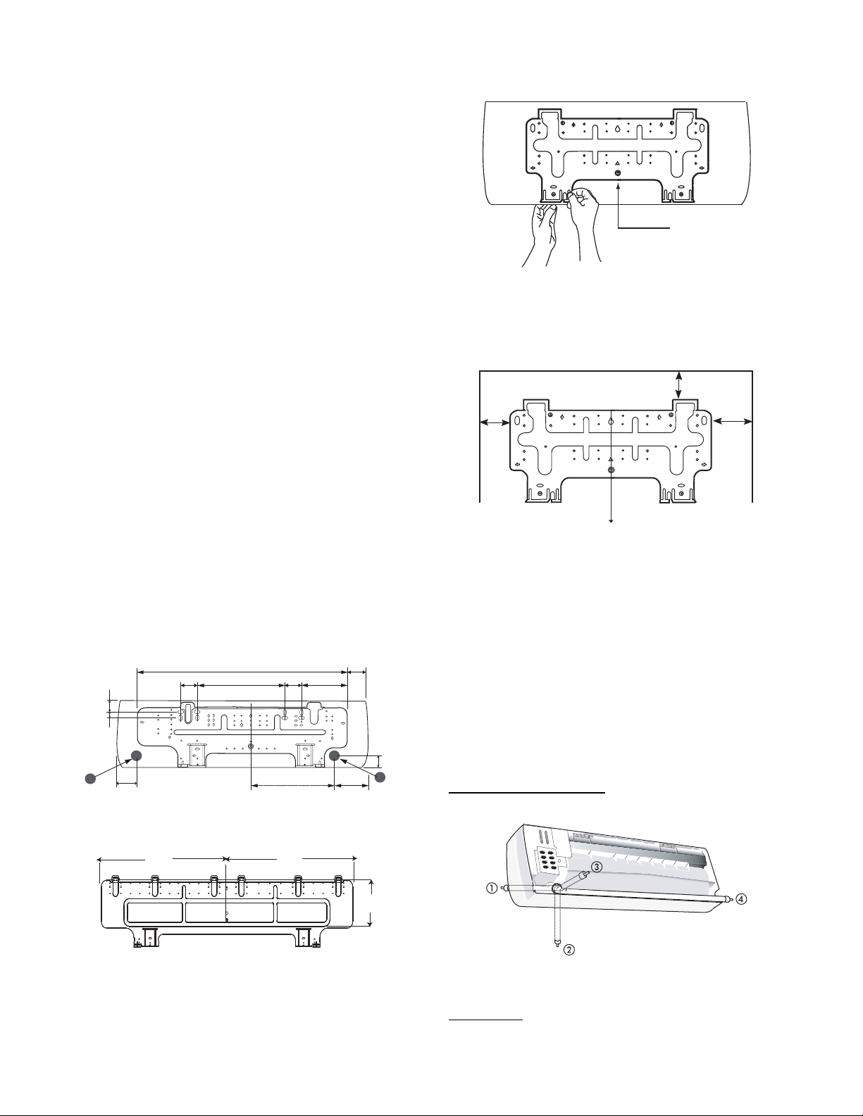
2. Install Mounting Plate
The factory supplied mounting plate will look like one of
the following depending on the size of the unit.
2.1"
(53.3)
1"
(25.4)
2"
A
(50.8)
2.8"
(71.1)
Note: Numbers in ( ) = mm
35.4” (899.2)
14.9" (378.5)
2.8"
(71.1)
13.8" (130.5)
Fig. 7 -- 40QNC, QNQ018,024 Mounting Plate
7.7" (195.6)
(129.5)
3.5"
(88.9)
5.1”
2.1"
(53.3)
B
A09046
a. Carefully remove the mounting plate which is attached
to the back of the unit by removing any screws and
pushing at the indicated pressure points at the bottom of
the unit.
Remove Screw
Fig. 9 -- Mounting Plate Screw Location
b. The mounting plate should be located horizontally and
level on the wall. All minimum spacing shown below
should be maintained.
5” (127) min.
12”
(304.8)
min.
Note: Numbers in ( ) = mm
Plumb line
18”
(457.2)
min.
Fig. 10 -- Minimum Spacing
c. Install the wall mounting bracket in a location that is
strong enough to withstand the weight of the unit.
d. If the wall is block, brick, concrete or similar material,
drill 0.2 in (5 mm) diameter holes and insert anchors for
the appropriate mounting screws.
e. Fasten the wall hanging bracket to the wall with 4 or
more screw anchors through the holes near the outer
edge of the bracket.
f. Install the wall hanging bracket flush to the wall, and
ensure the bracket does not move.
3. Drill hole in wall for interconnecting piping, drain, and wiring
Refrigerant Line Routing
Piping for indoor units can be routed as shown in Fig. 11.
A09048
A09049
27.1”
(688.3)
Measurements in ( ) = mm
27.2”
(690.9)
8.4” (213)
A09047
Fig. 8 -- 40QNC, QNQ030, 036 Mounting Plate
Before mounting the 40QNC, QNQ unit on the wall mounting
bracket, consider how the refrigerant piping will be routed.
Complete the following when installing the wall mounting bracket:
A08358A
Fig. 11 -- Refrigerant Line Routing
Rear Piping
Determine the pipe hole position using the mounting plate as a
template. Drill a 2--1/2 inch (63.5 mm) diameter hole in the wall at
6
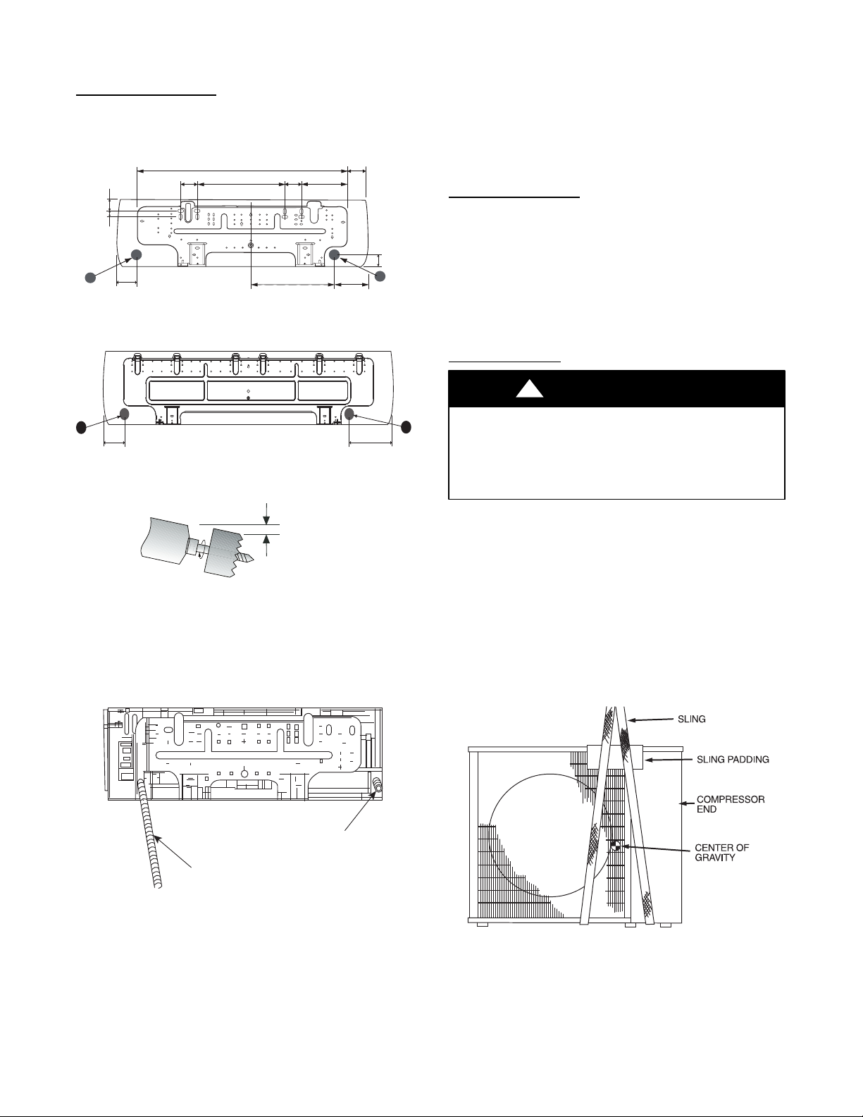
point A or B as shown in Fig. 12 or Fig. 13. Drill the hole at a
slope so that the outside end is 1/2 inch (13 mm) lower than inside
end to ensure optimal drainage. Refer to Fig. 14.
Side Or Bottom Piping
Remove the knockout in the unit and drill a 2--1/2 inch (63.5 mm)
hole where the pipe penetrates the structure using the guides given
above.
2.1"
(53.3)
1"
(25.4)
2"
A
(50.8)
2.8"
(71.1)
Note: Numbers in ( ) = mm
35.4” (899.2)
14.9" (378.5)
2.8"
(71.1)
13.8" (130.5)
Fig. 12 -- 40QNC, QNQ018, 024 Mounting Plate
7.7" (195.6)
(129.5)
3.5"
(88.9)
5.1”
2.1"
(53.3)
B
A09046
INSTALL OUTDOOR UNIT
The outdoor units can be installed on the ground, on the roof, or
mounted on a wall.
NOTE: Install the unit so that the coil does not face into
prevailing winds. If this is not possible and constant wind winds
above 25 mph are expected, use accessory wind baffle. See
installation instructions provided with accessory kit. Wind baffles
should also be used on all units with accessory low ambient
temperature control.
Mounting on Ground
1. Mount unit on a solid level concrete pad.
2. If a heat pump is being installed, use a field-- provided snow
stand or ice rack where prolonged subfreezing temperatures
or heavy snow occurs.
3. Position unit so water or ice from roof does not fall directly
onto unit.
4. On cooling only units, an accessory stacking kit can be used
when units are to be stacked. See installation instructions
provided with the accessory kit.
Mounting on Roof
!
CAUTION
A
2" 5.1"
Fig. 13 -- 40QNC, QNQ030, 036 Mounting Plate
1/2 in. (13 mm)
Min.
INDOOR
OUTDOOR
Fig. 14 -- Drill Hole at Slope
4. Relocate drain connection if necessary -- Determine if the
installation requires a left or a right hand drain exit and relocate the drain hose if necessary as shown in Fig. 15.
A09050
A07371
B
PERSONAL INJURY AND/OR EQUIPMENT
DAMAGE HAZARD
Failure to follow this caution may result in personal injury
and / or equipment damage.
Be sure unit panels are securely in place prior to rigging.
1. Rig the unit. Keep the unit upright and lift using a sling.
Use cardboard or padding under the sling, and spreader bars
to prevent sling damage to the unit. See Fig 16. See Fig. 2
for center of gravity reference
2. Mount unit on a solid concrete pad or platform.
3. Isolate unit and piping from structure
4. If a heat pump is being installed, use a field-- provided snow
stand or ice rack where prolonged subfreezing temperatures
or heavy snow occurs.
5. On cooling only units, an accessory stacking kit can be used
when units are to be stacked. See installation instructions
provided with accessory kit.
Drain Cap
Drain Hose
A08362
Fig. 15 -- Drain Hose and Cap Location
NOTE: If the condensate pump accessory is to be used, the drain
hose can be cut to provide space for the space for the condensate
pump reservoir in the back of the unit. The reservoir must be
installed at this time. Please refer to installation instructions
provided with the condensate pump accessory.
5. Place unit on a clean surface until you are ready to connect
the piping and wiring.
A07396
Fig. 16 -- Lifting Unit with Sling
7
Mounting Unit on Wall
The units can also be mounted on the wall using the accessory
mounting kit.
Complete Outdoor Refrigerant Piping Connections
Follow the following general guidelines:
1. Use refrigerant grade field – supplied tubing.
Refer to Table 4 for the correct line sizes.
2. Do not use less than 10 ft (93.05 m) of interconnecting
tubing.
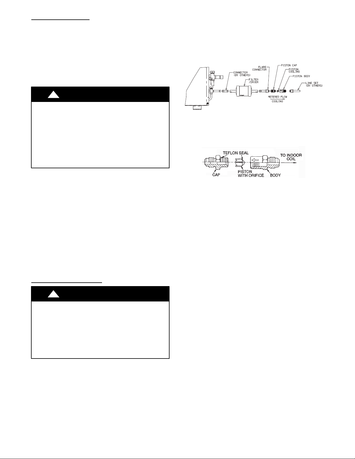
38HDF Units:
1. Assemble the connector tube to the factory supplied filter
drier by:
a. Braze the field supplied connector to the inlet of the
filter drier (see Fig. 17)
b. Braze the factory supplied flare connector to the outlet
end of the filter drier (see Fig.17)
!
UNIT DAMAGE HAZARD
Failure to follow this caution may result in equipment
damage or improper operation.
If any section of pipe is buried, there must be a 6 in. (152.4
mm) vertical rise to the valve connections on the outdoor
unit. If more than the recommended length is buried,
refrigerant may migrate to cooler, buried section during
extended periods of system shutdown. This causes
refrigerant slugging and could possibly damage the
compressor at start--up.
When more than 80 ft (24.4 m) of interconnecting tubing is used,
consult the Duct--Free Split System Long Line Application Guide
for required accessories.
3. Insulate both lines. A minimum of 1/2 inch foam pipe insulation is recommended.
4. Run the refrigerant tubes as directly as possible and avoid
unnecessary turns and bends.
5. Suspend refrigerant tubes to avoid damage to insulation or
tubes so they do not transmit vibration to the structure.
6. When passing refrigerant tubes through the wall, seal the
opening so rain and insects do not enter the structure. Leave
some slack in refrigerant tubes between structure and outdoor unit to absorb vibration.
NOTE: A fusible plug is located in unit suction line; do not cap
this plug. If local codes require additional safety devices, install as
directed.
CAUTION
Connection at Outdoor Unit
A09499
Fig. 17 -- 38HDF018--036 Connector Tube Assembly
2. Assemble the Accurator body (see Fig. 18) using the correct
factory supplied piston (refer to Table 7) .
NOTE: Arrow on AccuRater body points in free flow direction, away from the
indoor coil.
A09501
Fig. 18 -- AccuRater (bypass type) Metering Device
Components
3. Attach the complete Accurator assembly to the flare connection end of the filter drier
4. Braze the completed filter drier/Accurator assembly to the
liquid service valve.
5. Connect the field supplied line set to the filter drier/Accurator assembly and the suction valve. A sweat connection is
required at the suction valve and flareconnection is required
for the mixed phase line.
6. Insulate any exposed areas between the line set and the liquid valve.
!
UNIT DAMAGE HAZARD
Failure to follow this caution may result in equipment damage
or improper operation.
To prevent damage to unit or service valves observe the
following:
S A brazing shield MUST be used.
S Wrap service valves with wet cloth or use a heat sink
material.
CAUTION
8
 Loading...