


40QAC / 38HDR 40QAQ / 38QRR
Ceiling---Suspended Duct Free Split System Sizes 018 to 060
Installation Instructions
40QAC, QAQ Unit
the environmentally sound refrigerant
38HDR, QRR Unit
NOTE: Read the entire instruction manual before starting the installation.
!WARNING
UNIT OPERATION AND SAFETY HAZARD
Failure to follow this warning could result in personal injury or equipment damage.
Puron refrigerant systems operate at higher pressures than standard R-22 systems. To avoid damage to the unit or possible personal injury, do not use R-22 service equipment or components on Puron refrigerant equipment.
SAFETY CONSIDERATIONS
Improper installation, adjustment, alteration, service, maintenance, or use can cause explosion, fire, electrical shock, or other conditions which may cause death, personal injury, or property damage. Consult a qualified installer, service agency, or your distributor or branch for information or assistance. The qualified installer or agency must use factory-authorized kits or accessories when modifying this product. Refer to the individual instructions packaged with the kits or accessories when installing.
Follow all safety codes. Wear safety glasses, protective clothing, and work gloves. Use quenching cloth for brazing operations. Have fire extinguisher available. Read these instructions thoroughly and follow all warnings or cautions included in literature and attached to the unit. Consult local building codes and current editions of the National Electrical Code ( NEC ) NFPA 70. In Canada, refer to current editions of the Canadian electrical code CSA 22.1.
Recognize safety information. This is the safety-alert symbol !! When you see this symbol on the unit and in instructions or manuals, be alert to the potential for personal injury. Understand these signal words; DANGER, WARNING, and CAUTION. These words are used with the safety-alert symbol. DANGER identifies the most serious hazards which will result in severe personal injury or death. WARNING signifies hazards which could result in personal injury or death. CAUTION is used to identify unsafe practices which would result in minor personal injury or product and property damage. NOTE is used to highlight suggestions which will result in enhanced installation, reliability, or operation.
!WARNING
ELECTRICAL SHOCK HAZARD
Failure to follow this warning could result in personal injury or death.
Before installing, modifying, or servicing system, main electrical disconnect switch must be in the OFF position. There may be more than 1 disconnect switch. Lock out and tag switch with a suitable warning label.
!CAUTION
PERSONAL INJURY AND EQUIPMENT DAMAGE HAZARD
Failure to follow this caution may result in personal injury and / or equipment damage.
DO NOT operate the unit without a filter or with grille removed.
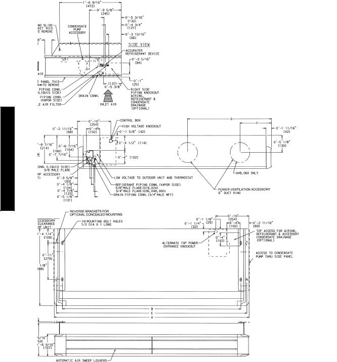
DIMENSIONS - INDOOR
NOTES:
1. Dimensions in [ ] are in millimeters.
2.  Direction of airflow.
3. Standard unit clearances are as follows:
• 0 in. on top and rear
• 3 in. on left side
• 12 in. on right side
• 36 in.on bottom
(When facing unit discharge.)
40QAC/38HDR -- 40QAQ/38QRR
|
|
|
|
|
|
|
|
|
|
|
|
|
|
|
|
A08580 |
|
|
|
|
|
|
|
|
|
|
|
|
|
|
|
|
|
UNIT |
WEIGHT (lb) |
A |
|
|
B |
|
|
|
E |
|
F |
|
G |
|
||
SIZE |
Cooling |
Heat |
ft in. |
mm |
ft |
in. |
mm |
ft |
in. |
|
mm |
ft |
in. |
mm |
ft in. |
mm |
Only |
Pump |
|
||||||||||||||
|
|
|
|
|
|
|
|
|
|
|
|
|
|
|
||
024 |
108 |
110 |
4---215/16 |
1294 |
3--- |
10 |
1169 |
4--- |
15/8 |
|
1260 |
|
— |
— |
1---95/8 |
549 |
036 |
117 |
119 |
4---1013/16 |
1493 |
4---57/8 |
1368 |
4--- |
91/2 |
|
1459 |
|
— |
— |
2---11/2 |
648 |
|
048 |
149 |
151 |
5---119/16 |
1817 |
5---65/8 |
1692 |
5---101/4 |
|
1783 |
1---97/8 |
555 |
3---31/16 |
992 |
|||
060 |
179 |
181 |
7---8 |
2336 |
7--- |
3 |
2211 |
7--- |
65/8 |
|
2302 |
1--- |
115/8 |
601 |
4---119/16 |
1512 |
Fig. 1 - 40QA Dimensions
2


 F,
F, 


 F.
F.
3
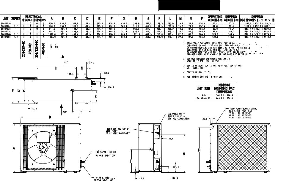
Fig. 2 - 38HDR Outdoor Unit Dimensions - English
40QAC/38HDR -- 40QAQ/38QRR
40QAC/38HDR -- 40QAQ/38QRR
X = YES
YES
O = NO
NO
AIR 
1.REQUIRED CLEARANCES: WITH COIL FACING
 WALL; ALLOW 152.4 MIN


 CLEARANCE ON COIL SIDE AND
 COIL END AND
 914.4 MIN CLEARANCE


ON COMPRESSOR END AND FAN SIDE. WITH FAN FACING WALL; ALLOW 203.2 MIN


 CLEARANCE ON FAN SIDE AND COIL END AND
 914.4 MIN CLEARANCE


ON COMPRESSOR END AND COIL SIDE. WITH
WITH MULTI UNIT APPLICATION;


 ARRANGE UNITS SO DISCHARGE OF ONE
 DOES NOT ENTER INLET OF ANOTHER.


2.MINIMUM OUTDOOR OPERATING AMBIENT IN COOLING


MODE IS 12.8 |
C, MAX. 51.7 |
C. |
3. SERIES DESIGNATION IS THE 13TH POSITION OF THE UNIT MODEL NUMBER. 

4.CENTER OF GRAVITY


5.ALL DIMENSIONS ARE IN "MM"
  UNLESS NOTED.


AIR 
4


 M VAPOR LINE CONN.

FEMALE SWEAT CONN. 
 9.53 LIQUID LINE

 FEMALE SWEAT CONN.
JUNCTION BOX FOR 
 POWER SUPLLY AND
 CONTROL CONNECTIONS
Fig. 3 - 38HDR Outdoor Unit Dimensions - SI
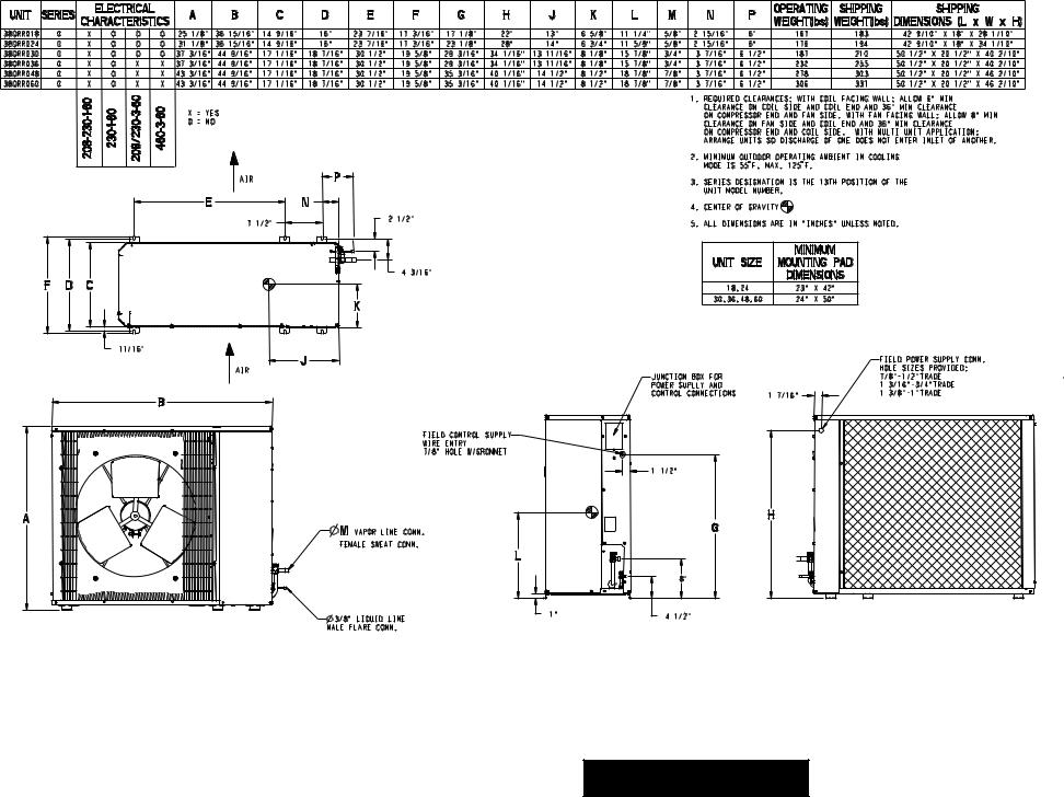
|
1. REQUIRED CLEARANCES: WITH COIL FACING WALL; ALLOW 6" MIN |
|||
X = YES |
CLEARANCE ON COIL SIDE AND COIL END AND 36" MIN CLEARANCE |
|||
ON COMPRESSOR END AND FAN SIDE. WITH FAN FACING WALL; ALLOW 8" MIN |
||||
O = NO |
||||
CLEARANCE ON FAN SIDE AND COIL END AND 36" MIN CLEARANCE |
||||
|
||||
|
ON COMPRESSOR END AND COIL SIDE. WITH MULTI UNIT APPLICATION; |
|||
|
ARRANGE UNITS SO DISCHARGE OF ONE DOES NOT ENTER INLET OF ANOTHER. |
|||
|
2. MINIMUM OUTDOOR OPERATING AMBIENT IN COOLING |
|||
|
MODE IS 55 |
F, MAX. 125 |
F. |
|
AIR |
3. SERIES DESIGNATION IS THE 13TH POSITION OF THE |
|||
|
||||
|
UNIT MODEL NUMBER. |
|
||
|
4. CENTER OF GRAVITY |
|
||
|
5. ALL DIMENSIONS ARE IN "INCHES" UNLESS NOTED. |
|||
|
|
|
FIELD POWER SUPPLY CONN. |
|
AIR |
|
|
HOLE SIZES PROVIDED: |
|
JUNCTION BOX FOR |
|
7/8"-1/2"TRADE |
||
|
|
|||
5 |
POWER SUPLLY AND |
|
1 3/16"-3/4"TRADE |
|
CONTROL CONNECTIONS |
1 7/16" |
1 3/8"-1"TRADE |
||
B |
||||
|
|
|||
|
|
|
||
FIELD CONTROL SUPPLY |
|
|
|
|
WIRE ENTRY |
|
|
|
|
7/8" HOLE W/GROMMET |
|
|
|
|
|
1 1/2" |
|
|
|
A |
|
H |
|
|
G |
|
|
||
M VAPOR LINE CONN. |
|
|
||
FEMALE SWEAT CONN. |
|
|
|
|
L |
|
|
|
|
|
8" |
|
|
|
1" |
4 1/2" |
|
|
|
3/8" LIQUID LINE |
|
|
|
|
MALE FLARE CONN. |
|
|
|
|
Fig. 4 - 38QRR Outdoor Unit Dimensions - English
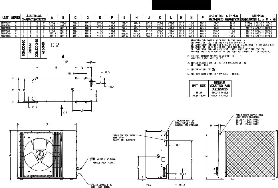
40QAC/38HDR -- 40QAQ/38QRR
40QAC/38HDR -- 40QAQ/38QRR
X = YES |
O = NO |
AIR |
AIR |
6 |
B |
A
1. REQUIRED CLEARANCES: WITH COIL FACING
 WALL; ALLOW 152.4
 MIN
MIN


 CLEARANCE ON COIL SIDE AND
 COIL END AND
 914.4 MIN CLEARANCE


ON COMPRESSOR END AND FAN SIDE. WITH FAN FACING WALL; ALLOW 203.2 MIN

 CLEARANCE ON FAN SIDE AND COIL END AND
 914.4 MIN CLEARANCE


ON COMPRESSOR END AND COIL SIDE. WITH MULTI UNIT APPLICATION;


 ARRANGE UNITS SO DISCHARGE OF ONE
 DOES NOT ENTER INLET OF ANOTHER.


2. MINIMUM OUTDOOR OPERATING AMBIENT IN COOLING


MODE IS 12.8 |
C, MAX. 51.7 |
C. |
3. SERIES DESIGNATION IS THE 13TH POSITION OF THE UNIT MODEL NUMBER. 


4. CENTER OF GRAVITY


5. ALL DIMENSIONS ARE IN "MM" UNLESS NOTED.

|
FIELD POWER SUPPLY CONN. |
|
|
HOLE SIZES PROVIDED: |
|
JUNCTION BOX FOR |
22.22 - 12.70 TRADE |
|
30.16 - 19.05 TRADE |
||
POWER SUPLLY AND |
||
34.92 - 25.40 TRADE |
||
CONTROL CONNECTIONS |
||
36.5 |
|
FIELD CONTROL SUPPLY |
|
|
WIRE ENTRY |
|
|
22.22 HOLE W/GROMMET |
|
|
|
38.1 |
M VAPOR LINE CONN. |
|
H |
|
G |
|
FEMALE SWEAT CONN. |
|
|
|
|
|
|
L |
|
|
|
203.2 |
9.53 LIQUID LINE |
25.4 |
114.3 |
MALE FLARE CONN. |
|
|
Fig. 5 - 38QRR Outdoor Unit Dimensions - SI
These installation instructions cover the installation of the matched systems listed in table 2.
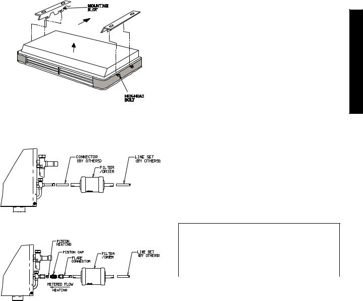
Parts List
Indoor Unit
The following items are included with the indoor unit:
Table 1 – Installation Materials
Part No. |
Name of Part |
Qty. |
||||||||||||
1 |
Side Panels |
2 |
||||||||||||
2 |
Hex Head Bolts |
4 |
||||||||||||
3 |
Mounting Bracket |
2 |
||||||||||||
4 |
|
Pistons |
1 |
|||||||||||
5 |
Installation Template |
1 |
||||||||||||
6 |
Adapter Tubes |
2 |
||||||||||||
|
|
|
|
|
|
|
|
|
|
|
|
|
|
|
|
|
|
|
|
|
|
|
|
|
|
|
|
|
|
|
|
|
|
|
|
|
|
|
|
|
|
|
|
|
A09532
Fig. 6 - Hanging Fan Coil Unit
Outdoor Unit
The following items are included with the outdoor unit:
A09536
Fig. 7 - 38HDR018-036
|
|
|
|
A09537 |
|
|
Fig. 8 - 38QRR018-036 |
|
|||
|
|
|
|
|
|
Model |
Filter Drier |
Piston |
Pistons |
Flare |
|
Cap |
Connector |
||||
|
|
|
|||
38HDR |
n |
--- |
--- |
--- |
|
38QRR |
n |
n |
n |
n |
|
Table 2 – Matched Systems
System |
Nominal |
Outdoor Unit |
Indoor Unit |
|
||
Type |
Capacity |
|
||||
|
|
|
|
|||
|
|
|
|
|
|
|
|
018 |
38HDR018 |
3 |
40QAC024--- --- --- |
3 |
|
|
* |
|
||||
|
|
|
|
|
||
|
|
|
|
|
|
|
Cooling |
024 |
38HDR024--- --- |
---3 |
40QAC024--- --- --- |
3 |
|
|
|
|
|
|
||
036 |
38HDR036--- --- --- |
3/5/6 |
40QAC036--- --- --- |
3 |
||
|
030 |
38HDR030--- --- |
---3 |
40QAC036--- --- --- |
3 |
|
|
|
|
|
|
|
|
|
048 |
38HDR048--- --- --- |
3/5/6 |
40QAC048--- --- --- |
3 |
|
|
|
|
|
|
|
|
|
060 |
38HDR060--- --- --- |
3/5/6 |
40QAC060--- --- --- |
3 |
|
|
|
|
|
|
|
|
|
018 |
38QRR018--- --- |
---3 |
40QAQ024--- --- --- |
3 |
|
|
|
|
|
|
|
|
Pumps |
024 |
38QRR024--- --- |
---3 |
40QAQ024--- --- --- |
3 |
|
|
|
|
|
|
||
030 |
38QRR030 |
3 |
40QAQ036 |
3 |
||
|
||||||
|
|
|
|
|
|
|
Heat |
036 |
38QRR036--- --- --- |
3/5/6 |
40QAQ036--- --- --- |
3 |
|
|
|
|
|
|
||
048 |
38QRR048--- --- --- |
3/5/6 |
40QAQ048--- --- --- |
3 |
||
|
|
|
|
|
|
|
|
060 |
38QRR060--- --- --- |
3/5/6 |
40QAQ060--- --- --- |
3 |
|
|
|
|
|
|
|
|
*Units must be configured for 1---1/2 ton operation. Refer to instructions on page 9.
SYSTEM REQUIREMENTS
Clearances
Allow sufficient space around the indoor and outdoor unit for proper airflow circulation and servicing. Refer to Fig. 1 through Fig. 5 for minimum required clearances.
Piping: Piping and insulation is field supplied.
Piping Lengths
The minimum length between the indoor and outdoor units is 10 ft (3 m). Refer to table 3 for the maximum lengths allowed.
Table 3 – Maximum Refrigerant Line Lengths
Unit |
Max Line |
Max Elevation (ID |
Max Elevation (OD |
Size |
Length ft(m) |
over OD) ft(m) |
over OD) ft(m) |
18K |
200 (61) |
65 (19.8) |
200 (61) |
24K |
200 (61) |
65 (19.8) |
200 (61) |
30K |
200 (61) |
65 (19.8) |
200 (61) |
36K |
200 (61) |
65 (19.8) |
200 (61) |
48K |
200 (61) |
65 (19.8) |
200 (61) |
60K |
200 (61) |
65 (19.8) |
200 (61) |
Note:For lengths greater than 25 ft (7.6 m), refer to the Duct Free Long Line Guide.
Pipe Sizes
Refer to table 4 for pipe sizes.
Table 4 – Pipe Sizes
PIPE SIZES (in)
Unit Size |
Liquid Phase |
|
Vapor |
|
38HDR |
|
38QRR |
||
|
|
|
||
18 |
3/8 |
5/8 |
|
5/8 |
24 |
3/8 |
5/8 |
|
5/8 |
30 |
3/8 |
3/4 |
|
3/4 |
36 |
3/8 |
3/4 |
|
3/4 |
48 |
3/8 |
7/8 |
|
3/4 |
60 |
3/8 |
7/8 |
|
3/4 |
Note:On heat pumps, both lines need to be insulated using at least 1/2 inch closed foam insulation.
40QAC/38HDR -- 40QAQ/38QRR
7
40QAC/38HDR -- 40QAQ/38QRR
Refrigerant Charge
The 38HDR and 38QRR units can be matched with multiple outdoor units and thus additional charge might be required when matched with the 40QAC or 40QAQ units.
Table 5 – Additional Charge
|
Additional Charge lb. (kg.) |
|
Unit Size |
38HDR |
38QRR |
018 |
0.7 (0.32) |
0.7 (0.32) |
024 |
1.3 (0.59) |
0.8 (0.36) |
030 |
1.4 (0.64) |
0 |
036 |
0.2 (0.1) |
0.5 (0.23) |
048 |
0.2 (0.1) |
0 |
060 |
0.5 (0.23) |
0 |
Note:The above additional charge is required amount for line lengths up to 25 ft (7.6 m). For line lengths exceeding 25 ft (7.6 m), additional charge will be required. Refer to the Duct Free Splits Long Line Guide.
Metering Device
The 40QAC and 40QAQ units use an accurator or a TXV as shown in Table 6.
Table 6 – Accurator Sizes
Unit Size |
Cooling Only |
Heat Pumps |
||
40QAC |
40QAQ |
38QRR |
||
|
||||
018 |
TVX |
49 |
40 |
|
024 |
TVX |
55 |
43 |
|
030 |
TVX |
65 |
55 |
|
036 |
TVX |
70 |
63 |
|
048 |
TVX |
80 |
73 |
|
060 |
TVX |
TXV |
80 |
|
NOTE: Pistons are supplied with either the indoor or outdoor units.
Power and Connecting Cables - Field Supplied
Power:
S The main power is supplied to both the indoor and outdoor
units.
SConsult local building codes, NEC (National Electric Code) or CEC (Canadian Electric Code) for any special requirements.
SUse Table 7 for the electrical requirements for the outdoor units and Table 8 for the indoor units to correctly size the cables and disconnect switches.
Control Wiring
Thermostat wires should be used for control wiring between the indoor and outdoor units. A two conductor cable is required for the cooling only units and a seven conductor cable is required on heat pumps. 18 AWG is recommended for any length up to 200 ft (61.0 m).
User Interface - Finished Goods Accessory
Any of the following three thermostats can be used depending on the type of system on hand and the desired features. Refer to Table 9 to select the proper thermostat.
Table 7 – 38HDR / QRR Electrical Requirements
|
|
|
38HDR |
|
38QRR |
|
UNIT SIZE |
V---PH---Hz |
MIN CKT AMPS |
|
FUSE/HACR BKR |
MIN CKT AMPS |
FUSE/HACR BKR AMPS |
|
|
|
AMPS |
|||
|
|
|
|
|
|
|
|
|
|
|
|
|
|
018 |
208/230---1---60 |
12.1 |
|
20 |
12.1 |
20 |
|
|
|
|
|
|
|
024 |
208/230---1---60 |
17.7 |
|
25 |
18.8 |
30 |
|
|
|
|
|
|
|
030 |
208/230---1---60 |
19.1 |
|
30 |
17.5 |
30 |
|
|
|
|
|
|
|
|
208/230---1---60 |
19.1 |
|
30 |
20.9 |
30 |
036 |
|
|
|
|
|
|
208/230---3---60 |
13.0 |
|
20 |
14.1 |
20 |
|
|
460---3---60 |
7.9 |
|
15 |
7.9 |
15 |
|
|
|
|
|
|
|
|
208/230---1---60 |
26.4 |
|
40 |
34.6 |
50 |
048 |
|
|
|
|
|
|
208/230---3---60 |
17.9 |
|
25 |
22.4 |
30 |
|
|
|
|
|
|
|
|
|
460---3---60 |
8.4 |
|
15 |
10.0 |
15 |
|
|
|
|
|
|
|
|
208/230---1---60 |
34.5 |
|
60 |
34.5 |
60 |
060 |
|
|
|
|
|
|
208/230---3---60 |
21.5 |
|
30 |
23.6 |
40 |
|
|
|
|
|
|
|
|
|
460---3---60 |
10.6 |
|
15 |
10.6 |
15 |
|
|
|
|
|
|
|
Table 8 – 40QAC / QAQ Electrical Requirements
UNIT |
VOLTAGE |
|
40QAC |
|
40QAQ |
||
V---Ph---60 Hz |
MCA |
|
MOCP |
MCA |
|
MOCP |
|
|
|
|
|||||
|
|
|
|
|
|
|
|
024 |
208/230---1 |
0.63 |
|
15.0 |
9.29 |
|
15.0 |
|
|
|
|
|
|
|
|
036 |
208/230---1 |
1.60 |
|
15.0 |
17.70 |
|
20.0 |
|
|
|
|
|
|
|
|
048 |
208/230---1 |
2.00 |
|
15.0 |
23.80 |
|
25.0 |
|
|
|
|
|
|
|
|
060 |
208/230---1 |
3.30 |
|
15.0 |
28.70 |
|
30.0 |
|
|
|
|
|
|
|
|
Table 9 – Thermostat Selection
|
|
|
System Type |
|
|
|
Model Number |
Cooling Only & HP |
Cooling Only |
Cooling Only |
|
|
|
53DFS250---SL |
53DFS250---FS |
53DFST2---NP |
|
Features |
7 Day Programmable |
√ |
√ |
--- |
|
5+1+1 Day Programmable |
--- |
--- |
√ |
||
|
|||||
|
Remote Room Sensor |
√ |
√ |
|
|
|
Dry Contact Equipped |
√ |
√ |
--- |
8
 Loading...