


Carrier 39LE, 39LF, 39LA, 39LC, 39LH03-25 User Manual
...39LA,LB,LC,LD,LF,LG,LH03-25 Indoor Air-Handling Units
Installation, Start-Up and
Service Instructions
CONTENTS
Page
SAFETY CONSIDERATIONS . . . . . . . . . . . . . . . . . . . . . . . . . . . .1
INTRODUCTION . . . . . . . . . . . . . . . . . . . . . . . . . . . . . . . . . . . . . . 2,3 Unit Identification. . . . . . . . . . . . . . . . . . . . . . . . . . . . . . . . . . . . . . .2
PREINSTALLATION . . . . . . . . . . . . . . . . . . . . . . . . . . . . . . . . . . .4-7 Rigging . . . . . . . . . . . . . . . . . . . . . . . . . . . . . . . . . . . . . . . . . . . . . . . . .4 Suspended Units . . . . . . . . . . . . . . . . . . . . . . . . . . . . . . . . . . . . . . .4 Service Clearance . . . . . . . . . . . . . . . . . . . . . . . . . . . . . . . . . . . . . .4 Condensate Drain . . . . . . . . . . . . . . . . . . . . . . . . . . . . . . . . . . . . . .4 External Vibration Isolators. . . . . . . . . . . . . . . . . . . . . . . . . . . . .4
INSTALLATION . . . . . . . . . . . . . . . . . . . . . . . . . . . . . . . . . . . . . .8-29 Mixing Box . . . . . . . . . . . . . . . . . . . . . . . . . . . . . . . . . . . . . . . . . . . . .8 Condensate Drain . . . . . . . . . . . . . . . . . . . . . . . . . . . . . . . . . . . . . .8 Inlet Guide Vane Actuators . . . . . . . . . . . . . . . . . . . . . . . . . . . 10 Install Fan Motor. . . . . . . . . . . . . . . . . . . . . . . . . . . . . . . . . . . . . . .11
Install Sheaves on Motor and Fan Shafts . . . . . . . . . . . . . .11
Install V-Belts . . . . . . . . . . . . . . . . . . . . . . . . . . . . . . . . . . . . . . . . . 12
Water and Steam Piping Recommendations . . . . . . . . . . 14
Coil Freeze-Up Protection . . . . . . . . . . . . . . . . . . . . . . . . . . . . 14
Refrigerant Piping, Direct Expansion
(DX) Coils . . . . . . . . . . . . . . . . . . . . . . . . . . . . . . . . . . . . . . . . . . 17 Electric Heaters. . . . . . . . . . . . . . . . . . . . . . . . . . . . . . . . . . . . . . . 25 Discharge Modification . . . . . . . . . . . . . . . . . . . . . . . . . . . . . . . 28
START-UP. . . . . . . . . . . . . . . . . . . . . . . . . . . . . . . . . . . . . . . . . . . 29,30 Check List . . . . . . . . . . . . . . . . . . . . . . . . . . . . . . . . . . . . . . . . . . . . 29
SERVICE . . . . . . . . . . . . . . . . . . . . . . . . . . . . . . . . . . . . . . . . . . .30-38 General . . . . . . . . . . . . . . . . . . . . . . . . . . . . . . . . . . . . . . . . . . . . . . . 30 Fan Motor Replacement . . . . . . . . . . . . . . . . . . . . . . . . . . . . . . 30 Coil Cleaning . . . . . . . . . . . . . . . . . . . . . . . . . . . . . . . . . . . . . . . . . 30
Winter Shutdown (Chilled Water Coil Only) . . . . . . . . . . . 30
Field-Installed Coils . . . . . . . . . . . . . . . . . . . . . . . . . . . . . . . . . . 31 Coil Removal . . . . . . . . . . . . . . . . . . . . . . . . . . . . . . . . . . . . . . . . . 31 Changing Coil Hand . . . . . . . . . . . . . . . . . . . . . . . . . . . . . . . . . . 35 Filters. . . . . . . . . . . . . . . . . . . . . . . . . . . . . . . . . . . . . . . . . . . . . . . . . 36 Fan Shaft Bearing Removal . . . . . . . . . . . . . . . . . . . . . . . . . . . 36 Fan and Shaft Removal . . . . . . . . . . . . . . . . . . . . . . . . . . . . . . . 38 Lubrication . . . . . . . . . . . . . . . . . . . . . . . . . . . . . . . . . . . . . . . . . . . 38
METRIC CONVERSION CHART . . . . . . . . . . . . . . . . . . . . . . . 39
SAFETY CONSIDERATIONS
Air-handling equipment is designed to provide safe and reliable service when operated within design specifications. To avoid injury to personnel and damage to equipment or property when operating this equipment, use good judgment and follow safe practices as outlined below.
NEVER enter an enclosed fan cabinet or reach into a unit while the fan is running.
LOCK OPEN AND TAG the fan motor power disconnect switch before working on a fan. Take fuses with you and note removal on tag. Electric shock can cause personal injury or death.
LOCK OPEN AND TAG the electric heat coil power disconnect switch before working on or near heaters.
CHECK the assembly and component weights to be sure that the rigging equipment can handle them safely. Note also, the centers of gravity and any specific rigging instructions.
CHECK for adequate ventilation so that fumes will not migrate through ductwork to occupied spaces when welding or cutting inside air-handling unit cabinet or plenum.
WHEN STEAM CLEANING COILS be sure that the area is clear of personnel.
DO NOT attempt to handle access covers and removable panels on outdoor units when winds are strong or gusting until you have sufficient help to control them. Make sure panels are properly secured while repairs are being made to a unit.
DO NOT remove access panel fasteners until fan is completely stopped. Pressure developed by a moving fan can cause excessive force against the panel which can injure personnel.
DO NOT work on dampers until their operators are disconnected.
BE SURE that fans are properly grounded before working on them.
SECURE drive sheaves with a rope or strap before working on a fan to ensure that rotor cannot free-wheel.
DO NOT restore power to unit until all temporary walkways inside components have been removed.
NEVER pressurize equipment in excess of specified test pressures.
PROTECT adjacent flammable material when welding or flame cutting. Use sheet metal or asbestos cloth to contain sparks. Have a fire extinguisher at hand and ready for immediate use.
IMPORTANT: The installation of air-handling units and all associated components, parts, and accessories which make up the installation and subsequent maintenance shall be in accordance with the regulations of ALL authorities having jurisdiction and MUST conform to all applicable codes. It is the responsibility of the installing contractor to determine and comply with ALL applicable codes and regulations. Field-supplied motors should be Underwriters Laboratories (UL) or Canadian Standards Association (CSA) approved. Field wiring must comply with National Electrical Code (NEC) and all local requirements.
Manufacturer reserves the right to discontinue, or change at any time, specifications or designs without notice and without incurring obligations.
Catalog No. 533-932 |
Printed in U.S.A. |
Form 39L-6SI |
Pg 1 |
1110 |
2-04 |
Replaces: 39L-5SI |
INTRODUCTION
Unit Identification — The 39L units are identified by the 18-digit part number listed on the serial plate. The part number describes all component, coil, motor, drive, and control selections. See Fig. 1-3 for unit identification.
Fig. 1 — Unit Identification
39L C 10 GK C H E A C G - A
Due to the complexity of the (18 position) 39L model number, use the “verify model number” function in the AHUBuilder® software for a detailed model explanation. The description below can be used as a general model guide.
Pos. 1-3: Unit Type — 39L Air Handler
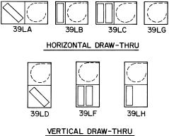
Pos. 4: Unit Model — how the unit is configured. Refer to Fig. 3. Pos. 5-6: Unit Size — Ranges from 03 to 25.
Pos. 7-8: Draw-Thru Options — Includes the sections that will make up the unit.
Pos. 9-12: Coil Type and Arrangement — Describes the coil type (chilled water, CX, heating only, etc.), fins, rows and circuit information.
Pos. 13-15: Fans — Describes fan discharge, fan speed, and motor information.
Pos. 16: Controls — Describes the AirManager™ control offering (CV, VAV) and the components that they include.
Pos. 17: F1/F2 Motors — Depending upon positions 13 and 17, F1 or F2 motors may be substituted for top mounted motor conduit boxes.
Pos. 18: Special Order — Allows copper fin coils and/or .025 in. wall tubes.
LEGEND
CV — Constant Volume
DX — Direct Expansion
VAV — Variable Air Volume
Fig. 2 — 39L Model Number
2

3
LEGEND
COMB. — Combination
PH — Preheat
POS. — Position
Factory-installed option components
Fig. 3 — Position 4, Unit Configuration Model (Component Sequence Also Shown)

PREINSTALLATION
1.Check items received against packing list. Notify Carrier of any discrepancy.
2.Refer to Fig. 4 for service area requirements.
3.To transfer unit from truck to storage site, refer to rigging details in Fig. 5 and section on unit rigging for proper handling. See Table 1 for component weights.
If a fork lift truck is used, lift only from heavy end of skid. Minimum recommended fork length is 48 inches.
4.Do not stack unit components or accessories during storage. Stacking can cause damage or deformation.
5.If unit is to be stored for more than 2 weeks prior to installation, observe the following precautions:
a.Choose a dry storage site that is reasonably level and sturdy to prevent undue stress or permanent damage to the unit structure or components. Do not store unit on vibrating surface. Damage to stationary bearings can occur. Set unit off ground if in heavy rain area.
b.Remove all fasteners and other small parts from jobsite to minimize theft. Tag and store parts in a safe place until needed.
c.Cover entire unit with a tarp or plastic coverall. Extend cover under unit if stored on ground. Secure cover with adequate tiedowns or store indoors. Be sure all coil connections have protective shipping caps.
d.Monthly — Remove tarp from unit, enter fan section through access door or through fan inlet, and rotate fan and motor slowly by hand to redistribute the bearing grease and to prevent bearing corrosion.
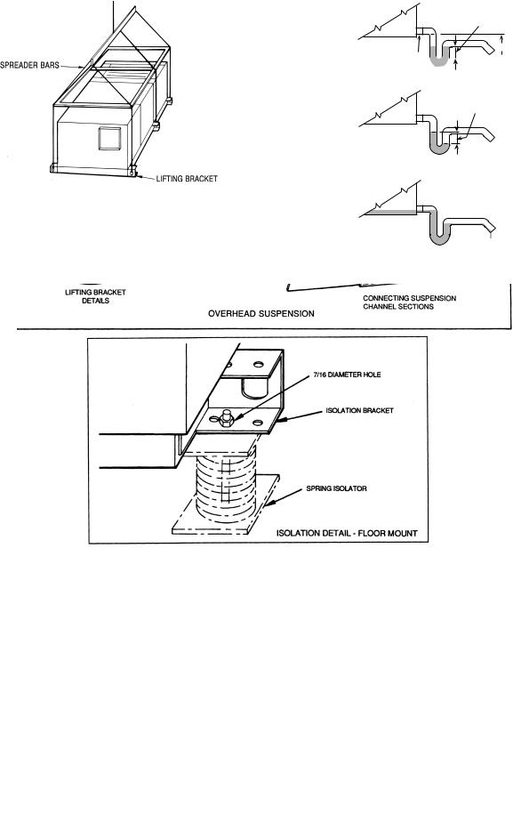
Rigging (Fig. 5) — All 39L units can be rigged by means of the lifting brackets on bottom of unit.
Units are shipped fully assembled. Do not remove shipping skids or protective covering until unit is ready for final placement. Use slings and spreader bars as applicable to lift unit. Do not lift unit by coil connections or headers.
Do not remove protective caps from coil piping connections until ready to connect piping.
Do not remove protective cover or grease from fan shaft until ready to install sheave.
Lay rigid temporary protection such as plywood walkways in unit to prevent damage to insulation or bottom panel during installation.
Suspended Units — Figure 6 shows overhead suspension of unit using optional factory-supplied suspension channels.
Each support channel consists of 2 pieces, the smaller of which fits inside the larger one. This allows the channel to be adjusted to the required length for installation.
Channels are shipped on top of the unit. The 2 sections of each channel are shipped one inside the other, and are held in place during shipping by the panel screws in the top panel.
Hardware required for installation of suspension channels is shipped in a package inside the fan section.
At least 2 suspension channels are shipped with each fan and coil unit. One or more extra channels will be supplied depending on the number of accessories ordered. Be sure to install all the suspension channels shipped with a unit. Refer to 39L Isolator Mounting (Suspended Unit) certified drawing for details.
To install suspension channels:
1.Remove panel screws to free suspension channels for installation. Replace screws in top panel.
2.Adjust channel to required length by sliding one channel section inside the other. The channel must extend at least 9 in. but not more than 12 in. beyond the edge of the unit. Set length of channel by installing factory-supplied bolts through the overlapping channel sections.
3.Mount unit to suspension channel using factory-supplied nuts and bolts through 7/16-in. diameter holes in unit lifting bracket.
4.Install field-supplied suspension rods through 9/16-in. diameter holes provided at outer edges of channel. Be sure hanger rods are securely fastened in place.
Service Clearance — Provide adequate space for unit service access (fan shaft and coil removal, filter removal, motor access, damper linkage access, etc.) as shown in Fig. 4.
Condensate Drain — To prevent excessive build-up of condensate in drain pan, adequate trap clearance must be provided beneath the unit as indicated in Fig. 7. See Installation, Condensate Drain section (page 8) for additional details.
External Vibration Isolators — Install vibration isolators per certified drawings, and in accordance with the job specifications and the instructions of the vibration isolator manufacturer. The coil piping must be isolated or have a flexible connection to avoid coil header damage because of unit motion. A flexible connection should be installed at the fan discharge.
Figure 6 shows isolation location for floor mounting or overhead suspension of unit.
4

NOTE: Dimensions in ( ) are in mm.
DIMENSIONS (ft-in.) |
DIMENSIONS (mm) |
SIZE |
A |
B |
C |
|
D |
|
E |
|
39LA |
39LB |
39LC |
||||||
|
|
|
|
|
||||
03 |
3-17/8 |
3-13/4 |
1-91/4 |
1- 711/16 |
0-77/8 |
1-33/4 |
2- 39/16 |
|
06 |
3-93/4 |
3-95/8 |
2-13/16 |
1-115/8 |
0-77/8 |
1-33/4 |
2- 39/16 |
|
08 |
4-111/16 |
4-19/16 |
2-51/8 |
2- 39/16 |
0-77/8 |
1-33/4 |
2- 39/16 |
|
10 |
4-99/16 |
4-97/16 |
2-51/8 |
2- 39/16 |
0-77/8 |
1-33/4 |
2- 39/16 |
|
12 |
5-51/16 |
5-55/16 |
2-51/8 |
2- 39/16 |
0-77/8 |
1-33/4 |
2- 39/16 |
|
15 |
5-51/16 |
5-55/16 |
3-1 |
2-119/16 |
0-77/8 |
1-33/4 |
2- 39/16 |
|
18 |
5-51/16 |
5-55/16 |
3-415/16 |
3- 33/8 |
0-77/8 |
1-33/4 |
2-117/16 |
|
21 |
6-51/4 |
6-51/8 |
3-415/16 |
3- 33/8 |
0-77/8 |
1-33/4 |
2-117/16 |
|
25 |
6-51/4 |
6-51/8 |
4-015/16 |
2- 39/16 |
0-77/8 |
1-33/4 |
2-117/16 |
SIZE |
A |
B |
C |
|
D |
|
E |
|
39LA |
39LB |
39LC |
||||||
|
|
|
|
|
||||
03 |
952 |
959 |
540 |
500 |
200 |
400 |
700 |
|
06 |
1162 |
1159 |
640 |
600 |
200 |
400 |
700 |
|
08 |
1262 |
1259 |
740 |
700 |
200 |
400 |
700 |
|
10 |
1462 |
1459 |
740 |
700 |
200 |
400 |
700 |
|
12 |
1653 |
1659 |
740 |
700 |
200 |
400 |
700 |
|
15 |
1653 |
1659 |
940 |
900 |
200 |
400 |
700 |
|
18 |
1653 |
1659 |
1040 |
1000 |
200 |
400 |
900 |
|
21 |
1962 |
1959 |
1040 |
1000 |
200 |
400 |
900 |
|
25 |
1962 |
1959 |
1240 |
700 |
200 |
400 |
900 |
Fig. 4 — Service Area Requirements
5
Table 1 — Physical Data
UNIT SIZE |
03 |
06 |
08 |
10 |
12 |
15 |
18 |
21 |
25 |
UNIT WEIGHTS (lb)* |
|
|
|
|
|
|
|
|
|
39LA |
200 |
280 |
411 |
470 |
540 |
620 |
695 |
740 |
820 |
39LB |
150 |
210 |
308 |
352 |
405 |
465 |
521 |
555 |
615 |
39LC |
170 |
238 |
349 |
400 |
459 |
527 |
590 |
629 |
697 |
39LD |
230 |
322 |
472 |
540 |
621 |
713 |
799 |
851 |
943 |
39LF |
230 |
322 |
472 |
540 |
621 |
713 |
799 |
851 |
943 |
39LG |
120 |
168 |
246 |
282 |
324 |
372 |
417 |
444 |
492 |
39LH |
220 |
308 |
452 |
517 |
594 |
682 |
764 |
814 |
902 |
COMPONENT WEIGHTS (lb) |
|
|
|
|
|
|
|
|
|
Mixing Box Section |
139 |
164 |
193 |
219 |
226 |
244 |
283 |
272 |
311 |
Filter Mixing Box |
150 |
173 |
208 |
227 |
245 |
279 |
327 |
340 |
395 |
Angle Filter Section |
75 |
82 |
97 |
107 |
114 |
134 |
140 |
159 |
185 |
Flat Filter Section |
37 |
43 |
48 |
50 |
55 |
74 |
75 |
86 |
90 |
Access Section |
48 |
55 |
60 |
64 |
68 |
74 |
77 |
87 |
92 |
Preheat (Water) Section |
36 |
42 |
43 |
46 |
49 |
52 |
54 |
53 |
57 |
Preheat (Electric) Section |
49 |
56 |
61 |
66 |
72 |
74 |
76 |
87 |
89 |
TYPICAL DRY COIL WEIGHTS (lb) |
|
|
|
|
|
|
|
|
|
Large Face Area Cooling Coils, |
|
|
|
|
|
|
|
|
|
1/2-in. OD (Chilled Water & DX)† |
56 |
84 |
98 |
109 |
137 |
178 |
198 |
251 |
280 |
4-Row |
|||||||||
6-Row |
63 |
95 |
123 |
138 |
174 |
234 |
270 |
327 |
363 |
Small Face Area Cooling Coils, |
|
|
|
|
|
|
|
|
|
1/2-in. OD (Chilled Water & DX)† |
45 |
72 |
91 |
105 |
133 |
161 |
182 |
211 |
238 |
4-Row |
|||||||||
6-Row |
53 |
85 |
113 |
129 |
162 |
197 |
225 |
270 |
307 |
8-Row |
61 |
92 |
129 |
143 |
189 |
228 |
263 |
324 |
377 |
Hot Water Coils, 1/2-in. OD† |
19 |
34 |
38 |
48 |
58 |
62 |
77 |
86 |
95 |
1-Row |
|||||||||
2-Row |
28 |
43 |
51 |
61 |
76 |
89 |
104 |
117 |
130 |
Steam Coils, 1-row, 1-in. OD |
|
|
|
|
|
|
|
|
|
6-FPI |
50 |
70 |
85 |
95 |
110 |
135 |
150 |
180 |
215 |
9-FPI |
55 |
80 |
100 |
115 |
125 |
155 |
175 |
214 |
256 |
12-FPI |
60 |
85 |
115 |
130 |
145 |
180 |
205 |
248 |
297 |
FAN |
91/2 |
125/8 |
125/8 |
|
|
181/8 |
|
|
|
Wheel Diameter (in.) |
15 |
15 |
20 |
20 |
25 |
||||
Wheel Width (in.) |
71/8 |
91/2 |
111/8 |
111/8 |
15 |
15 |
131/2 |
18 |
15 |
Shaft Diameter (in.) |
3/4 |
13/16 |
13/16 |
13/16 |
13/16 |
17/16 |
17/16 |
17/16 |
111/16 |
Maximum Fan Rpm |
2500 |
2000 |
2000 |
1600 |
1600 |
1400 |
1300 |
1100 |
1000 |
OPERATING CHARGE, R-22 (lb) |
|
|
|
|
|
|
|
|
|
4-Row Coil |
1-2 |
2-3 |
3-4 |
4-5 |
4-5 |
5- 6 |
6- 7 |
6- 8 |
6- 9 |
6-Row Coil |
1-2 |
2-4 |
5-6 |
5-6 |
6-8 |
8-10 |
9-11 |
11-13 |
11-16 |
8-Row Coil |
2-3 |
3-5 |
5-6 |
5-7 |
7-9 |
10-12 |
12-14 |
13-19 |
16-24 |
COIL VOLUME (gal. water) |
|
|
|
|
|
|
|
|
|
Chilled Water, 1/2-in. OD Tube, |
|
|
|
|
|
|
|
|
|
Large Face Area |
|
|
|
|
|
|
|
|
|
4-Row |
2.5 |
3.5 |
4.5 |
5.2 |
5.6 |
7.3 |
8.5 |
10.4 |
12.0 |
6-Row |
3.2 |
4.7 |
6.0 |
6.8 |
7.7 |
10.1 |
11.7 |
14.2 |
16.3 |
Chilled Water, 1/2-in. OD Tube, |
|
|
|
|
|
|
|
|
|
Small Face Area |
|
|
|
|
|
|
|
|
|
4-Row |
2.1 |
3.3 |
3.9 |
4.1 |
5.1 |
6.3 |
7.3 |
8.7 |
9.8 |
6-Row |
2.4 |
3.7 |
5.1 |
5.9 |
6.6 |
8.3 |
9.5 |
11.8 |
13.5 |
8-Row |
2.7 |
4.1 |
6.4 |
7.4 |
8.4 |
10.7 |
12.1 |
14.7 |
17.2 |
Hot Water, 1/2-in. OD Tube |
0.5 |
0.8 |
1.0 |
1.3 |
1.5 |
1.8 |
2.1 |
2.5 |
2.9 |
1-Row |
|||||||||
2-Row |
0.7 |
1.3 |
1.6 |
2.0 |
2.4 |
2.9 |
3.4 |
4.0 |
4.8 |
COOLING COILS |
|
|
|
|
|
|
|
|
|
Chilled Water 1/2-in. OD Tube, |
|
|
|
|
|
|
|
|
|
(4, 6 Row) Large Face Area |
|
|
|
|
|
|
|
|
|
Face Area (sq ft) |
3.63 |
5.90 |
7.90 |
9.54 |
11.18 |
14.91 |
17.71 |
21.6 |
25.0 |
Number of Tubes/Face |
16 |
20 |
24 |
24 |
24 |
32 |
38 |
38 |
44 |
Finned Tube Length (in.) |
26.1 |
34.0 |
37.9 |
45.8 |
53.7 |
53.7 |
53.7 |
65.5 |
65.5 |
Chilled Water 1/2-in. OD Tube |
|
|
|
|
|
|
|
|
|
(4, 6, 8 Row) Small Face Area |
|
|
|
|
|
|
|
|
|
Face Area (sq ft) |
2.72 |
4.72 |
6.58 |
7.95 |
9.32 |
12.12 |
13.98 |
17.1 |
20.5 |
Number of Tubes/Face |
12 |
16 |
20 |
20 |
20 |
26 |
30 |
30 |
36 |
Finned Tube Length (in.) |
26.1 |
34.0 |
37.9 |
45.8 |
53.7 |
53.7 |
53.7 |
65.5 |
65.5 |
DX 1/2-in. OD Tube |
|
|
|
|
|
|
|
|
|
(4, 6 Row) Large Face Area |
|
|
|
|
|
|
|
|
|
Face Area (sq ft) |
3.63 |
5.90 |
7.90 |
9.54 |
11.18 |
14.91 |
17.71 |
21.6 |
25.0 |
Finned Tube Length (in.) |
26.1 |
34.0 |
37.9 |
45.8 |
53.7 |
53.7 |
53.7 |
65.5 |
65.5 |
DX 1/2-in. OD Tube |
|
|
|
|
|
|
|
|
|
(4, 6, 8 Row) Small Face Area |
|
|
|
|
|
|
|
|
|
Face Area (sq ft) |
2.72 |
4.72 |
6.58 |
7.95 |
9.32 |
12.12 |
13.98 |
17.1 |
20.5 |
Finned Tube Length (in.) |
26.1 |
34.0 |
37.9 |
45.8 |
53.7 |
53.7 |
53.7 |
65.5 |
65.5 |
HEATING COILS |
|
|
|
|
|
|
|
|
|
Hot Water 1/2-in. OD Tube, |
|
|
|
|
|
|
|
|
|
U-Bend (1, 2 Row) |
|
|
|
|
|
|
|
|
|
Face Area (sq ft) |
2.72 |
4.72 |
6.58 |
7.95 |
9.32 |
12.12 |
13.98 |
17.1 |
20.5 |
Number Tubes/Face |
12 |
16 |
20 |
20 |
20 |
26 |
30 |
30 |
36 |
Finned Tube Length (in.) |
26.1 |
34.0 |
37.9 |
45.8 |
53.7 |
53.7 |
53.7 |
65.5 |
65.5 |
Steam 1-in. OD (1 Row) |
|
|
|
|
|
|
|
|
|
Face Area (sq ft) |
2.13 |
4.18 |
6.22 |
7.53 |
8.85 |
11.06 |
13.28 |
16.2 |
18.9 |
Number Tubes/Face |
4 |
6 |
8 |
8 |
8 |
10 |
12 |
12 |
14 |
Finned Tube Length (in.) |
25.5 |
33.4 |
37.3 |
45.2 |
53.1 |
53.1 |
53.1 |
53.1 |
64.9 |
LEGEND |
*Less coil. |
DX — Direct Expansion |
†Coils have 14 aluminum fins per inch on copper tubes. |
|
|
FPI — Fins Per Inch |
|
6
NOTE: Lift in one piece. Use slings and spreader bars at each lifting bracket.
Fig. 5 — Unit Rigging Details
DIFFERENTIAL 1
H
DRAIN NIPPLE


FAN OFF
DIFFERENTIAL 2
TRAP CONDITION WHEN FAN STARTS
COOLING COIL
DRAIN PAN
FAN RUNNING AND CONDENSATE DRAINING
Fig. 7 — Condensate Drain
Fig. 6 — Unit Support Details
7
INSTALLATION
Mixing Box
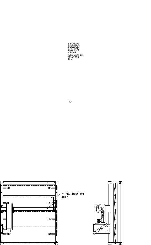
DAMPER ACTUATORS — The 39L mixing boxes are supplied with low leak dampers and blade and edge seals. Damper operating torques are shown in Table 2.
The actuator and mounting brackets are field supplied and may be mounted inside or outside the unit. A typical inside mounting bracket is shown in Fig. 8. For external mounting of actuators, drill or punch a hole in the exterior panel.
NOTE: If the unit is shipped with AirManager™ controls, actuator(s) are factory-supplied. Refer to Table. 3.
To ensure torque is transmitted equally to both damper sections, actuator must be connected to the 1-in. hollow jackshaft that drives the interconnecting linkage bar. Connection to any other shaft is not recommended.
DUCTWORK ATTACHMENT — Ductwork should be flanged out and attached to the mixing box panels as shown in Fig. 9. See Fig. 10 for duct connection sizes.
Table 2 — Mixing Box Damper Operating Torque
(in.-lb)
39L UNIT SIZE |
TORQUE |
03 |
20 |
06 |
20 |
08 |
26 |
10 |
29 |
12 |
33 |
15 |
41 |
18 |
52 |
21 |
56 |
25 |
76 |
NOTES:
1.Torque values are based on interconnected dampers driven by one operator. For units with separate operators for each damper, calculate torque as follows: Table values x .80 = torque per damper section.
2.Damper shaft moves 90 degrees from open to closed position.
Condensate Drain — Install a trapped condensate drain line at unit drain connection. Use 1-in. standard pipe.
Measure maximum design negative static pressure upstream from the fan. Referring to Fig. 7, height “H” must be equal to or larger than negative static pressure at design operating conditions. Prime enough water in trap to prevent losing seal (Differential 1). When the fan starts, Differential 2 is equal to the maximum negative static pressure.
Provide freeze-up protection as required.
MXB — Mixing Box
Fig. 9 — Mixing Box Ductwork Attachment
Fig. 8 — Typical Mixing Box Actuator Mounting
8
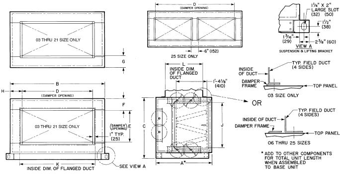
Table 3 — Recommended Actuators
|
|
|
|
ROUND |
|
DAMPER AREA |
|
MAXIMUM |
MAXIMUM |
|
ACCESSORY |
|
|
|
SHAFT |
|
(sq ft) |
|
|||
ACTUATOR |
VOLTAGE |
|
TIMING |
TORQUE |
WIRE |
|||||
PACKAGE |
VA |
SIZE |
|
|
STROKE |
|||||
PART NO. |
(50/60 Hz) |
(sec) |
Parallel |
Opposed |
(in.-lb) |
LENGTH |
||||
NO. |
|
|
|
MIN-MAX |
|
|
(degrees) |
(ft) |
||
|
|
|
|
(in.) |
|
|
|
|
|
|
|
|
|
|
|
|
|
|
|
|
|
33AMACTDMP133 |
HF27BJ035* |
24 |
10 |
.750-1.050 |
150 |
44 |
53 |
133 |
90 |
300 |
33AMACTGV-133 |
HF27BJ033 |
24 |
4 |
.375- .625 |
< 150 |
N/A |
N/A |
133 |
90 |
725 |
33AMACTGV-266 |
HF27BJ034 |
24 |
6 |
.475- .750 |
135 |
N/A |
N/A |
266 |
90 |
450 |
*Actuator is spring-return type. NOTES:
1.All actuators are direct coupled type, designed to be directly mounted into jackshaft assembly.
2.All actuators are equipped with a plenum rated cable, factoryterminated to the actuator. Part No. HF27BB035 and 034 are 16 ft, HF27BB033 is 9.5 ft.
3.Damper areas are nominal and based on low leakage type dampers.
4.For larger damper assemblies, multiple activators may be used.
5.Part No. HF27BB033 and 034 are designed for inlet guide vane and face and bypass applications, but may be used for external relief dampers if spring return is not required.
NOTES:
1.Hand is determined by the location of the fan drive and/or coil connection when viewed while facing the direction toward which air is flowing.
2.Dimensions in ( ) are in millimeters.
DIMENSIONS (ft-in.)
UNIT |
A |
B |
C |
D |
E |
F |
G |
H |
J |
K |
L |
|
39L- |
||||||||||||
|
|
|
|
|
|
|
|
|
|
|
||
03 |
2- 39/16 |
3-17/8 |
2-01/4 |
1- 5 |
1-5 |
0- 15/8 |
0-61/16 |
0-101/2 |
1-43/4 |
1-51/4 |
1- 51/4 |
|
06 |
2- 39/16 |
3-93/4 |
2-43/16 |
1-11 |
1-5 |
0- 41/8 |
0-61/16 |
0-113/8 |
1-811/16 |
2-11/4 |
1- 71/4 |
|
08 |
2- 39/16 |
4-111/16 |
2-81/8 |
3- 1 |
1-5 |
0- 61/16 |
0-61/16 |
0- 63/8 |
2-05/8 |
3-31/4 |
1- 71/4 |
|
10 |
2- 39/16 |
4-99/16 |
2-81/8 |
3- 5 |
1-5 |
0- 61/16 |
0-61/16 |
0- 85/16 |
2-05/8 |
3-71/4 |
1- 71/4 |
|
12 |
2- 39/16 |
5-57/16 |
2-81/8 |
3-11 |
1-5 |
0- 61/16 |
0-61/16 |
0- 91/4 |
2-05/8 |
4-11/4 |
1- 71/4 |
|
15 |
2- 39/16 |
5-57/16 |
3-4 |
3-11 |
1-9 |
0- 8 |
0-41/16 |
0- 91/4 |
2-81/2 |
4-11/4 |
1-111/4 |
|
18 |
2-117/16 |
5-57/16 |
3-715/16 |
3-11 |
2-3 |
0- 7 |
0-5 |
0- 91/4 |
3-07/16 |
4-11/4 |
2- 51/4 |
|
21 |
2-117/16 |
6-51/4 |
3-715/16 |
3-11 |
2-5 |
0- 6 |
0-4 |
1- 31/8 |
3-07/16 |
4-11/4 |
2- 71/4 |
|
25 |
2-117/16 |
6-51/4 |
4-313/16 |
5- 4 |
2-5 |
0- 97/8 |
0-4 |
0- 65/8 |
3-85/16 |
5-61/4 |
2- 71/4 |
Fig. 10 — Mixing Box Duct Connections
9
Inlet Guide Vane (IGV) Actuators — The control board positions the unit IGVs in order to maintain the duct static pressure, as measured by the static pressure transducer, at the required set point. The IGV actuator is electrically connected to the control board and receives a signal whenever the guide vane position needs to be adjusted. The guide vane actuator is mounted to the IGV jackshaft, and secured to the jackshaft mounting member in order to prevent rotation.
For factory-installed controls which are ordered with the unit, the IGV actuator is properly sized and factory mounted to the IGV jackshaft. The actuator wiring is routed across the fan section to a junction box which is mounted to the exterior of the unit. Two compatible actuators are available for field installation. Both actuators are supplied with a length of plenum rated cable to facilitate installation inside the unit. See Table 3 for actuator specifications and typical applications.
Jackshaft and IGV linkage setup adjustments are extremely important for proper IGV performance and static pressure control. Closely follow all instructions.
To install the IGV actuators, perform the following:
1.Disconnect power to the fan motor prior to performing the installation.
2.Open the fan access door and locate the IGV jackshaft. Measure the IGV jackshaft diameter. Verify that the size is within the range of the actuator chosen. See Table 3.
3.Loosen the U-bolt locking nuts on the actuator.
4.Slip the actuator over the IGV jackshaft. Align the actuator parallel with the frame member which supports the jackshaft.
5.Take the anti-rotation bracket supplied with the actuator and, with the center locking pin pointed outward, slip the pin into the slot at the far end of the actuator. Seat the pin into the center of the groove provided. If the anti-rotation bracket is not seated against the frame member, measure the distance from the member and remove the antirotation bracket from the actuator. Bend the bracket to the required offset. See Fig. 11.
6.With the anti-rotation bracket installed in the actuator groove, locate the hole in the bracket, closest to the pin, which is fully in contact against the frame. Mark this hole location on the frame. Trace the outline of the bracket on the frame so that it can be re-aligned again when removed.
7.Remove the bracket and actuator. Drill a pilot hole at the location marked from Step 6. Install one screw through the hole. Re-align the bracket with the outline made previously and tighten the screw.
8.Locate and mark the hole on the opposite end of the bracket, closest to the pin, which contacts the frame. Drill a pilot hole in this location and install the remaining screw. Remove the first screw.
9.Install the actuator on the jackshaft and while moving into position, adjust the free end of the anti-rotation bracket so that the pin fully locks into the slot provided in the actuator. Once the actuator is adjusted into position, install the remaining screw into the anti-rotation bracket. See Fig. 12.
10.Rotate the jackshaft to fully close the IGVs. Press the release button (BLACK) on the face of the actuator, and rotate the clamp in the same direction that closed the IGVs, until the actuator stop is reached. With the release still pressed, rotate the actuator clamp from the full closed position to the .1 mark and release the actuator release button. Lock the U-bolt clamp into position to secure the actuator to the IGV jackshaft.
11.If a second actuator is required, repeat the process for a second actuator. The second actuator mounts on the opposite side of the fan on the opposite end of the jackshaft.
ACTUATOR WIRING — To wire the actuator, perform the following:
1.Each actuator is supplied with a length of plenum rated cable. Route the cable from the actuator to the exterior of the unit. Allow a sufficient service loop to provide free movement of the fan sled.
2.At the desired location for field connection, drill a 3/8-in. hole (two holes within a 7/8-in. diameter are required if two actuators are used) through the unit and route the cable through the hole.
3.Install a field-supplied bushing to protect the cable and seal the hole, using a suitable silicone sealer such as Form-A-Gasket® by Permatex to secure the cable and prevent air leakage.
4.Remove the center back plug from a field supplied 2 x 4-in. electrical junction box. Route the cable(s) through the hole and secure the box to the unit using 2 fieldsupplied no. 10 drill/tap screws.
5.Use a 3 or 4-conductor, 18 AWG cable or individual 18 AWG wiring using RED, WHITE, and BLACK color coding to connect the actuator to the control box.
6.Inside the control box, connect all RED wire(s) together. Secure with wire nuts or closed end crimp type connectors.
7.Inside the control box, connect all BLACK wire(s) together. Secure with wire nuts or closed end crimp type connectors.
8.Inside the control box, connect all WHITE wire(s) together. Secure with wire nuts or closed end crimp type connectors.
9.At the control box, strip 1/4-in. of insulation from each conductor. Equip each conductor with a 1/4-in. female spade type crimp connector.
10.Connect the RED wire to terminal T37 on the control board.
11.Connect the WHITE wire to terminal T39 on the control board.
12.Connect the BLACK wire to terminal no. 3 on the TB2 terminal block in the control box.
13.Check the rotation of the actuator. The switch is factory set in the A position which provides clockwise rotation to open the IGVs. If counterclockwise rotation is required to open the IGVs, reset the actuator switch to the B position.
To adjust the jackshaft linkage, perform the following:
1.Refer to Fig. 12. Close the IGVs fully.
2.Loosen the crankarm and rods. Press the release button on the actuator and rotate it to the .9 mark for right hand units or the .1 mark for left hand units. Rotate the crankarm on the jackshaft to a position which is about 30 degrees from parallel alignment with the rod connecting the IGV.
3.Tighten the crankarm into this position.
4.Close the IGVs fully by hand. Tighten the rod into position.
5.Test the actuator and IGV operation. Be sure the IGVs fully close and open. Re-adjust the position of the swivel joint outward if full IGV travel is not reached with the actuator 90 degree rotation. If the IGVs reach the end of full travel in less than 90 degrees of actuator rotation, adjust the swivel joint inward toward the jackshaft. After making any adjustment, repeat Steps 2-5.
10
JACKSHAFT |
|
|
|
|
|
|
|
|
|
|
|
|
|
|
|
|
|
CRANKARM |
ANTIROTATION STRAP |
|||||
|
|
|
|
|
|
|
|
|
|
|
|
|
|
|
|
|
|
|
|
|
|
|
|
INSTALLED (ACTUATOR |
|
|
|
|
|
|
|
|
|
|
|
|
|
|
|
|
|
|
|
|
|
|
|
|
NOT SHOWN FOR |
|
|
|
|
|
|
|
|
|
|
|
|
|
|
|
|
|
|
|
|
|
|
|
|
CLARITY) |
|
|
|
|
|
|
|
|
|
|
|
|
|
|
|
|
|
|
|
|
|
|
|
|
|
|
|
|
|
|
|
|
|
|
|
|
|
|
|
|
|
|
|
|
|
|
|
|
|
|
|
|
|
|
|
|
|
|
|
|
|
|
|
|
|
|
|
|
|
|
|
|
|
|
|
|
|
|
|
|
|
|
|
|
|
|
|
|
|
|
|
|
|
|
|
|
|
|
|
|
|
|
|
|
|
|
|
|
|
|
|
|
|
|
|
|
|
|
|
|
|
|
|
|
|
|
|
|
|
|
|
|
|
|
|
|
|
|
|
|
|
|
|
|
|
|
|
|
|
|
|
|
|
|
|
|
|
|
|
|
|
|
|
|
|
|
|
|
|
|
|
|
|
|
|
Fig. 11 — IGV Actuator Bracket Installation
IGV ACTUATOR |
CONNECTING ROD |
|
ANTIROTATION |
IGV |
STRAP |
JACKSHAFT |
|
|
INLET GUIDE |
|
VANES (IGV) |
Fig. 12 — IGV Actuator Mounting
Install Fan Motor — For field installation of motors, be sure electrical junction box is toward the center of the unit.
This is necessary for drive and belts to be properly tightened. Use smallest slots in motor mounting base that will accommodate motor and allow minimum overhang (Fig. 13). Be sure that motor holddown bolts are tight on field-installed motor.
JUNCTION BOX CONDENSATE PREVENTION — When air handlers are installed outdoors in a high humidity environment or indoors where the apparatus room is used as a fresh air plenum, precautions must be taken to prevent condensation from forming inside the junction box of the internally mounted motor.
Standard installation practice is to mount the motor starter or fused disconnect box adjacent to the air handler and enclose the power wiring to the motor in flexible conduit.
The sheet metal housing of the disconnect switch or motor starter is not airtight (even when a box meeting NEMA [National Electrical Manufacturers Association] IV standards is used). Thus, warm moist air can migrate through the flexible conduit to the junction box on the motor. With the motor located inside the unit, the motor temperature is that of the cool
supply air; thus, condensate can form inside the junction box and, possibly, on the live terminal lugs.
To prevent the moist air from migrating through the conduit to the motor, seal the power wires inside the flexible conduit at the motor starter or fused disconnect.
Use a nonconductive, nonhardening sealant. Permagum (manufactured by Schnee Morehead) or sealing compound, thumb grade (manufactured by Calgon), are acceptable materials.
POWER KNOCKOUTS — Panels are not provided with knockouts for the fan motor power wiring. Openings must be drilled or punched in the exterior panels of the unit. It is recommended that power wiring be routed through the discharge panel whenever possible, as this panel is rarely removed for service access.
Install Sheaves on Motor and Fan Shafts —
Factory-supplied drives are prealigned and tensioned, however, Carrier recommends that you check the belt tension and alignment before starting the unit. Always check the drive alignment after adjusting belt tension.
11
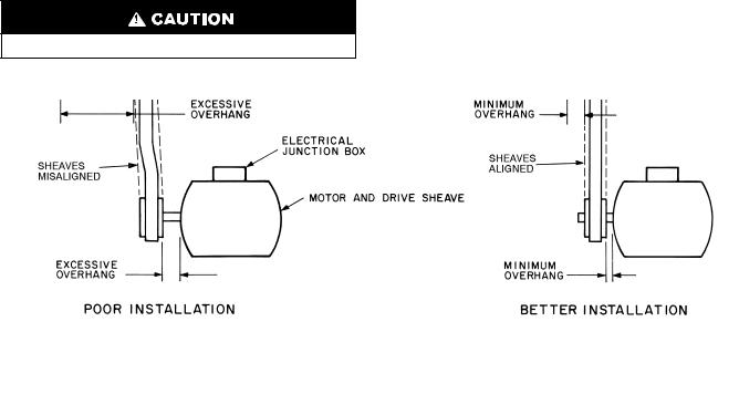
When field installing or replacing sheaves, install sheaves on fan shaft and motor shaft for minimum overhang. (See Fig. 13.) Use care when mounting sheave on fan shaft; too much force may damage bearing. Remove rust-preventative coating or oil from shaft. Make sure shaft is clean and free of burrs. Add grease or lubricant to bore of sheave before installing.
The 39L fan, shaft, and drive pulley are balanced as a complete assembly to a high degree of accuracy. If excessive unit vibration is present after fan pulley replacement, the unit must be rebalanced. For drive ratio changes, always reselect the motor pulley — do not change the fan pulley.
ALIGNMENT — Make sure that fan shafts and motor shafts are parallel and level. The most common causes of misalignment are nonparallel shafts and improperly located sheaves. Where shafts are not parallel, belts on one side are drawn tighter and pull more than their share of the load. As a result, these belts wear out faster, requiring the entire set to be replaced before it has given maximum service. If misalignment is in the sheave, belts will enter and leave the grooves at an angle, causing excessive belt cover and sheave wear.
1.Shaft alignment can be checked by measuring the distance between the shafts at 3 or more locations. If the distances are equal, then the shafts will be parallel.
2.Sheave alignment:
Fixed sheaves — To check the location of the fixed sheaves on the shafts, a straightedge or a piece of string can be used. If the sheaves are properly lined up the string will touch them at the points indicated by the arrows in Fig. 14.
Adjustable sheave — To check the location of adjustable sheave on shaft, make sure that the centerlines of both sheaves are in line and parallel with the bearing support channel. See Fig. 14. Adjustable pitch drives are installed on the motor shaft.
With adjustable sheave, do not exceed maximum fan rpm.
3.Rotating each sheave a half revolution will determine whether the sheave is wobbly or the drive shaft is bent. Correct any misalignment.
4.With sheaves aligned, tighten cap screws evenly and progressively.
NOTE: There should be a 1/8-in. to 1/4-in. gap between the mating part hub and the bushing flange. If gap is closed, the bushing is probably the wrong size.
5.With taper-lock bushed hubs, be sure the bushing bolts are tightened evenly to prevent side-to-side pulley wobble. Check by rotating sheaves and rechecking sheave alignment. When substituting field-supplied sheaves for factory-supplied sheaves, consider that the fan shaft sheave has been factory balanced with fan and shaft as an assembly. For this reason, substitution of motor sheave is prefer-able for final speed adjustment.
Install V-Belts — When installing or replacing belts, always use a complete set of new belts. Mixing old and new belts will result in the premature wear or breakage of the newer belts.
1.Always adjust the motor position so that V-belts can be installed without stretching over grooves. Forcing belts can result in uneven stretching and a mismatched set of belts.
2.Do not allow belt to bottom out in sheave.
3.Tighten belts by turning motor-adjusting jackscrews. Turn each jackscrew an equal number of turns.
4.Equalize belt slack so that it is on the same side of belt for all belts. Failure to do so may result in uneven belt stretching.
5.Tension new drives at the maximum deflection force recommended (Fig. 15).
Fig. 13 — Determining Sheave-Shaft Overhang
12
 Loading...