


39L

With Product Integrated Controls (PIC)
Installation, Operation, and
Start-Up Instructions
CONTENTS
Page
SAFETY CONSIDERATIONS ...................2
GENERAL ...................................2
INSTALLATION .............................2-64
Service Area Requirements ...................2
Remote Control Box Option ..................2
• REMOTE CONTROL BOX CONDENSATE
PREVENTION
Make Electrical Connections ..................3
Variable Frequency Drives ...................38
Water Valve Assemblies .....................38
• VALVE WIRING
Duct Static Pressure Probe (VAV Units) ......39
Space Temperature Sensor ..................40
Outdoor-Air Temperature Sensor .............42
Mixed-Air Temperature Sensor ...............42
Enthalpy Switch ............................43
• CONTROL RANGES
Supply-Air Temperature Sensor ..............44
Return-Air Temperature Sensor ..............44
Heat Interlock Relay .........................45
Fan Relay ..................................45
Duct High Humidity Switch ..................45
Wall-Mounted Relative Humidity Sensor ......46
Duct-Mounted Relative Humidity Sensor ......47
• LOCATION FOR OUTSIDE AIR RELATIVE
HUMIDITY
• LOCATION FOR RETURN AIR RELATIVE
HUMIDITY
Mixing Box Linkage .........................47
Airflow Switch ..............................48
Low-Temperature Thermostat ................48
Outdoor-Air Thermostat .....................48
Filter Status Switch .........................49
High-Pressure Switch .......................49
Air Quality Sensors .........................49
Constant Outside Air (OAC) Control ..........50
• PROBE INSTALLATION
• OAC CALIBRATION
• USING OAVP VALUES TO DETERMINE DUCT
AIRFLOW
• FIELD-SUPPLIED OR HIGH-VELOCITY
PRESSURE TRANSDUCERS
Field Wiring Connections ....................52
• REMOTE LOCAL INTERFACE DEVICE (HSIO)
• RETURN-AIR TEMPERATURE SENSOR,
OUTDOOR-AIR TEMPERATURE SENSOR,
ENTHALPY SWITCH, AND MIXED-AIR
TEMPERATURE SENSOR
• SPACE TEMPERATURE SENSOR (SPT)
• DAMPER ACTUATORS
• SMOKE CONTROL OPTION
• ANALOG DEVICE FOR ANALOG OUTPUT
TEMPERATURE CONTROL
39L,NX
Central Station Air-Handling Units
• DEVICE UNDER DISCRETE OUTPUT
TEMPERATURE CONTROL
• DISCRETE OUTPUT DEVICE UNDER
TIMECLOCK CONTROL
• HUMIDIFICATION DEVICES
• AIR QUALITY SENSOR
• OUTSIDE AIR VELOCITY PRESSURE (OAVP)
SENSOR
• FAN VOLUME CONTROL
• ELECTRIC HEATER
• CARRIER COMFORT NETWORK INTERFACE
• OUTDOOR-AIR THERMOSTAT
CONTROL SYSTEM .......................64-68
Processor (PSIO Master) and Option (PSIO Slave)
Modules .................................65
Relay (DSIO) Module .......................65
Local Interface Device (HSIO) ...............67
CONTROL OPERATION ...................69-91
Accessing Functions and Subfunctions .....69
Display Functions ..........................69
• SUMMARY DISPLAY
• STATUS FUNCTION
• HISTORY FUNCTION
• TEST FUNCTION
Programming Functions ...................81
• SERVICE FUNCTION
• SET POINT FUNCTION
• SCHEDULE FUNCTION
CONTROL OPERATING SEQUENCE .......92-102
Constant Volume and Variable Air
Volume Units ............................92
Constant Volume Units Only ................96
Variable Air Volume Units Only .............99
START-UP ..............................103-108
Initial Check ..............................103
Quick Test ................................103
Electronic Valve Actuator Field Test ........108
CONTROL LOOP CHECKOUT ............108,109
To Check Operation of Analog Outputs .....108
VALVE TROUBLESHOOTING .............109-111
General ...................................109
1
⁄2-in. Through 11⁄4-in. Electric Hot Water/Steam
All
Valve Assemblies .......................109
All 11⁄2-in. Through 3-in. Valve Assemblies ..110
CONTROL MODULE
TROUBLESHOOTING ..................111,112
General ...................................111
Module Replacement (PSIO, DSIO) .........112
UNIT TROUBLESHOOTING ...............113-115
METRIC CONVERSION CHART .............116
Manufacturer reserves the right to discontinue, or change at any time, specifications or designs without notice and without incurring obligations.
Book 3
Tab 1b
PC 201 Catalog No. 533-913 Printed in U.S.A. Form 39L,NX-2SI Pg 1 3-96 Replaces: 39L,NX-1SI
IMPORTANT: This equipment generates, uses, and can
radiate radio frequency energy and if not installed and
used in accordance with these instructions may cause
radio interference. It has been tested and found to comply with the limits of a Class A computing device as
defined by FCC regulations, Subpart J of Part 15, which
are designed to provide reasonable protection against
such interference when operated in a commercial
environment.
SAFETY CONSIDERATIONS
Installation and start-up of air-conditioning equipment can
be hazardous due to system pressure and electrical components. Only trained and qualified service personnel should
install, start up, or service air-conditioning equipment.
When working on air-conditioning equipment, observe precautions in the literature, tags and labels attached to the unit,
and other safety precautions that may apply.
Follow all safety codes, including ANSI (American
National Standards Institute) Z223.1 (latest version). Wear
safety glasses and work gloves.
Disconnect all power to the unit before performing maintenance or service. Unit may automatically start if power
is not disconnected. Electrical shock and personal injury could result.
Do not store or use gasoline or other flammable vapors
and liquids in the vicinity of this or any other
appliance.
GENERAL
The Product Integrated Control (PIC) option is available
for 39L and 39NX indoor units with a draw-thru configuration. The PIC control box can be supplied as part of a dedicated PIC section; it is factory-installed and wired and has
the same hand (orientation) as the fan section. The control
box can also be shipped separately for remote mounting without a PIC section. For the remote control box option, all connections from the control box to the unit are made to a junction box in the unit’s fan section.
The control box includes electronic modules, fuses, relays, transformers, terminal blocks, low-limit air temperature protection (optional), static pressure transducer (VAV
[Variable Air Volume] units only) and high-pressure switch
(VAV units). An ON/OFF switch is included to shut off the
power to the control box.
PIC environmental limitations are as follows:
Shipping Temperature — −20 to 165 F
Shipping Humidity — 10 to 95%
Operating Temperature — 32 to 125 F
Operating Humidity — 30 to 90%
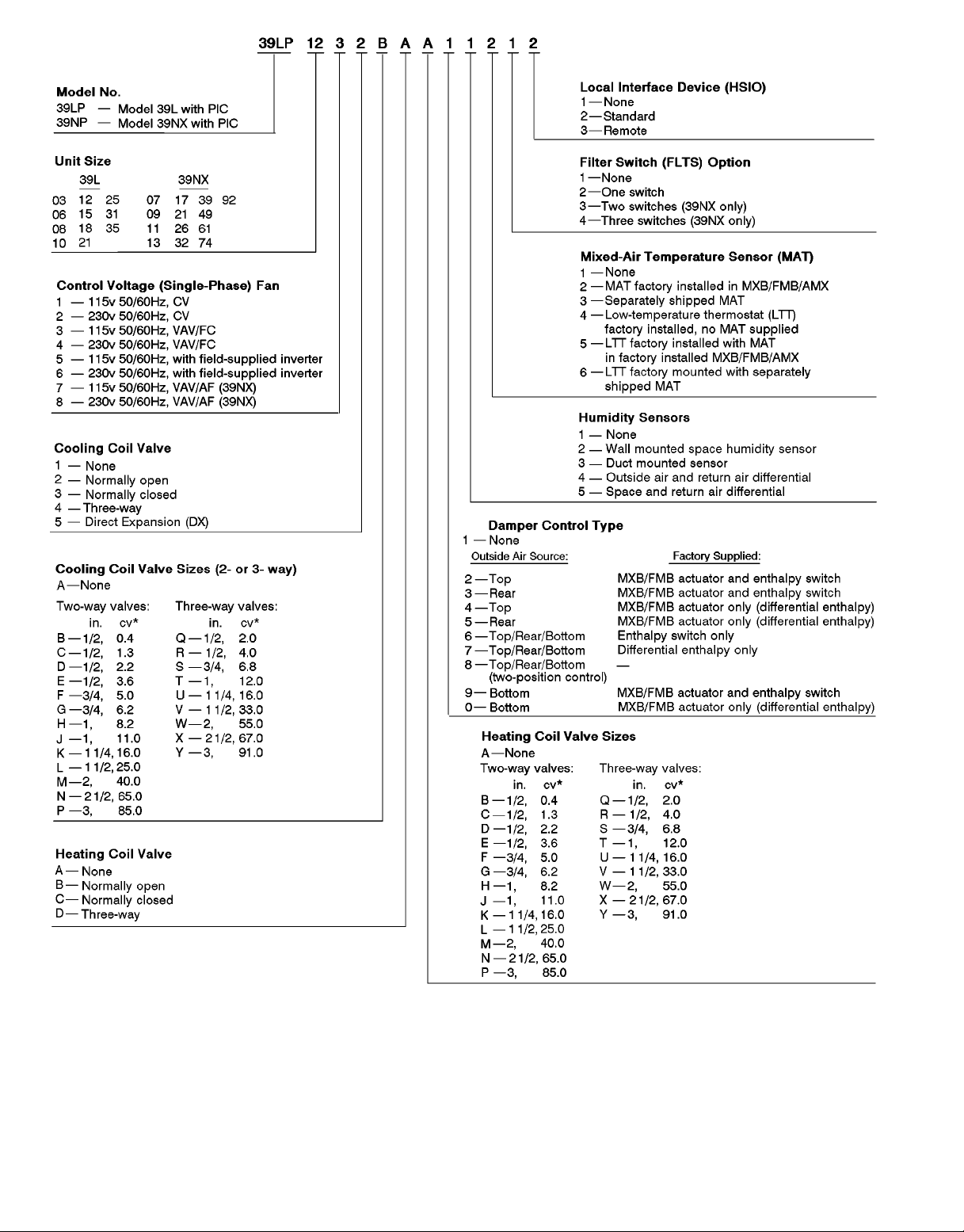
INSTALLATION
Follow all basic installation instructions for 39L or 39NX
units as described in the 39L or 39NX Installation, Start-Up,
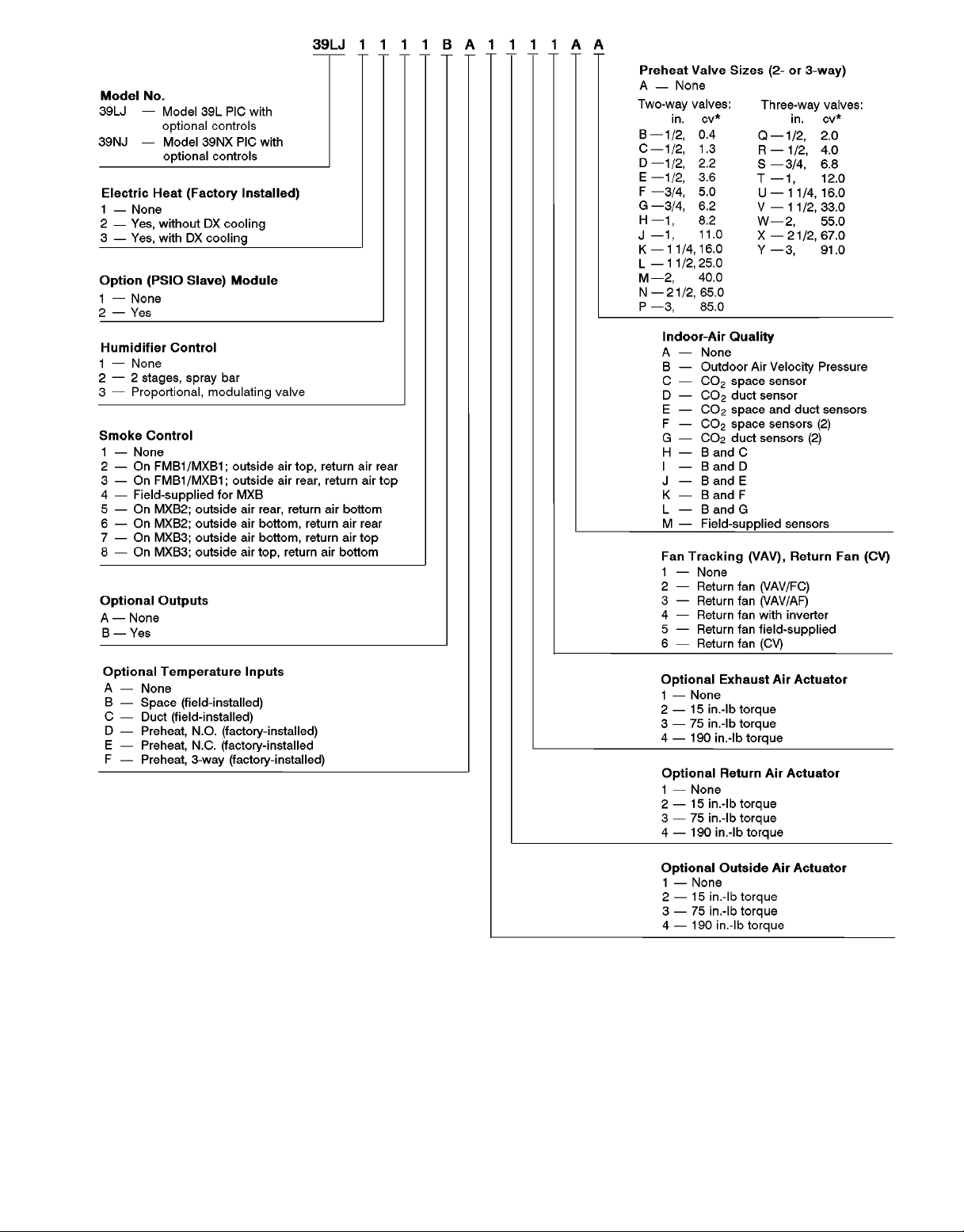
and Service Instructions shipped with the unit. To verify the
PIC and PIC option configurations according to the model
numbers, see Fig. 1 and 2.
Leave protective coverings on the unit until it is installed
inside and protected from the elements, construction debris,
and dirt.
Use one of the keys provided in the 39L or 39NX installation packet (located in fan section) to open the control box
door.Visually inspect all components and wiring for any damage. Remove the valve assembly packages and the sensor
packages from the fan section. For units with PIC sections,
remove protective plastic caps from the bulkhead fittings
(located on the top edge of the control box) and discard.
Verify that the 10.0 amp ON/OFF switch located on the
PIC control box door is in the OFF position. Do not turn the
power supply on at this time.
NOTE: The 39NX and 39L air handlers are designed for indoor applications. Modified units are available for outdoor
applications on pier or slab mounts (not curb mounts). Prod-
uct integrated controls are not available for outdoor applications. Consult your Carrier sales representative for further
details.
ServiceArea Requirements — Article 110-16 of the
NEC (National Electrical Code) describes electrical installation.All 39L and 39NX PIC installations must comply with
the minimum clearances required for electrical installation
as listed in Table 110-16(a) of the code. Make sure to provide the necessary clearance from the PIC unit to any adjoining wall. Refer to the base unit installation instructions
for detailed dimensions for each unit section.
Remote Control Box Option — This option allows
the PIC control box to be mounted away from the unit; the
remote control box (Fig. 3) must be wired to the supply fan
section. Mount the remote control box assembly to the
mechanical room wall near the unit using field-supplied
Unistrutt metal framing or equivalent supports. The control
box has 4 mounting holes in the back of the enclosure for
this purpose.
2
Mount the remote control box as follows:
1. Loosen and remove the 4 nuts securing the control panel
in the control box.
2. Remove the control panel from the box; set the panel and
nuts aside for reassembly later.
3. Mount the control box to the Unistrutt support using fieldsupplied fasteners.
4. Locate, mark, and drill pilot holes on the top of the box
for each of the following:
• Motor starter wiring
• Actuator and sensor wires to fan section junction box
• Supply power wires (ac)
• Valve wiring or tubing (water valves, field-supplied
sensors, or other devices)
5. Expand the pilot holes as required. Recommended sizes
are as follows:
• Motor starter wiring —3⁄4in. (5 wires)
• Actuator and sensor wires to fan section junction
box —
3
⁄4in. to 1 in. (number of wires and hole di-
ameter determined by application)
1
• Supply power wires (ac) —
⁄2in. or3⁄4in.
• Valve wiring or tubing — size as required
Fan section panels are provided with pilot holes that can
be drilled or punched to accomodate an electrical conduit
for the remote control box wiring. Where possible, install
the conduit in a panel that will not be removed, such as the
discharge panel. See Fig. 4.
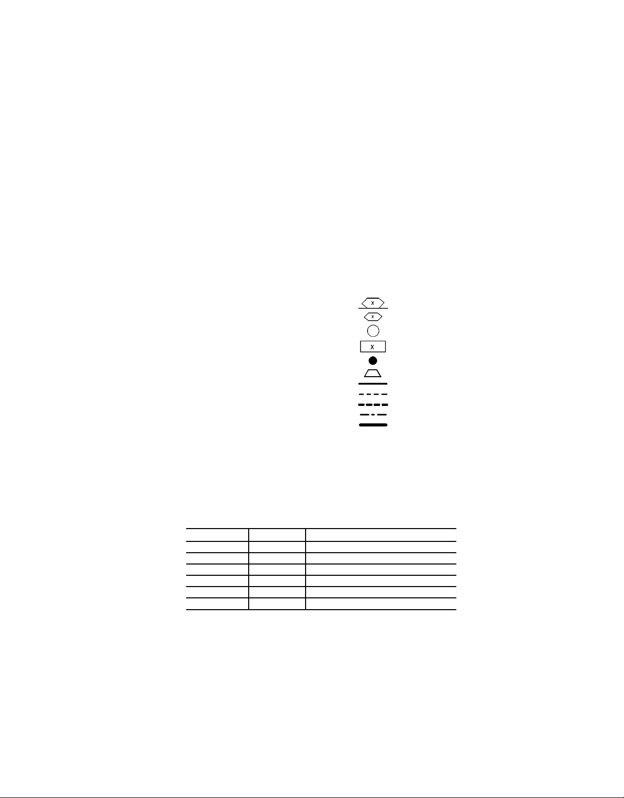
REMOTE CONTROL BOX CONDENSATE PREVENTION — When the remote control box is installed, precautions must be taken to prevent condensation from forming
inside the junction box mounted in the unit’s supply fan section. Standard installation practice is to mount the remote
control box adjacent to the air handling unit and then to enclose the Class II wiring in flexible conduit between the control box and the junction box in the fan section.
The sheet metal housing of the control box is not airtight,
therefore warm, moist air can migrate through the flexible
conduit to the junction box in the fan section. Condensate
can form inside the junction box and possibly on the terminal lugs.
To prevent moist air from migrating through the conduit,
seal the control wires inside the conduit at the remote control box enclosure. See Fig. 4. Use a nonconductive, nonhardening sealant. Permagum (manufactured by Schnee
Morehead) or sealing compound, thumb grade (manufactured by Calgon), are acceptable materials.
MakeElectrical Connections — 39L and 39NX units
have internal control wiring for the operation of the PIC section and its control devices. The control system requires a
dedicated 120 vac or 230 vac (50 or 60 Hz) power circuit
capable of providing a minimum of 10 amps (but not greater
than 20 amps) to the control box. The actual number of controls on one power source depends on the installation and
power circuit requirements. Do not run PIC power wiring in
the same conduit as sensor wiring or control wiring of fieldinstalled devices.
IMPORTANT: To ease installation, control wiring is
located on the service side of the unit with electrical
connectors provided at all unit separation points. If a
unit is separated into pieces for installation, rejoin all
connectors in their original alpha-numeric sequence upon
reassembly. Connectors for vertical fan sections that
are shipped out of the normal operating position must
also be joined at final assembly.
For units with an integral PIC section, all unit factory control wiring is internal. Only a small number of wires must be
field-installed. All internal wiring consists of plenum wires
which enter the rear of the control box through sealed fittings. Control wiring is 18 to 20 gage, 2-conductor twisted
pair.
The electrical power disconnect and fan motor starter are
field-supplied and installed. Connections are provided in the
control box to wire a field-supplied HOA (HANDS/OFF/
AUTOMATIC) switch. If an HOA switch is used, it must be
field-installed in the supply and return fan motor starter circuit. The factory-wired high-pressure switch (variable air volume only) and low-temperature thermostat options are energized when the supply fan circuit is powered.
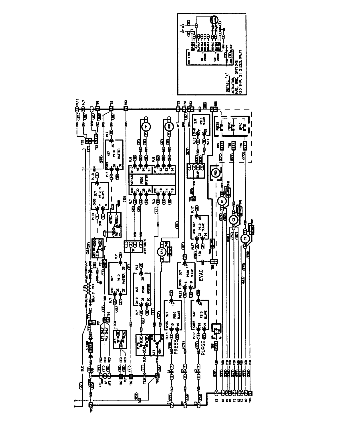
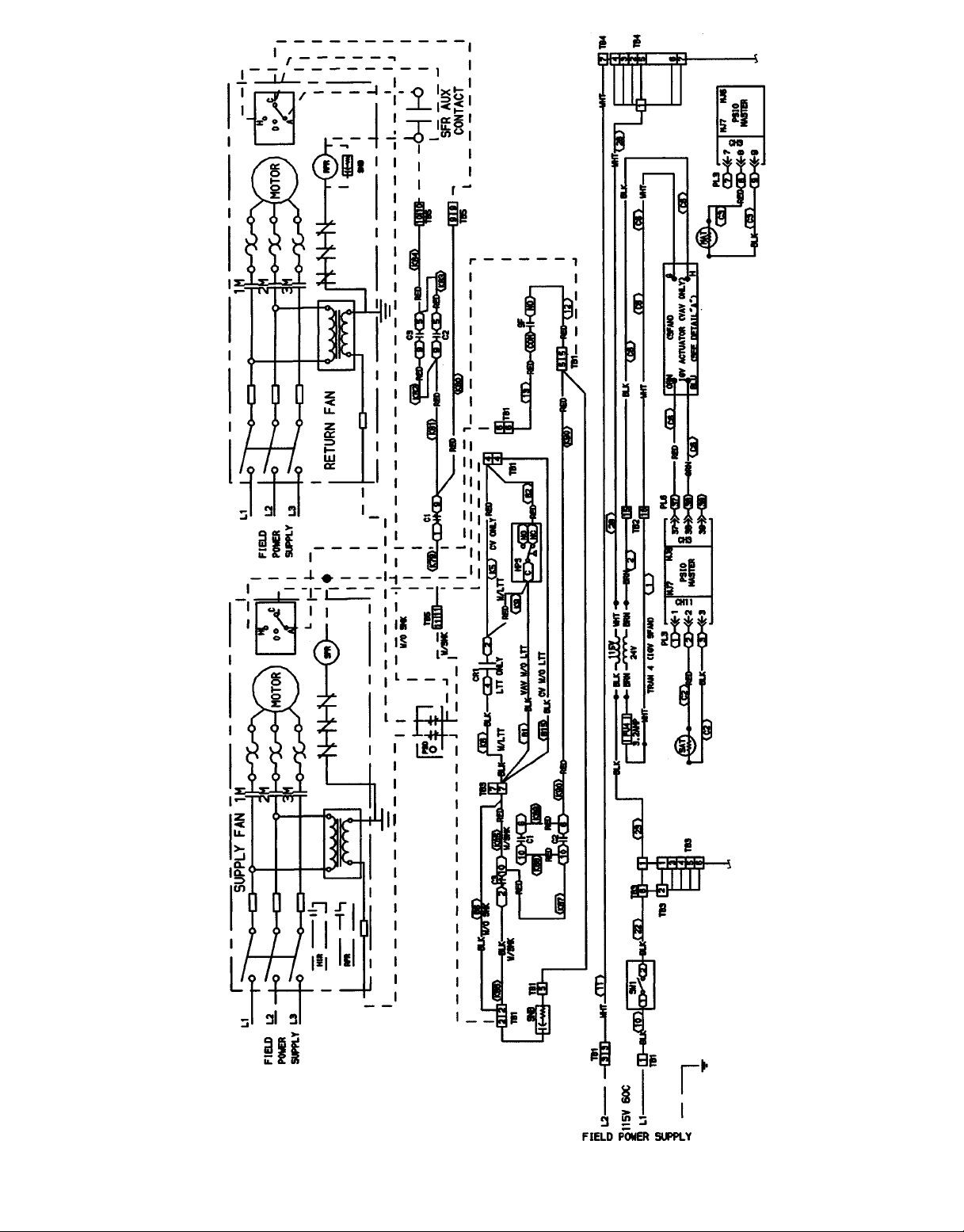
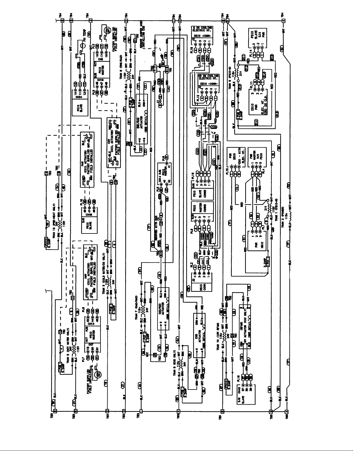
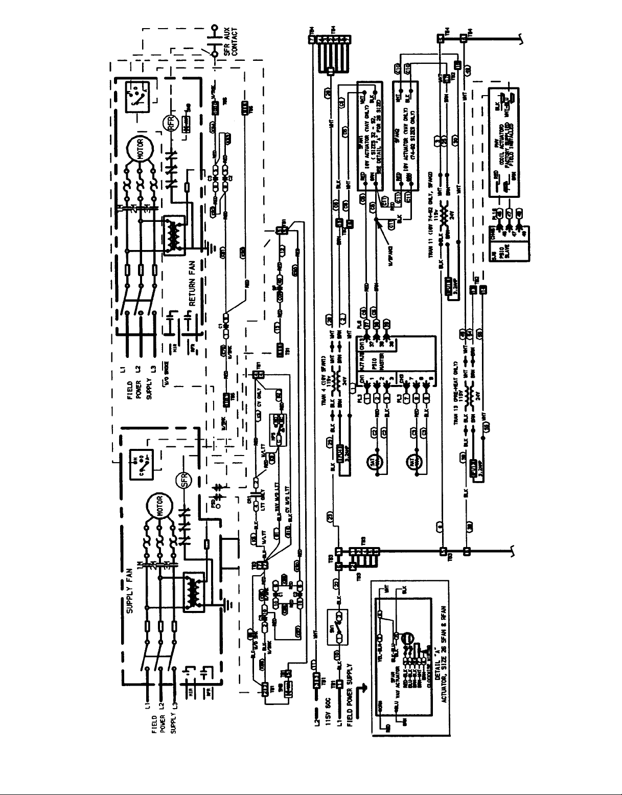
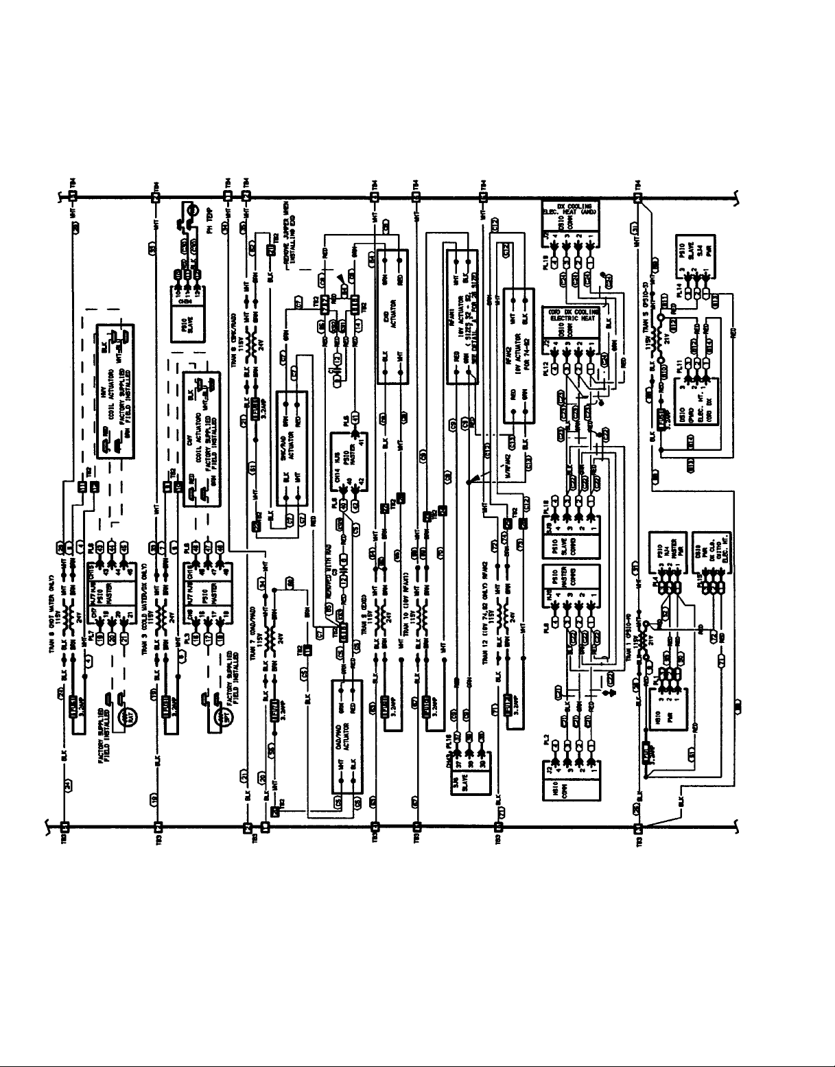
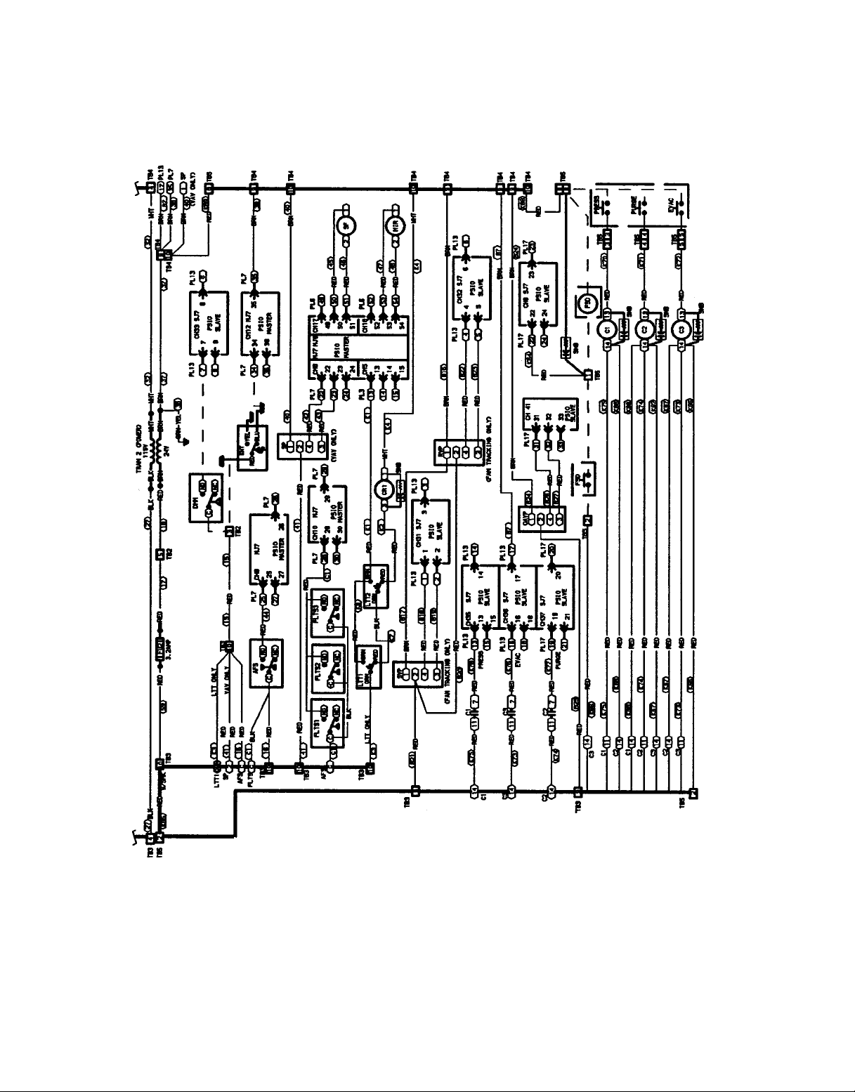
See Fig. 5-7 for control box component arrangements and
Fig. 8 for fan motor wiring. PIC input and output points are
listed in Table 1. Consult the wiring diagram located in the
control box or Fig. 9-12 for further details.
Power is present in the PIC control box in the motor
starter circuit even when the dedicated power to the PIC
control box is off.
The supply and return fan starter circuits are independent
from each other. Either circuit and its related control box
interface can have 24 vac, 120 vac, or 240 vac power.
All options that require a factory-installed transformer
are fused with 3.2 amp fuses on the secondary of each
transformer.
When the control box is shipped separately for remote mounting, all unit wiring terminates in a junction box located in
the fan section. Refer to Fig. 12 for the applicable wiring
diagram and Table 2 for junction box connections.
If the unit is provided with a factory-installed smoke control option, refer to the section titled Field-Wiring Connections, Smoke Control Option, page 54.
All PIC electrical components are UL (Underwriters’Laboratories) listed. The electronic modules are approved under
UL HVACEquipment Standard 873. PIC units are listed and
labeled by ETL (Engineering Testing Laboratory) to comply
with UL Standard 1995 for heating and cooling units, and
comply with NFPA (National Fire Protection Association)
Standard 90A.
3
LEGEND
ABX — Air Blender
AF — Airfoil
CV — Constant Volume
IGV — Inlet Guide Vanes
FC — Forward-Curved
FMB — Filter Mixing Box
MXB — Mixing Box
PIC — Product Integrated Controls
VAV — Variable Air Volume
*The cv capacity rating is the flow (gpm) through a valve at 1 psi pres-
sure drop.
Fig. 1 — Basic PIC Order Number
4
LEGEND
AF — Airfoil
CV — Constant Volume
DX — Direct Expansion
FC — Forward-Curved
FMB — Filter Mixing Box
MXB — Mixing Box
N.C. — Normally Closed
N.O. — Normally Open
PIC — Product Integrated Controls
VAV — Variable Air Volume
*The cv capacity rating is the flow (gpm) through a
valve at 1 psi pressure drop.
Fig. 2 — PIC Option Order Number
5
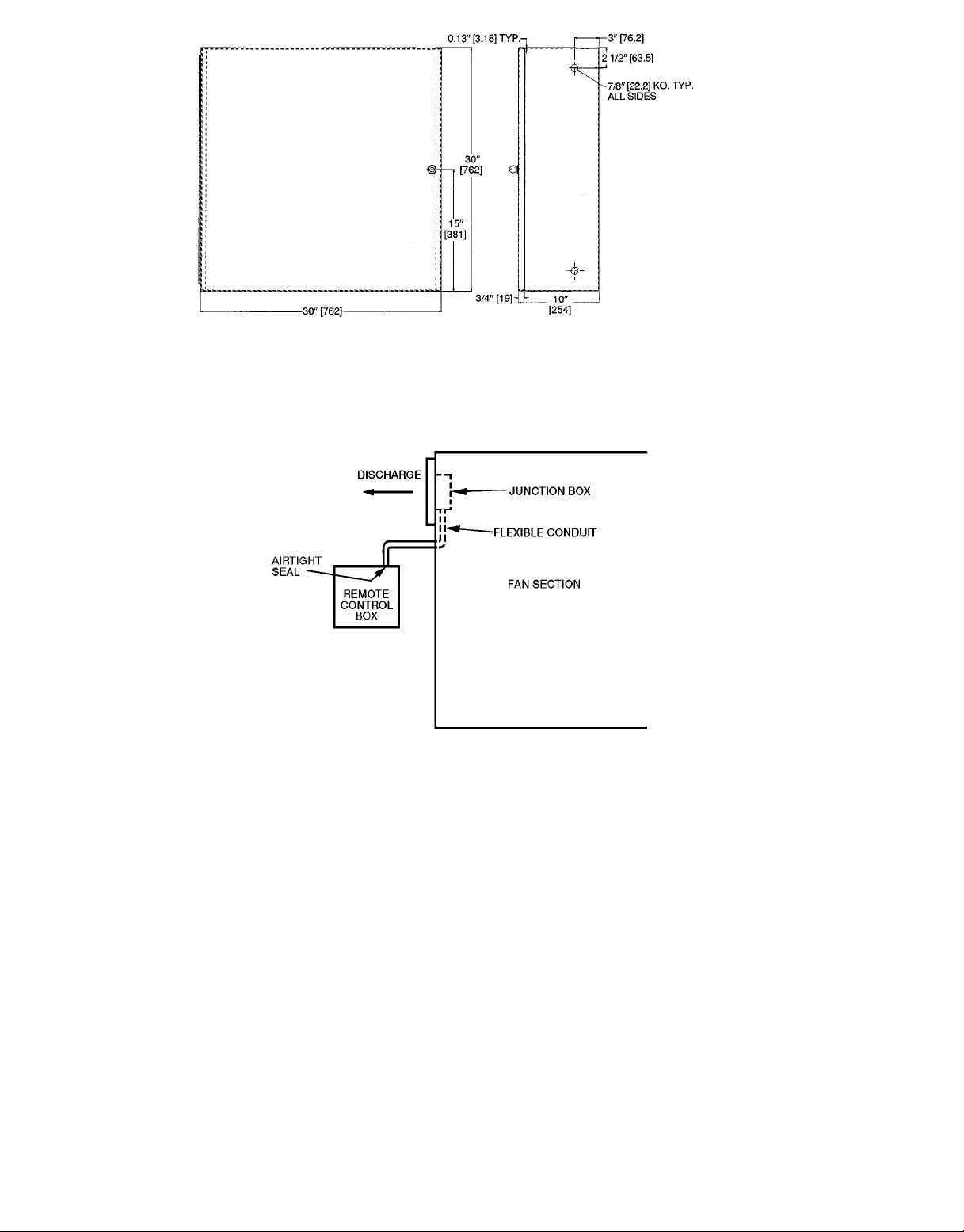
NOTE: Dimensions in [ ] are in millimeters.
Fig. 3 — Control Box for Remote Mounting
Fig. 4 — Sealing Control Wiring in Flexible Conduit
6
LEGEND (Fig. 5-12, Table 2)
AFS — Airflow Switch
AO — Analog Output
AOTC — Analog Output Temperature Control
AQ
AQ
C—Contactor
CCW — Counterclockwise
CH — Channel
CR — Control Relay
CUST — Condensing Unit Status
CV — Constant Volume
CW — Clockwise
CWV — Chilled Water Valve
DHH — Duct High Humidity
DO — Discrete Output
DOTC — Discrete Output Temperature Control
DSIO — Control Module, Electric Heat and/or DX
DTCC — Discrete Time Clock Control
DX — Direct Expansion
DXS — DX Cooling Stage
DXSD — Direct Expansion Cooling Shutdown
EHS — Electric Heaters
ELEC — Electric
ENT — Enthalpy Switch
EQUIP — Equipment
EVAC — Smoke Evacuation Input
EXD — ExhaustAir Damper Actuator
FLTS — Filter Status Switch
FSD — Fire Shutdown Device
FU — Fuse
GND — Ground
HIR — Heat Interlock Relay
HOA — Hand-Off-Auto. Switch
HPS — High-Pressure Switch
HSIO — Keyboard and Display Module
HT — Heat
HUM — Humidifier
HWV — Hot Water Valve
IGV — Inlet Guide Vane Actuator
LTT — Low Temperature Thermostat
MAD — Mixed-Air Damper Actuator
MAT — Mixed-Air Temperature
MPSIO — Master Processor Module
OAD — Outdoor-Air Damper Actuator
OARH — Outdoor-Air Relative Humidity
OAT — Outdoor-Air Temperature
OAVP — Outdoor-Air Velocity Pressure
— Air Quality Sensor, No. 1
1
— Air Quality Sensor, No. 2
2
(Processor Module)
OT — Outside-Air Thermostat
PH — Preheat
PL — Plug Assembly
PRESS — Smoke Pressurization Input
PSIO — Processor Module
PURG — Smoke Purge Input
RAD — Return-Air Damper Actuator
RAT — Return-Air Temperature
RFAN — Return Fan
RFR — Return Fan Relay
RFVC — Return Fan Volume Control
RH — Relative Humidity
RVP — Return Velocity Pressure
SAT — Supply-Air Temperature
SF — Fan Status Relay
SFAN — Supply Fan
SFR — Supply Fan Relay
SMK — Smoke
SNB — Snubber
SP — Static Pressure Transducer
SPSIO — Slave Processor Module
SPT — Space Temperature
SVP — Supply Velocity Pressure
SW — Switch
TB — Terminal Block Terminal
TEMP — Temperature
TRAN — Transformer
VAV — Variable Air Volume
W/ — With
WO/ — Without
(Option Module)
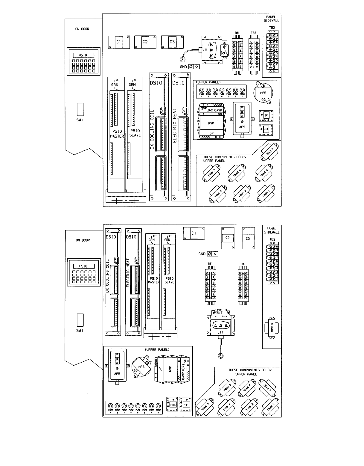
Marked Wire or Cable
Terminal (Marked)
Terminal (Unmarked)
Terminal Block
Splice (Factory)
Splice (Field)
Wiring Factory
Wiring Field Control
Wiring Field Power
Option or Accessory
Common Potential
NOTES:
1. Use copper conductors only.
2. Wire is in accordance with National Electrical Code (NEC).Forlocalcodes,
replace original wires with 90 C wire or its equivalent.
3. Replace wires fromIGV, FLTS,MAT,SAT,OAD,RAD,andELEC HTwith
125 C plenum cable conductor as required.
4. Input channel numbers and points for configuration of the optional
analog output temperature control (AOTC) follow:
CHANNEL SENSOR DESCRIPTION
1 SAT Supply-Air Temperature
2 OAT Outdoor-Air Temperature
3 MAT Mixed-Air Temperature
6 SPT Space-Air Temperature
7 RAT Return-Air Temperature
34 TEMP Preheat or Optional Carrier Sensor
5. Reference for wire markers, where ‘X’ represents a numeral:
X — Item number on wiring harness
BX — Box wire
CX — Cable
KX — Accessory kit wire
7
ARRANGEMENT FOR SIZES 03 AND 06
ARRANGEMENT FOR SIZES 08 THROUGH 35
Fig. 5 — PIC Section Control Box Component Arrangements, 39L
8
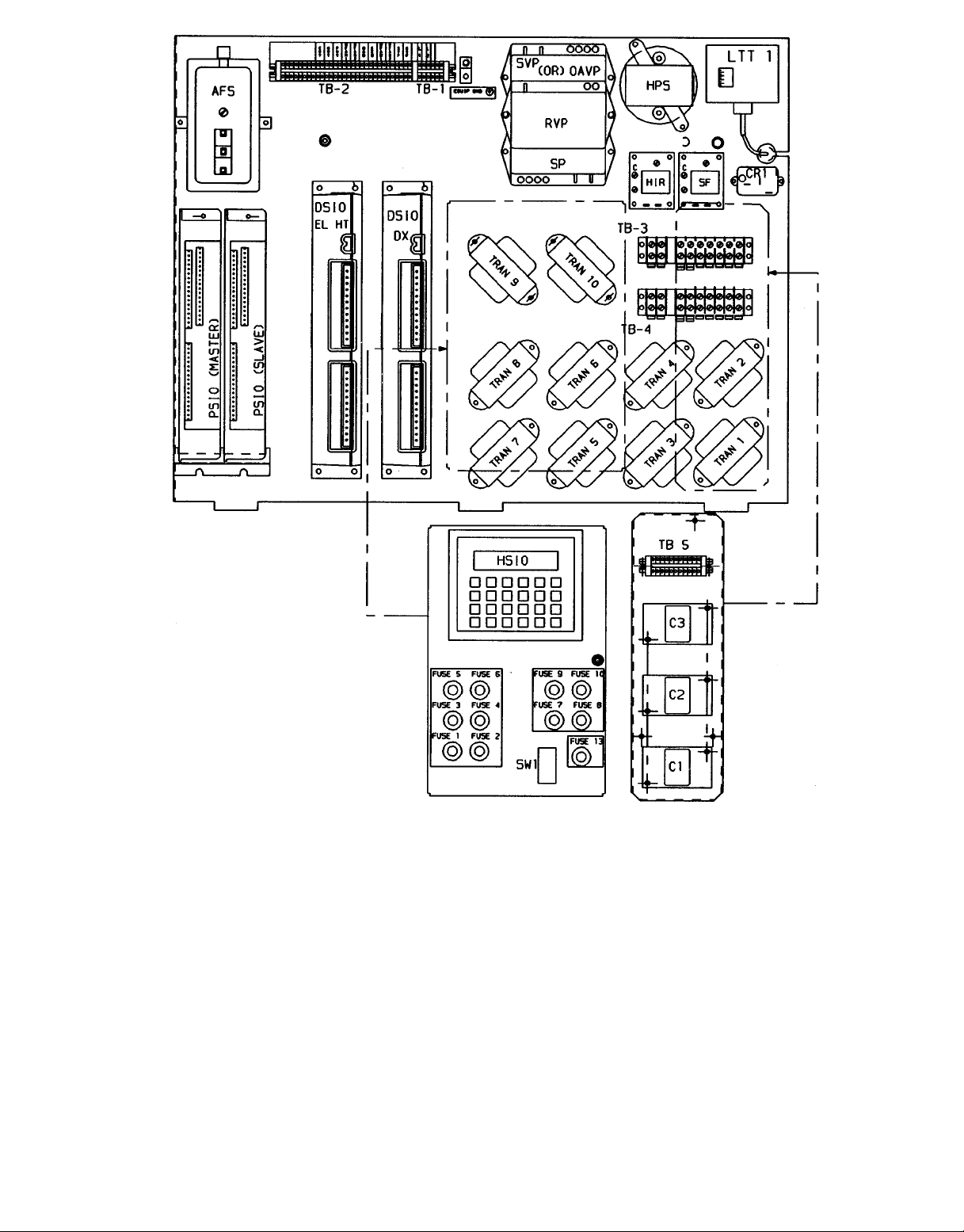
Fig. 6 — PIC Section Control Box Component Arrangement, 39NX Sizes 07-21
9
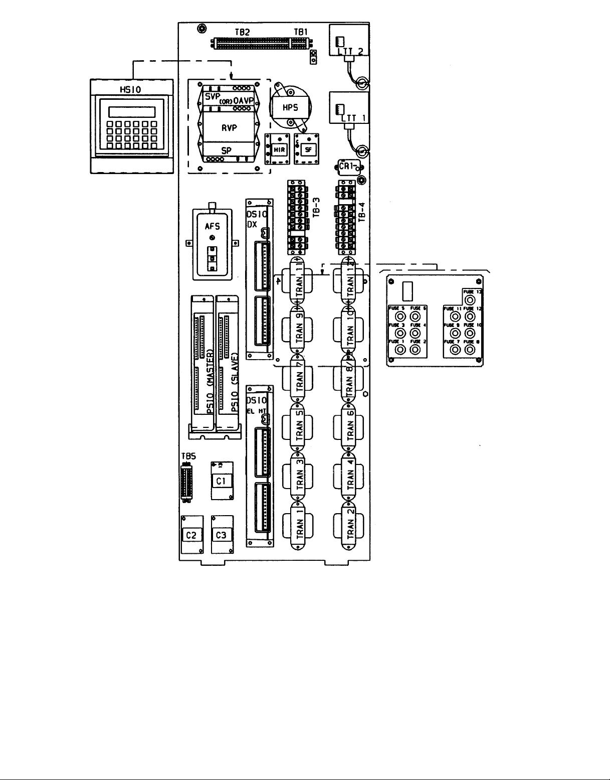
Fig. 7 — PIC Section Control Box Component Arrangement, 39NX Sizes 26-92
10
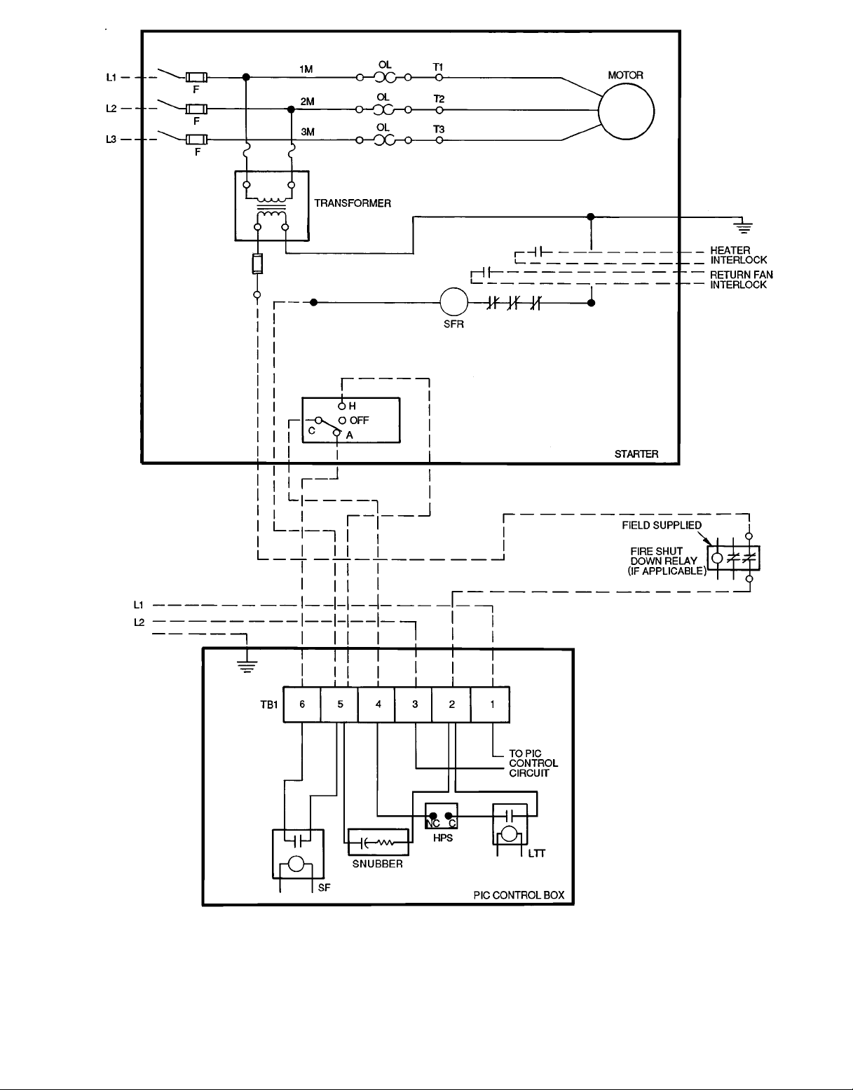
Fig. 8 — Fan Motor Starter Circuit and PIC Control Wiring Interface — PIC Power for
Control Circuit From Dedicated Source
11

MODULE,
DEFAULT ADDRESS
PSIO (Processor)
ADDRESS 1
PSIO (Option)
ADDRESS 31
DSIO (Electric Heat)
ADDRESS 19
DSIO (DX without
Electric Heat)
ADDRESS 19
DSIO (DX with
Electric Heat)
ADDRESS 49
Table 1 — Input and Output Points
INPUT
SAT AI 1 IGV* AO 13
OAT AI 2 MIXD AO, DO† 14
MAT AI 3 HWC AO 15
RH AI 4 CWC AO 16
LTT DI 5 SF DO 17
SPT AI 6 HIR* DO 18
RAT AI 7 — — —
SP* AI 8 — — —
AFS DI 9 — — —
FLTS DI 10 — — —
OARH AI 11 — — —
ENT DI 12 — — —
SVP* AI 31 RFVC* AO 43
RVP* AI 32 HUM1 AO, DO 44
DHH DI 33 HUM2 DO 45
TEMP AI 34 AOTC AO 46
PRES DI 35 DOTC DO 47
EVAC DI 36 DTCC DO 48
PURG DI 37 — — —
FSD DI 38 — — —
AQ1 AI 39 — — —
AQ2 AI 40 — — —
OAVP* AI 41 — — —
METER DI 42 — — —
— — — EHS1 DO 23
— — — EHS2 DO 24
— — — EHS3 DO 25
— — — EHS4 DO 26
— — — EHS5 DO 27
— — — EHS6 DO 28
— — — EHS7 DO 29
— — — EHS8 DO 30
CUST DI 19 DXS1 DO 23
DXSD DI 20 DXS2 DO 24
— — — DXS3 DO 25
— — — DXS4 DO 26
— — — DXS5 DO 27
— — — DXS6 DO 28
— — — DXS7 DO 29
— — — DXS8 DO 30
CUST DI 49 DXS1 DO 53
DXSD DI 50 DXS2 DO 54
— — — DXS3 DO 55
— — — DXS4 DO 56
— — — DXS5 DO 57
— — — DXS6 DO 58
— — — DXS7 DO 59
— — — DXS8 DO 60
INPUT
TYPE
CHANNEL
NUMBER
OUTPUT
OUTPUT
TYPE
CHANNEL
NUMBER
AFS — Airflow Switch (Supply Fan
AI — Analog Input
AO — Analog Output
AOTC — Analog Output Temperature
AQ1, 2 — Air Quality Sensors 1, 2
CUST — Condensing Unit Status
CWC — Chilled Water Coil
DI — Discrete Input
DHH — Duct High Humidity
DO — Discrete Output
DOTC — Discrete Output Temperature
DTCC — Discrete Output Timeclock
*Available on VAV only.
†Discrete output with two-position damper control.
Status Switch)
Control
(Outdoor Air Thermostat)
Control
Control
LEGEND
DXS1-8 — Direct Expansion Cooling
DXSD — Direct Expansion Cooling
EHS1-8 — Electric Heater Stages 1-8
ENT — Enthalpy Switch
EVAC — Evacuation
FLTS — Filter Status Switch
FSD — Fire Shutdown
HIR — Heat Interlock Relay
HWC — Hot Water Coil
HUM1, 2 — Humidity Stages 1, 2
IGV — Inlet Guide Vanes
LTT — Low Temperature Thermostat
MAT — Mixed-Air Temperature
METER — Meter (Pulsed Dry-Contact
Stages 1-8
Shutdown
(also labelled FRZ)
Input)
12
MIXD — Mixed-Air Dampers
OARH — Outdoor-Air Relative Humidity
OAT — Outdoor-Air Temperature
OAVP — Outdoor-Air Velocity Pressure
PRES — Pressurization
PURG — Purge
RAT — Return-Air Temperature
RFVC — Return Fan Volume Control
RH — Relative Humidity
RVP — Return Velocity Pressure
SAT — Supply-Air Temperature
SF — Supply Fan Relay
SP — Static Pressure
SPT — Space Temperature
SVP — Supply Velocity Pressure
TEMP — Optional Temperature Input
13
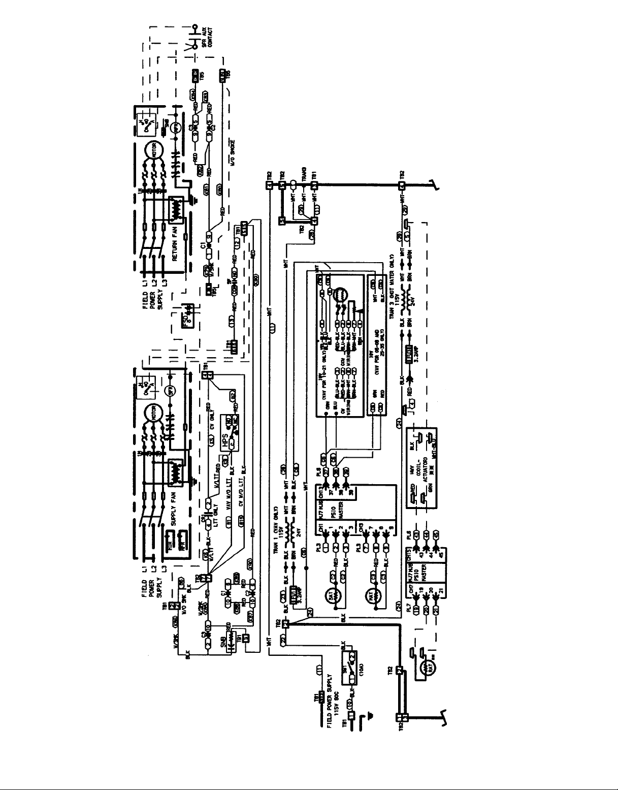
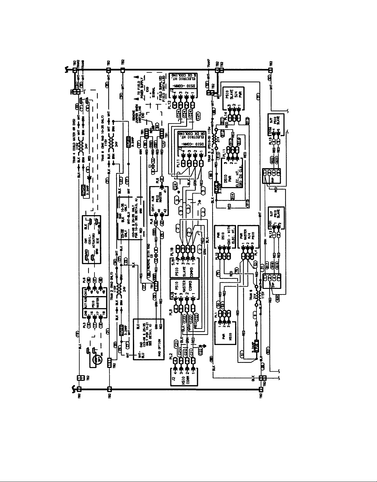
Fig. 9 — Unit Wiring Schematic, 39L Sizes 03-35 (115 v, Typical)
14
Fig. 9 — Unit Wiring Schematic, 39L Sizes 03-35 (115 v, Typical) (cont)
15
Fig. 9 — Unit Wiring Schematic, 39L Sizes 03-35 (115 v, Typical) (cont)
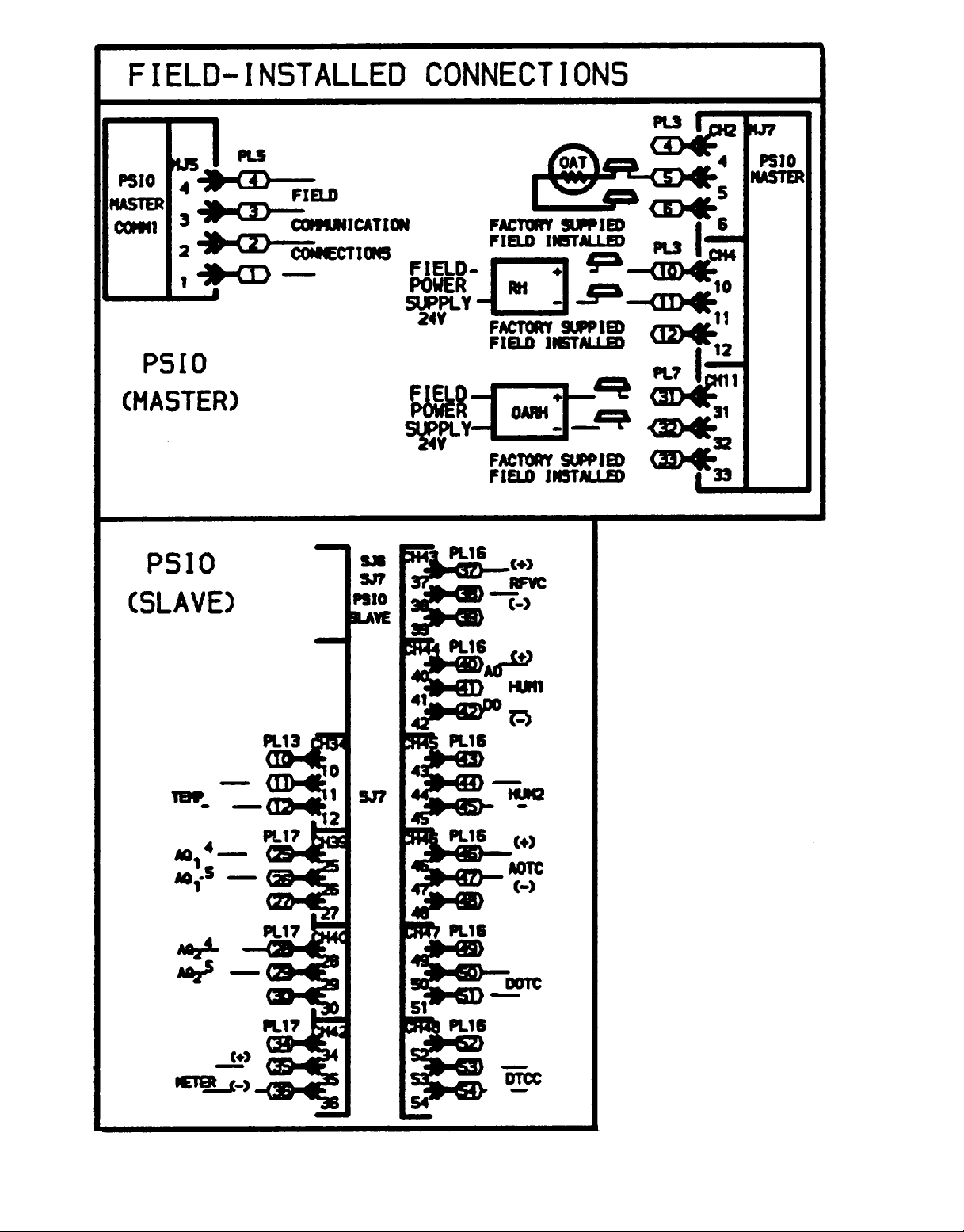
Fig. 9 — Unit Wiring Schematic, 39L Sizes 03-35 (115 v, Typical) (cont)
16
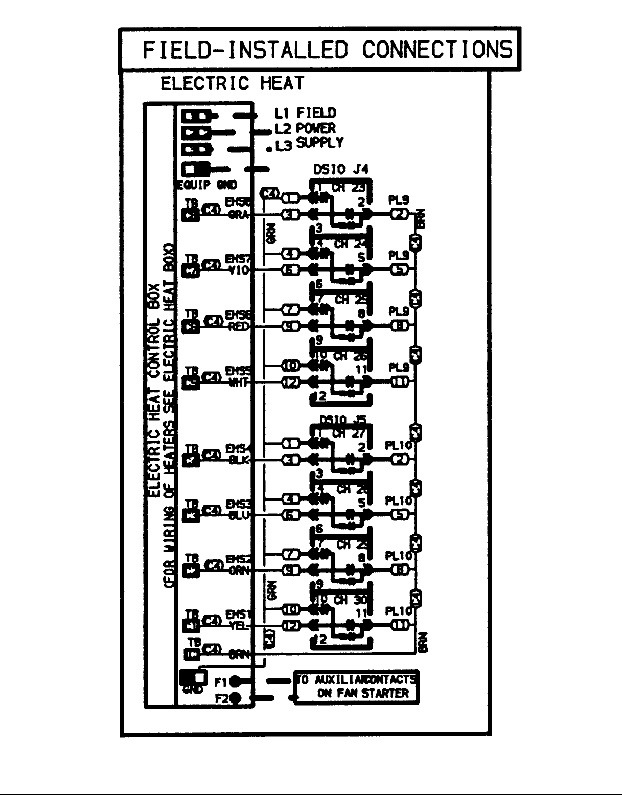
Fig. 9 — Unit Wiring Schematic, 39L Sizes 03-35 (115 v, Typical) (cont)
17
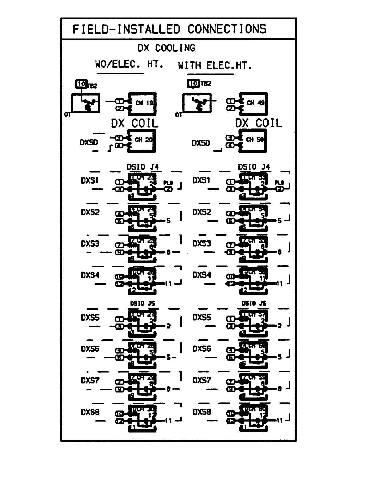
Fig. 9 — Unit Wiring Schematic, 39L Sizes 03-35 (115 v, Typical) (cont)
18
19
Fig. 10 — Unit Wiring Schematic, 39NX Sizes 07-21 (115 v, Typical)
20
Fig. 10 — Unit Wiring Schematic, 39NX Sizes 07-21 (115 v, Typical) (cont)

21
Fig. 10 — Unit Wiring Schematic, 39NX Sizes 07-21 (115 v, Typical) (cont)
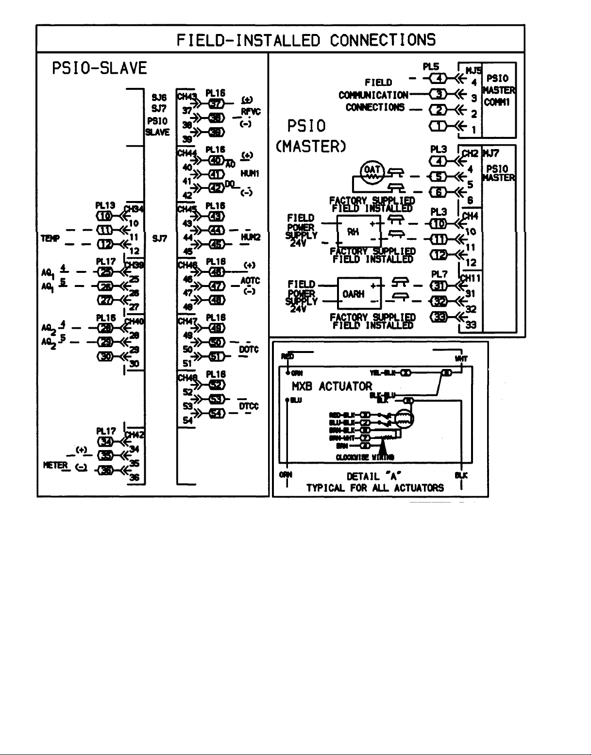
Fig. 10 — Unit Wiring Schematic, 39NX Sizes 07-21 (115 v, Typical) (cont)
22
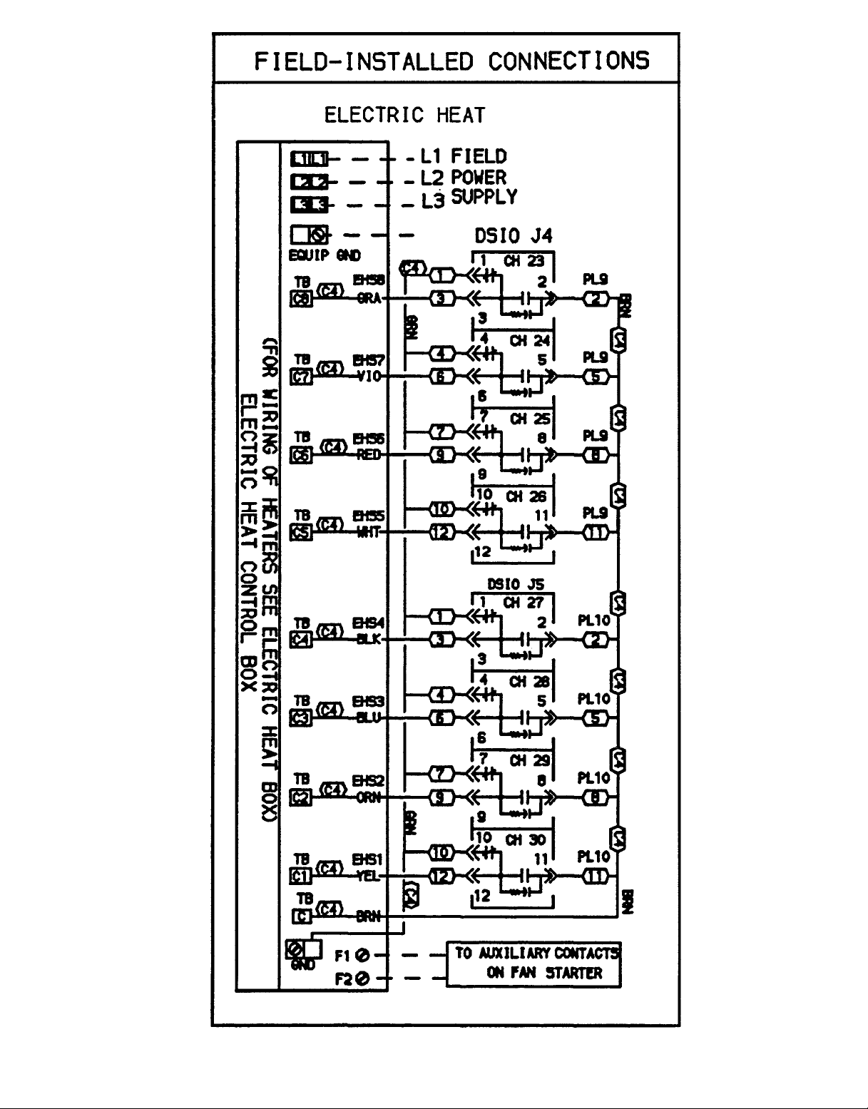
Fig. 10 — Unit Wiring Schematic, 39NX Sizes 07-21 (115 v, Typical) (cont)
23
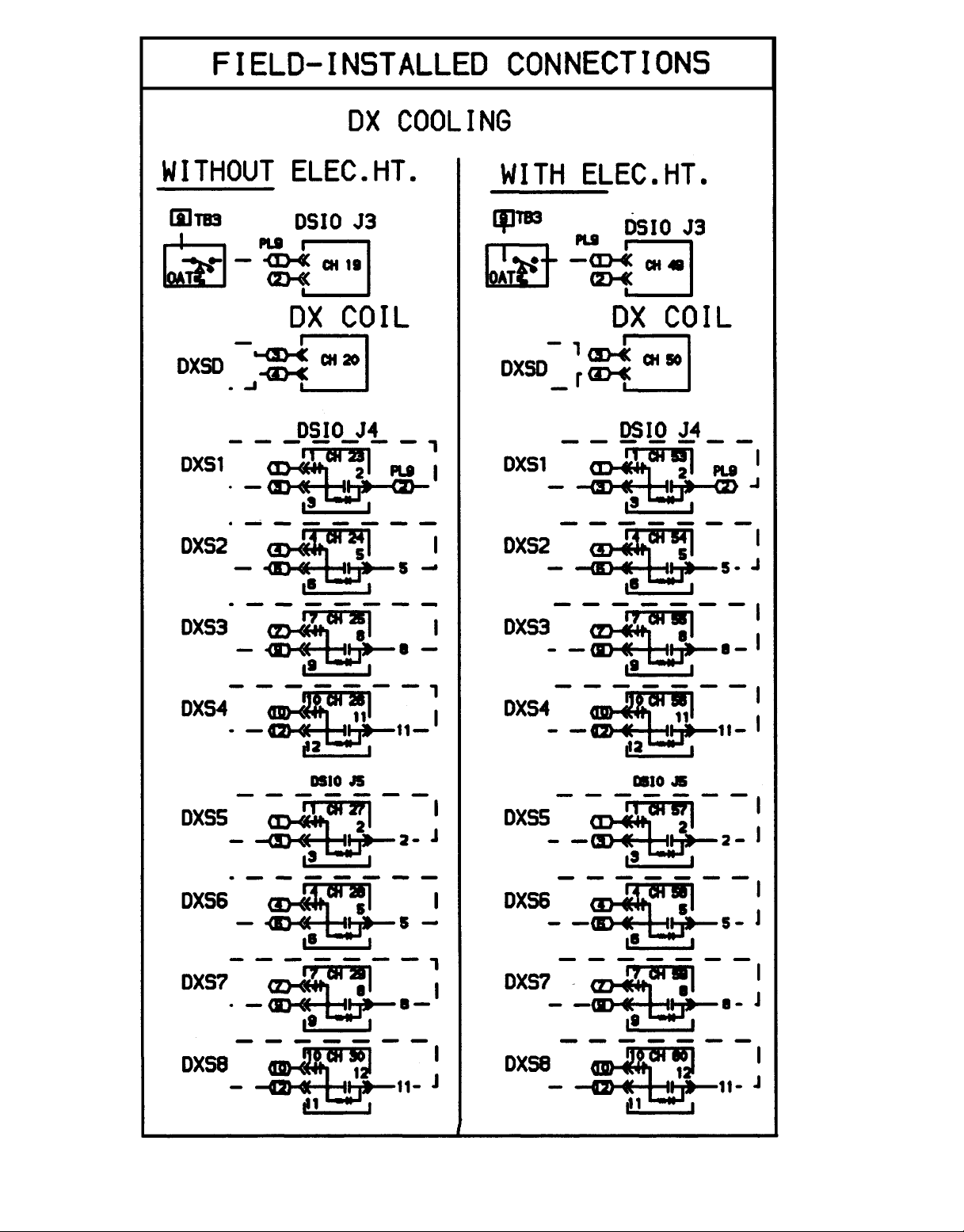
Fig. 10 — Unit Wiring Schematic, 39NX Sizes 07-21 (115 v, Typical) (cont)
24
25
Fig. 11 — Unit Wiring Schematic, 39NX Sizes 26-92 (115 v, Typical)
26
Fig. 11 — Unit Wiring Schematic, 39NX Sizes 26-92 (115 v, Typical) (cont)
27
Fig. 11 — Unit Wiring Schematic, 39NX Sizes 26-92 (115 v, Typical) (cont)
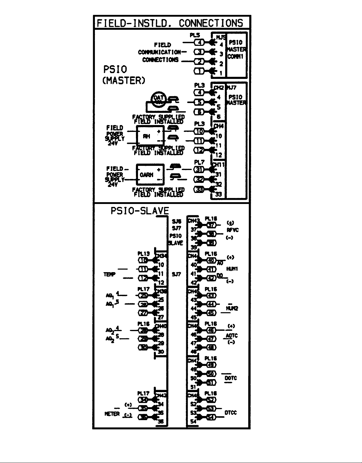
Fig. 11 — Unit Wiring Schematic, 39NX Sizes 26-92 (115 v, Typical) (cont)
28
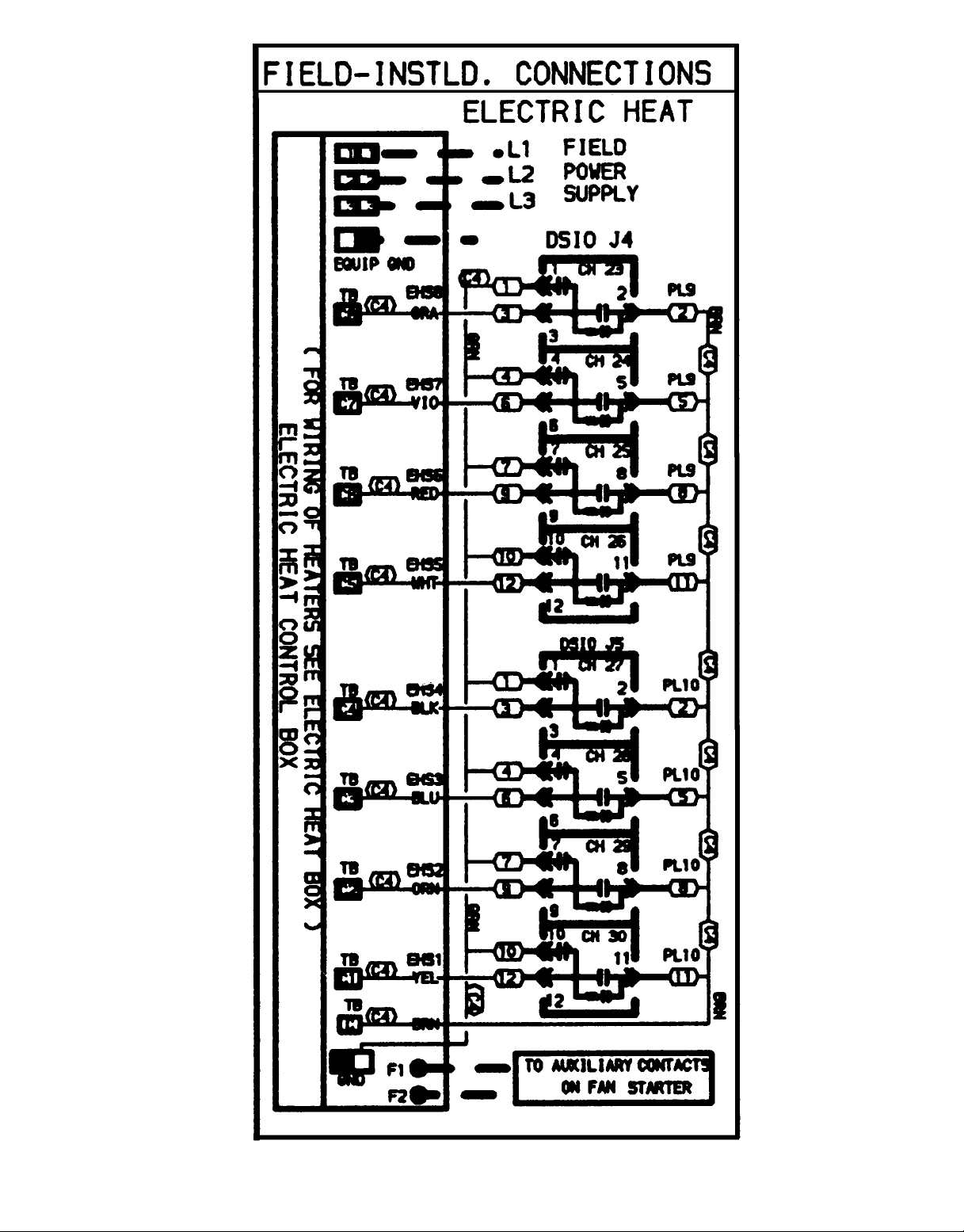
Fig. 11 — Unit Wiring Schematic, 39NX Sizes 26-92 (115 v, Typical) (cont)
29
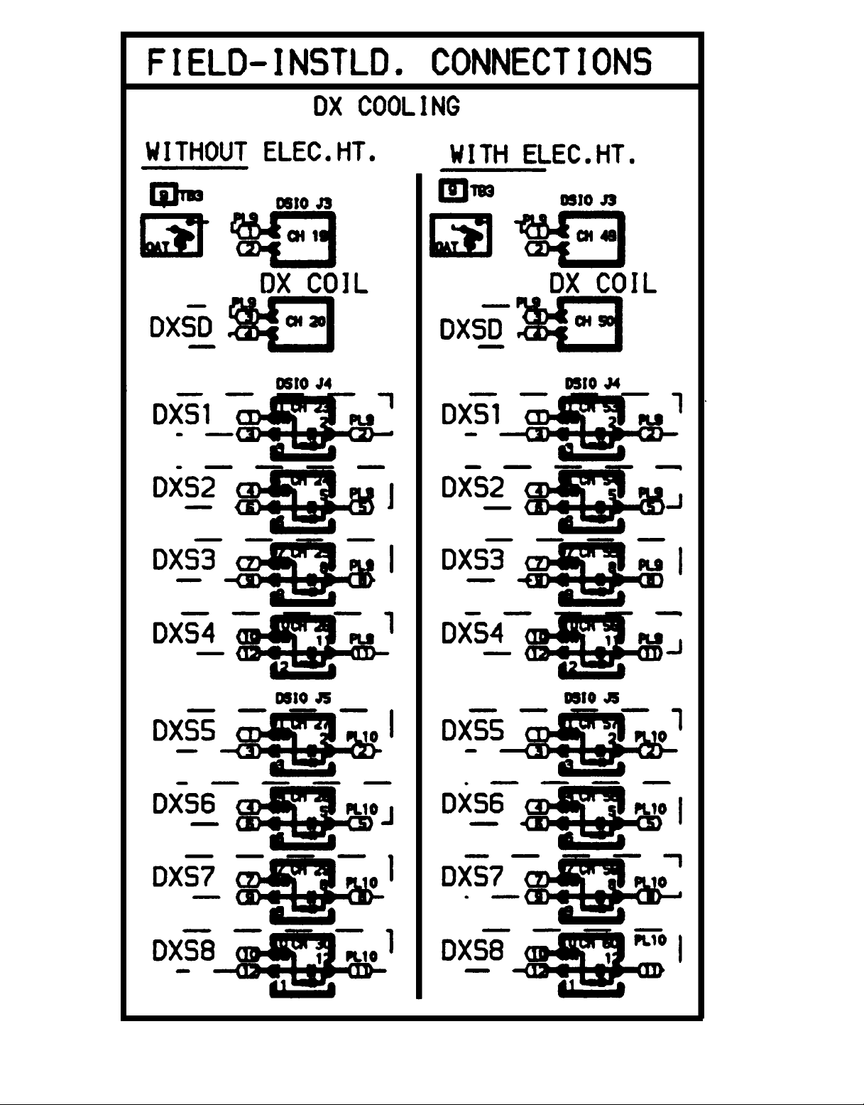
Fig. 11 — Unit Wiring Schematic, 39NX Sizes 26-92 (115 v, Typical) (cont)
30
 Loading...