


38HDF018-036 Duct Free Condensing Units 38HDR018-060 Ducted Condensing Units
Installation, Start-Up and
Service Instructions
CONTENTS
Page
SAFETY CONSIDERATIONS . . . . . . . . . . . . . . . . . . . . . . 1
INSTALLATION . . . . . . . . . . . . . . . . . . . . . . . . . . . . . . . . 1-10
Step 1 — Complete Pre-Installation Checks . . . . . . 1
•UNPACK UNIT
•INSPECT SHIPMENT
•CONSIDER SYSTEM REQUIREMENTS
•MATCHING THE CONDENSING UNIT TO AN INDOOR UNIT
Step 2 — Rig and Mount Unit. . . . . . . . . . . . . . . . . . . . . 3
•MOUNTING ON GROUND
•MOUNTING ON ROOF
•RIGGING
Step 3 — Complete Refrigerant Piping
Connections . . . . . . . . . . . . . . . . . . . . . . . . . . . . . . . . . . . 3
•CHECK ACCURATER CONTROL
•FILTER DRIER
•MAKE PIPING SWEAT CONNECTORS
•PROVIDE SAFETY RELIEF
Step 4 — Make Electrical Connections . . . . . . . . . . . 6
•CONTROL CIRCUIT WIRING
•POWER WIRING
•CONNECTIONS TO DUCT-FREE FAN COIL UNITS
START-UP . . . . . . . . . . . . . . . . . . . . . . . . . . . . . . . . . . . . . . . 11 SERVICE . . . . . . . . . . . . . . . . . . . . . . . . . . . . . . . . . . . . . 11-14 MAINTENANCE . . . . . . . . . . . . . . . . . . . . . . . . . . . . . . . . . 14 TROUBLESHOOTING. . . . . . . . . . . . . . . . . . . . . . . . . .14,15
SAFETY CONSIDERATIONS
Installing and servicing air conditioning equipment can be hazardous due to system pressure and electrical components. Only trained and qualified service personnel should install or service air conditioning equipment.
Untrained personnel can perform basic maintenance, such as cleaning and replacing filters. All other operations should be performed by trained service personnel. When working on air conditioning equipment, observe safety precautions in literature, tags, and labels attached to unit.
Follow all safety codes. Wear safety glasses and work gloves. Use quenching cloth for brazing operations. Have fire extinguisher available. Read these instructions thoroughly. Consult local building codes and the National Electrical Code (NEC) for special installation requirements.
Before installing or servicing system, always turn off main power to system. There may be more than one disconnect switch. Turn off accessory heater power if applicable. Electrical shock can cause serious personal injury.
Puron® (R-410A) refrigerant systems operate at higher pressures than standard R-22 systems. Do not use R-22 service equipment or components on Puron refrigerant equipment. If service equipment is not rated for Puron refrigerant, equipment damage or personal injury may result.
INSTALLATION
Step 1 — Complete Pre-Installation Checks
UNPACK UNIT (See Fig. 1) — Move the unit to final location. Remove unit from carton, being careful not to damage service valves and grilles.
Fig. 1 — 38HDF,HDR Unit
INSPECT SHIPMENT — File a claim with the shipping company if shipment is damaged or incomplete. Check unit nameplate to ensure unit matches job requirements.
CONSIDER SYSTEM REQUIREMENTS — Consult local building codes and NEC for special installation requirements.
Allow sufficient space for airflow clearance, wiring, refrigerant piping, and servicing unit. See Fig. 2.
Locate unit so that condenser airflow is unrestricted on both sides. Refer to Fig. 2.
Unit may be mounted on a level pad directly on base legs or mounted on raised pads at support points. See Fig. 2 for center of gravity.
MATCHING THE CONDENSING UNIT TO AN INDOOR UNIT — The 38HDF,HDR units can be matched to a corresponding indoor unit. The 38HDF018-036 units can be matched with an in-ceiling cassette or high wall indoor unit. The 38HDR unit can be matched with under-ceiling and residential fan coils. Refer to separate indoor unit literature for more information.
Manufacturer reserves the right to discontinue, or change at any time, specifications or designs without notice and without incurring obligations.
Book |
1 |
4 |
Catalog No. 02-38HD0001-SI |
Printed in U.S.A. |
Form 38HD-4SI |
Pg 1 |
1-06 |
Replaces: 38HDC-3SI |
Tab |
3e |
2f |
|
|
|
|
|
|
|
|
|
|
|
|
|
|
|

2
UNIT MODELS |
CHASSIS |
|
|
|
|
|
|
|
|
|
|
|
|
|
UNIT SIZE |
M |
|
OPERATING WT |
||||
38HDF |
38HDR |
SIZE |
A |
B |
C |
D |
E |
F |
G |
H |
J |
K |
L |
N |
P |
in. |
mm |
lb |
kg |
|||
|
|
|||||||||||||||||||||
Unit Size |
Unit Size |
(Reference) |
2′-11/8″ |
3′-015/16″ 1′-29/16″ |
1′-4″ |
1′-117/16″ |
1′-53/16″ 1′-51/8″ |
1′-10″ |
1′-1″ |
0′-65/8″ |
0′-111/4″ 0′-215/16″ |
0′-6″ |
|
018 |
5/8 |
15.88 |
166 |
75.3 |
||||
|
|
|
|
|||||||||||||||||||
018 |
018 |
0 |
|
024 |
5/8 |
15.88 |
176 |
79.8 |
||||||||||||||
(638.2) |
(938.2) |
(369.9) |
(406.4) |
(595.3) |
(436.6) |
(435) |
(559.1) |
(330.2) |
(168.3) |
(285.8) |
(75) |
(152.4) |
38HDF |
|||||||||
|
|
|
2′-71/8″ |
3′-015/16″ |
1′-29/16″ |
1′-4″ |
1′-117/16″ |
1′-53/16″ |
1′-111/8″ |
2′-4″ |
1′-2″ |
0′-63/4″ |
0′-115/8″ |
0′-215/16″ |
0′-6″ |
030 |
3/4 |
19.05 |
187 |
84.8 |
||
024,030 |
024 |
0.6 |
|
|||||||||||||||||||
(790.6) |
(938.2) |
(369.9) |
(406.4) |
(595.3) |
(436.6) |
(587.4) |
(711.5) |
(355.6) |
(171.5) |
(295.3) |
(75) |
(152.4) |
|
036 |
3/4 |
19.05 |
250 |
113.4 |
||||
|
|
|
|
|||||||||||||||||||
036 |
030,036 |
1.0 |
3′-13/16″ |
3′-89/16″ 1′-51/16″ |
1′-67/16″ |
2′-61/2″ |
1′-75/8″ 2′-53/16″ |
2′-101/16″ |
1′-111/16″ 0′-81/8″ |
1′-37/8″ 0′-37/16″ |
0′-61/2″ |
|
018 |
5/8 |
15.88 |
166 |
75.8 |
|||||
|
|
|
(944.6) |
(1131.9) |
(433.4) |
(468.3) |
(774.7) |
(498.5) |
(741) |
(865.5) |
(347.7) |
(206.4) |
(403.2) |
(88) |
(165.4) |
|
024 |
5/8 |
15.88 |
176 |
79.8 |
|
— |
048,060 |
1.6 |
3′-73/16″ |
3′-89/16″ 1′-51/16″ |
1′-67/16″ |
2′-61/2″ |
1′-75/8″ 2′-113/16″ |
3′-41/16″ |
1′-21/2″ 0′-81/2″ |
1′-67/8″ 0′-37/16″ |
0′-61/2″ |
|
||||||||||
|
030 |
3/4 |
19.05 |
187 |
84.8 |
|||||||||||||||||
(1097) |
(1131.9) |
(433.4) |
(468.3) |
(774.7) |
(498.5) |
(893.4) |
(1017.9) |
(354.2) |
(215.9) |
(479.4) |
(88) |
(165.4) |
38HDR |
|||||||||
NOTE: Dimensions shown in feet-inches. Dimensions in ( ) are millimeters. |
|
|
|
|
|
|
|
|
|
|
036 |
3/4 |
19.05 |
250 |
113.4 |
|||||||
|
|
|
|
|
|
|
|
|
|
|
||||||||||||
|
|
|
|
|
|
|
|
|
|
|
|
|
|
|
|
|
048 |
7/8 |
22.22 |
278 |
126.1 |
|
|
|
|
|
|
|
|
|
|
|
|
|
|
|
|
|
|
060 |
7/8 |
22.22 |
306 |
138.8 |
|
|
|
|
|
|
|
|
|
|
|
|
|
|
|
|
|
|
|
MINIMUM MOUNTING PAD |
|
|||
|
|
|
|
|
|
|
|
|
|
|
|
|
|
|
|
UNIT SIZE |
|
|
DIMENSIONS |
|
||
|
|
|
|
|
|
|
|
|
|
|
|
|
|
|
|
|
|
Support Feet |
|
|||
|
|
|
|
|
|
|
|
|
|
|
|
|
|
|
|
|
|
|
|
|||
|
|
|
|
|
|
|
|
|
|
|
|
|
|
|
|
|
|
ft-in. |
|
mm |
|
|
|
|
|
|
|
|
|
|
|
|
|
|
|
|
|
|
CHASSIS SIZES 0 & .6 |
1′-11″ x 3′-6″ |
584.2 x 1066.8 |
||||
|
|
|
|
|
|
|
|
|
|
|
|
|
|
|
|
CHASSIS SIZES 1 & 1.6 |
2′-0″ x 4′-2″ |
609.6 x 1270 |
||||
|
|
|
|
|
|
|
|
|
|
|
|
|
|
|
NOTES: |
|
|
|
|
|
||
|
|
|
|
|
|
|
|
|
|
|
|
|
|
|
1. Required clearances: with coil facing wall, allow 6 in. minimum clearance |
|||||||
|
|
|
|
|
|
|
|
|
|
|
|
|
|
|
|
on coil side and coil end, and 3 feet minimum clearance on compressor |
||||||
|
|
|
|
|
|
|
|
|
|
|
|
|
|
|
|
end and fan side. With fan facing wall, allow 8 in. minimum clearance on |
||||||
|
|
|
|
|
|
|
|
|
|
|
|
|
|
|
|
fan side and coil end, and 3 feet minimum clearance on compressor end |
||||||
|
|
|
|
|
|
|
|
|
|
|
|
|
|
|
|
and coil side. With multi-unit application, arrange units so discharge of one |
||||||
|
|
|
|
|
|
|
|
|
|
|
|
|
|
|
|
does not enter inlet of another. |
|
|
|
|
||
|
|
|
|
|
|
|
|
|
|
|
|
|
|
|
2. Dimensions in parenthesis are in millimeters. |
|
|
|||||
|
|
|
|
|
|
|
|
|
|
|
|
|
|
|
3. |
Center of Gravity |
. |
|
|
|
|
|
(FIELD PROVIDED AND INSTALLED)
Fig. 2 — 38HDF,HDR Unit Dimensions
Step 2 — Rig and Mount Unit
MOUNTING ON GROUND — Mount unit on a solid, level concrete pad. Position unit so water or ice from roof does not fall directly onto unit. Accessory stacking kits can be used when units are to be stacked. See installation instructions provided with the accessory kit. Use field-provided snow stand or ice rack where prolonged subfreezing temperatures or heavy snow occurs.
If conditions or local codes require unit be fastened to a pad, 6 field-supplied tiedown bolts should be used and fastened through slots provided in unit mounting feet.
MOUNTING ON ROOF — Mount unit on a level platform or frame at least 6 in. above roof surface. Isolate unit and tubing from structure.
RIGGING
Be sure unit panels are securely in place prior to rigging. Loose unit panels could result in equipment damage or personal injury.
Keep the unit upright and lift unit using a sling. Use cardboard or padding under the sling, and spreader bars to prevent sling damage to the unit. See Fig. 3. See Fig. 2 for center of gravity reference. Install the unit so that the coil does not face into prevailing winds. If this is not possible and constant winds above 25 mph are expected, use accessory wind baffle. See installation instructions provided with the accessory kit.
NOTE: Accessory wind baffles should be used on all units with accessory low ambient temperature control.
Field-fabricated snow or ice stands may be used to raise unit when operation will be required during winter months. Units may also be wall mounted using the accessory wall-mounting kit.
Fig. 3 — Lifting Unit with Sling
Step 3 — Complete Refrigerant Piping Connections — Outdoor units may be connected to indoor units using field-supplied tubing of refrigerant grade and condition. See Tables 1A and 1B for correct line sizes. Do not use less than 10 ft of interconnecting tubing.
DO NOT BURY MORE THAN 36 IN. OF REFRIGERANT PIPE IN THE GROUND. If any section of pipe is buried, there must be a 6-in. vertical rise to the valve connections on the outdoor unit. If more than the recommended length is buried refrigerant may migrate to cooler, buried section during extended periods of system shutdown. This causes refrigerant slugging and could possibly damage the compressor at start-up.
When more than 50 ft of interconnecting tubing and more than 30 ft of vertical lift is used, consult the residential long line application instruction guide. For long-line applications, interconnecting lines over 100 ft must be installed with a liquid line solenoid. A liquid line solenoid may also be installed on some units to improve part-load efficiency. Refer to the ARI (Air Conditioning & Refrigeration Institute) Directory.
If either refrigerant tubing or indoor coil is exposed to the atmosphere, the system must be evacuated following good refrigeration practices.
Run refrigerant tubes as directly as possible, avoiding unnecessary turns and bends. Suspend refrigerant tubes so they do not damage insulation on vapor tube and do not transmit vibration to structure. Also, when passing refrigerant tubes through a wall, seal the opening so that vibration is not transmitted to structure. Leave some slack in refrigerant tubes between structure and outdoor unit to absorb vibration. Refer to separate indoor unit installation instructions for additional information.
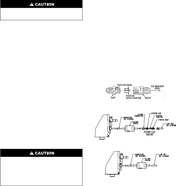
CHECK ACCURATER CONTROL — The correct AccuRater (bypass type) refrigerant control is required for system capacity optimization. An AccuRater device with fieldreplaceable piston (see Fig. 4) is supplied with the outdoor unit. Refer to the AccuRater metering device table in separate indoor unit installation instructions to determine the correct AccuRater piston size required for the condenser/evaporator system being installed.
Piston style as shown in Fig. 4 is shipped with the unit. Do not interchange components between the AccuRater device types. Matching of outdoor unit with indoor unit may require field replacement of piston. Replace piston, if required, before connecting refrigerant lines. See Fig. 4. Piston replacement instructions are included in the indoor unit installation instructions. After system installation is complete, see the Refrigerant Charging section on page 12 to check and/or adjust refrigerant charge.
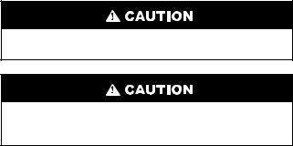
FILTER DRIER — The filter drier must be replaced whenever the refrigeration system is exposed to the atmosphere. See Fig. 4 for filter drier installation.
NOTE: Arrow on AccuRater body points in free flow direction, away from the indoor coil.
38HDF018-036
38HDR018-060
Fig. 4 — AccuRater (Bypass Type) Metering
Device Components
3
Only use factory specified liquid-line filter driers with rated working pressures less than 600 psig.
NOTE: Do not install a suction-line filter drier in liquid line.
MAKE PIPING SWEAT CONNECTIONS — Remove plastic caps from liquid and suction service valves. Use refrigerant grade tubing. Service valves are closed from the factory and are ready for brazing. After wrapping the service valve with a wet cloth, the tubing set can be brazed to the service valve using either silver bearing or non-silver bearing brazing material. Consult local code requirements. Refrigerant tubing and the indoor coil are now ready for leak testing.
NOTE: Unit is shipped with R-410A factory charge indicated on nameplate.
Pass nitrogen or other inert gas through piping while brazing to prevent formation of copper oxide.
To avoid damage while brazing, service valves should be wrapped with a heat-sinking material such as a wet cloth.
When brazing tubing sets to the service valves, a brazing shield MUST be used to prevent damage to the painted unit surface.
PROVIDE SAFETY RELIEF — A fusible plug is located in unit suction line; do not cap this plug. If local code requires additional safety devices, install as directed.
Table 1A — 38HDF018-036 Physical Data
|
UNIT 38HDF |
018 |
|
024 |
|
030 |
|
036 |
NOMINAL CAPACITY (Tons) |
1.5 |
|
2.0 |
|
2.50 |
|
3.0 |
|
OPERATING WEIGHT (lb) |
166 |
|
176 |
|
187 |
|
250 |
|
REFRIGERANT TYPE |
|
|
|
|
R-410A |
|
||
METERING DEVICE |
|
|
AccuRater (Located at Fan Coil) |
|
||||
CHARGE (lb)* |
4.8 |
|
5.3 |
|
5.0 |
|
7.1 |
|
OUTDOOR FAN |
|
|
|
|
|
|
|
|
Rpm/Cfm |
840/1720 |
|
840/1720 |
|
840/1720 |
|
850/1720 |
|
|
|
|
||||||
Diameter (in.) |
18 |
|
18 |
|
18 |
|
24 |
|
No. Blades |
3 |
|
3 |
|
3 |
|
3 |
|
Motor (hp) |
1/8 |
|
1/8 |
|
1/8 |
|
1/4 |
|
OUTDOOR COIL |
|
|
|
|
|
|
|
|
Face Area (sq ft) |
5.82 |
|
7.27 |
|
7.27 |
|
12.1 |
|
|
|
|
||||||
No. Rows |
2 |
|
3 |
|
3 |
|
2 |
|
FPI |
20 |
|
20 |
|
20 |
|
20 |
|
HIGH PRESSURE SWITCH |
|
|
|
|
|
|
|
|
Cut-In (psig) |
420 ± 25 |
|
420 ± 25 |
|
420 ± 25 |
|
420 ± 25 |
|
|
|
|
||||||
Cutout (psig) |
650 ± 10 |
|
650 ± 10 |
|
650 ± 10 |
|
650 ± 10 |
|
LOW PRESSURE SWITCH |
|
|
|
|
|
|
|
|
Cut-In (psig) |
45 ± 25 |
|
45 ± 25 |
|
45 ± 25 |
|
45 ± 25 |
|
|
|
|
||||||
Cutout (psig) |
20 ± 5 |
|
20 ± 5 |
|
20 ± 5 |
|
20 ± 5 |
|
REFRIGERANT LINES |
|
|
|
|
|
|
|
|
Connection Type |
|
|
|
|
Sweat |
|
||
Liquid Line (in.) OD |
3/ |
|
3/ |
|
3/ |
|
3/ |
|
|
|
|
||||||
Vapor Line (in.) OD |
8 |
|
8 |
|
8 |
|
8 |
|
5/8 |
|
5/8 |
|
3/4 |
|
3/4 |
||
Max Length (ft) |
200 |
|
200 |
|
200 |
|
200 |
|
Max Lift (ft) |
65 |
|
65 |
|
65 |
|
65 |
|
Max Drop (ft) |
150 |
|
150 |
|
150 |
|
150 |
|
COMPRESSOR |
|
|
|
|
|
|
|
|
Type |
|
|
|
|
Scroll |
|
||
Model |
ZP16K5E-PFV |
|
ZP21K5E-PFV |
|
ZP25K5E-PFV |
|
ZP34K5P-PFV |
|
|
|
|
||||||
Oil Charge (POE - oz) |
25.0 |
|
25.0 |
|
25.0 |
|
42.0 |
|
Accumulator |
|
|
|
|
Yes |
|
|
|
CONTROLS |
|
|
|
|
|
|
|
|
Fusible Plug (F) |
|
|
|
210 |
|
|
||
Control Voltage† |
|
|
|
|
24 vac |
208/230 v, Single and 3 Phase, |
||
System Voltage |
208/230 v |
|
208/230 v |
|
208/230 v |
|
||
|
|
|
460 v, 3 Phase |
|||||
|
|
|
|
|
|
|
|
|
FINISH |
|
|
|
|
Gray |
|
||
|
LEGEND |
|
|
*Unit shipped with full factory charge. See ARI (Air Conditioning and |
||||
FPI |
— Fins Per Inch |
|
|
Refrigeration Institute) capacity table for proper charge and piston |
||||
|
|
for each fan coil type. |
|
|||||
POE |
— Polyol Ester |
|
|
|
||||
|
|
†24 v and a minimum of 40 va is provided in the fan coil unit. |
||||||
|
|
|
|
|||||
4
Table 1B — 38HDR018-060 Physical Data
|
UNIT 38HDR |
018 |
|
024 |
|
030 |
|
|
036 |
|
|
048 |
|
|
060 |
||||
NOMINAL CAPACITY (Tons) |
1.5 |
|
2.0 |
|
2.50 |
|
|
3.0 |
|
|
4.0 |
|
|
5.0 |
|||||
OPERATING WEIGHT (lb) |
166 |
|
176 |
|
250 |
|
|
250 |
|
|
278 |
|
|
306 |
|||||
REFRIGERANT TYPE |
|
|
|
|
|
|
R-410A |
|
|
|
|
|
|
|
|
||||
METERING DEVICE |
|
|
|
|
|
|
AccuRater (Located at Fan Coil) |
|
|
|
|
|
|
|
|
||||
CHARGE (lb)* |
6.3 |
|
6.5 |
|
10.0 |
|
|
8.9 |
|
|
12.0 |
|
|
12.2 |
|||||
OUTDOOR FAN |
|
|
|
|
|
|
|
|
|
|
|
|
|
|
|
|
|
|
|
Rpm/Cfm |
840/1720 |
|
840/1720 |
|
850/3900 |
|
|
850/3900 |
|
|
850/3900 |
|
|
850/3900 |
|||||
|
|
|
|
|
|||||||||||||||
Diameter (in.) |
18 |
|
18 |
|
24 |
|
|
18 |
|
|
24 |
|
|
24 |
|||||
No. Blades |
3 |
|
3 |
|
3 |
|
|
3 |
|
|
3 |
|
|
3 |
|||||
Motor (hp) |
1/ |
8 |
|
1/ |
8 |
|
1/ |
|
|
1/ |
|
|
1/ |
4 |
|
|
1/ |
4 |
|
|
|
|
|
|
|
4 |
|
|
4 |
|
|
|
|
|
|
||||
OUTDOOR COIL |
|
|
|
|
|
|
|
|
|
|
|
|
|
|
|
|
|
|
|
Face Area (sq ft) |
5.8 |
|
7.3 |
|
12.1 |
|
|
12.1 |
|
|
14.1 |
|
|
14.1 |
|||||
|
|
|
|
|
|||||||||||||||
No. Rows |
2 |
|
3 |
|
2 |
|
|
2 |
|
|
3 |
|
|
3 |
|||||
FPI |
20 |
|
20 |
|
20 |
|
|
20 |
|
|
20 |
|
|
20 |
|||||
HIGH PRESSURE SWITCH |
|
|
|
|
|
|
|
|
|
|
|
|
|
|
|
|
|
|
|
Cut-In (psig) |
420 ± 25 |
|
420 ± 25 |
|
420 ± 25 |
|
|
420 ± 25 |
|
|
420 ± 25 |
|
|
420 ± 25 |
|||||
|
|
|
|
|
|||||||||||||||
Cutout (psig) |
650 ± 10 |
|
650 ± 10 |
|
650 ± 10 |
|
|
650 ± 10 |
|
|
650 ± 10 |
|
|
650 ± 10 |
|||||
LOW PRESSURE SWITCH |
|
|
|
|
|
|
|
|
|
|
|
|
|
|
|
|
|
|
|
Cut-In (psig) |
45 ± 25 |
|
45 ± 25 |
|
45 ± 25 |
|
|
45 ± 25 |
|
|
45 ± 25 |
|
|
45 ± 25 |
|||||
|
|
|
|
|
|||||||||||||||
Cutout (psig) |
20 ± 5 |
|
20 ± 5 |
|
20 ± 5 |
|
|
20 ± 5 |
|
|
20 ± 5 |
|
|
20 ± 5 |
|||||
REFRIGERANT LINES |
|
|
|
|
|
|
|
|
|
|
|
|
|
|
|
|
|
|
|
Connection Type |
|
|
|
|
|
|
|
Sweat |
|
|
|
|
|
|
|
|
|||
Liquid Line (in.) OD |
3/8 |
|
3/8 |
|
3/8 |
|
|
3/8 |
|
|
3/8 |
|
|
3/8 |
|||||
|
|
|
|
|
|||||||||||||||
Vapor Line (in.) OD |
5/8 |
|
5/8 |
|
3/4 |
|
|
3/4 |
|
|
7/8 |
|
|
7/8† |
|||||
Max Length (ft) |
200 |
|
200 |
|
200 |
|
|
200 |
|
|
200 |
|
|
200 |
|||||
Max Lift (ft) |
65 |
|
65 |
|
65 |
|
|
65 |
|
|
65 |
|
|
65 |
|||||
Max Drop (ft) |
150 |
|
150 |
|
150 |
|
|
150 |
|
|
150 |
|
|
150 |
|||||
COMPRESSOR |
|
|
|
|
|
|
|
|
|
|
|
|
|
|
|
|
|
|
|
Type |
|
|
|
|
|
|
|
Scroll |
|
|
|
|
|
|
|
|
|||
Model |
ZP16K5E-PFV |
|
ZP21K5E-PFV |
|
ZP25K5E-PFV |
|
ZPZ9K5E-PFV |
|
ZP42K5E-PFV |
|
ZP51K5E-PFV |
||||||||
|
|
|
|
|
|||||||||||||||
Oil Charge (POE - oz) |
25.0 |
|
25.0 |
|
25.0 |
|
|
25.0 |
|
|
42.0 |
|
|
42.0 |
|||||
Crankcase Heater (watts) |
— |
|
— |
|
40 |
|
|
40 |
|
|
40 |
|
|
40 |
|||||
Accumulator |
|
|
|
|
|
|
|
Yes |
|
|
|
|
|
|
|
|
|||
CONTROLS |
|
|
|
|
|
|
|
|
|
|
|
|
|
|
|
|
|
|
|
Fusible Plug (F) |
|
|
|
|
|
|
|
210 |
|
|
|
|
|
|
|
|
|||
Control Voltage** |
|
|
|
|
|
|
|
24 vac |
|
|
|
|
|
|
|
|
|||
System Voltage |
208/230 v |
|
208/230 v |
|
208/230 v |
|
|
208/230 v, Single and 3 Phase, 460 v, 3 Phase |
|||||||||||
|
|
|
|||||||||||||||||
FINISH |
|
|
|
|
|
|
|
Gray |
|
|
|
|
|
|
|
|
|||
|
LEGEND |
|
|
|
|
|
|
*Unit shipped with full factory charge. See ARI (Air Conditioning |
|||||||||||
FPI |
— Fins Per Inch |
|
|
|
|
|
|
and Refrigeration Institute) capacity table for proper charge and |
|||||||||||
|
|
|
|
|
|
piston for each fan coil type. |
|
|
|
|
|
|
|
|
|||||
POE |
— Polyol Ester |
|
|
|
|
|
|
|
|
|
|
|
|
|
|
||||
|
|
|
|
|
|
†Valve connection size is 7/8 |
inch. Recommended |
line size is |
|||||||||||
|
|
|
|
|
|
|
|
||||||||||||
11/8 inches.
**24 v and a minimum of 40 va is provided in the fan coil unit.
5
 Loading...