


38AKS028-044 Air-Cooled Condensing Units 50/60 Hz
Installation, Start-Up and
Service Instructions
CONTENTS
Page
SAFETY CONSIDERATIONS . . . . . . . . . . . . . . . . . . . 1
BEFORE INSTALLATION . . . . . . . . . . . . . . . . . . . . . 1-3
Rigging . . . . . . . . . . . . . . . . . . . . . . . . . . . . . . . . . . . . . . 1
Placing Unit . . . . . . . . . . . . . . . . . . . . . . . . . . . . . . . . . 3
Mounting Unit . . . . . . . . . . . . . . . . . . . . . . . . . . . . . . . 3
Compressor Mounting . . . . . . . . . . . . . . . . . . . . . . . . 3
INSTALLATION . . . . . . . . . . . . . . . . . . . . . . . . . . . . . 3-12
Refrigerant Piping Connections . . . . . . . . . . . . . . . 3
Liquid Line Solenoid Drop Control . . . . . . . . . . . . 3
Filter Drier and Moisture Indicator . . . . . . . . . . . . 3
Receiver . . . . . . . . . . . . . . . . . . . . . . . . . . . . . . . . . . . . . 4
Piping Procedure . . . . . . . . . . . . . . . . . . . . . . . . . . . . 4
Power Supply . . . . . . . . . . . . . . . . . . . . . . . . . . . . . . . . 6
Power Wiring . . . . . . . . . . . . . . . . . . . . . . . . . . . . . . . . 6
START-UP . . . . . . . . . . . . . . . . . . . . . . . . . . . . . . . . 13-17
Initial Check . . . . . . . . . . . . . . . . . . . . . . . . . . . . . . . . 13
Leak Test and Dehydration . . . . . . . . . . . . . . . . . . 13
Preliminary Charge . . . . . . . . . . . . . . . . . . . . . . . . . . 13
Start Unit . . . . . . . . . . . . . . . . . . . . . . . . . . . . . . . . . . . 13
Charge System . . . . . . . . . . . . . . . . . . . . . . . . . . . . . 13
Operation . . . . . . . . . . . . . . . . . . . . . . . . . . . . . . . . . . . 13
Control Module (CM) . . . . . . . . . . . . . . . . . . . . . . . . 13
Bypass Relay (BPR) . . . . . . . . . . . . . . . . . . . . . . . . . 17
Time-Delay Relay (TDR) . . . . . . . . . . . . . . . . . . . . . 17
Sequence of Operation . . . . . . . . . . . . . . . . . . . . . . 17
Complete Unit Stoppage . . . . . . . . . . . . . . . . . . . . . 17
SAFETY CONSIDERATIONS
Installing, starting up, and servicing air-conditioning equipment can be hazardous due to system pressures, electrical components, and equipment location (roofs, elevated structures, etc.).
Only trained, quali®ed installers and service mechanics should install, start up, and service this equipment (Fig. 1).
Untrained personnel can perform basic maintenance functions such as cleaning coils. All other operations should be performed by trained service personnel.
When working on the equipment, observe precautions in the literature and on tags, stickers, and labels attached to the equipment.
·Follow all safety codes.
·Wear safety glasses and work gloves.
·Keep, quenching cloth and ®re extinguisher nearby when brazing.
·Use care in handling, rigging, and setting bulky equipment.
·See Table 1A or 1B for physical data.
ELECTRIC SHOCK HAZARD
Open all remote disconnects before servicing this equipment.
SERVICE . . . . . . . . . . . . . . . . . . . . . . . . . . . . . . . . . . 17-20 Access for Servicing . . . . . . . . . . . . . . . . . . . . . . . . 17 Fan Adjustment . . . . . . . . . . . . . . . . . . . . . . . . . . . . . 19 Oil Charge . . . . . . . . . . . . . . . . . . . . . . . . . . . . . . . . . . 19
Liquid Shutoff/Charging Valve . . . . . . . . . . . . . . . 19
Capacity Control . . . . . . . . . . . . . . . . . . . . . . . . . . . . 19
Oil Pressure Safety Switch (OPS) . . . . . . . . . . . . 20
Compressor Protection . . . . . . . . . . . . . . . . . . . . . . 20 High-Pressure Switch . . . . . . . . . . . . . . . . . . . . . . . 20 Low-Pressure Switch . . . . . . . . . . . . . . . . . . . . . . . . 20 Winter Start Control . . . . . . . . . . . . . . . . . . . . . . . . . 20 Head Pressure Control . . . . . . . . . . . . . . . . . . . . . . 20
TROUBLESHOOTING . . . . . . . . . . . . . . . . . . . . . . . . 21 START-UP CHECKLIST . . . . . . . . . . . . . . . . . . . . . CL-1
BEFORE INSTALLATION
Rigging Ð Preferred method is with spreader bars from above the unit. Use 2-in. (50 mm) OD pipe or hooks in lifting holes. Rig with 4 cables and spreader bars. All panels must be in place when rigging. See rigging label on unit for details concerning shipping weights, distance between lifting holes, center of gravity, and spreader bar dimensions. See Fig. 2.
If overhead rigging is not possible, place unit on skid or pad for rolling or dragging. When rolling, use minimum of 3 rollers. When dragging, pull the pad. Do not apply force to the unit. When in ®nal position, raise from above to lift unit off pad.
All panels must be in place when rigging.
Manufacturer reserves the right to discontinue, or change at any time, speci®cations or designs without notice and without incurring obligations.
Book |
1 |
|
PC 111 |
Catalog No. 533-820 |
Printed in U.S.A. |
Form 38A-5SI |
Pg 1 |
7-94 |
Replaces: 38AK-3SI |
Tab |
3a |
|
|
|
|
|
|
|
|
|
|
|
|
|
|
|
|
|
|
Table 1A Ð Physical Data Ð English
UNIT 38AKS |
028 |
|
034 |
|
044 |
COMPRESSOR |
|
Reciprocating Semi-Hermetic |
|
||
No. ...Type |
1...06E9265 |
|
1...06E9275 |
|
1...06E9299 |
No. Cyls (ea)...Speed, Rpm (60/50 Hz) |
|
|
6...1750/1460 |
|
|
Capacity Steps |
|
3 |
|
|
|
Oil Charge*, Pt |
20.0 |
|
20.0 |
|
19.0 |
Oil Pressure Switch (psi) |
|
|
|
|
|
Set Points Ð Cutout |
|
|
6 6 2 |
|
|
Differential Ð Cut-in |
|
|
14 Max. |
|
|
Crankcase Heater (watts) |
|
180 |
|
|
|
Protection |
|
|
See Note |
|
|
Capacity Control (Psig) |
|
Suction Pressure Unloader(s) |
|
||
No. 1 |
|
|
Unloader Settings |
|
|
Load |
76 |
|
76 |
|
76 |
Unload |
58 |
|
58 |
|
58 |
No. 2 |
|
|
Unloader Settings |
|
|
Load |
78 |
|
78 |
|
78 |
Unload |
60 |
|
60 |
|
60 |
REFRIGERANT CHARGE, R-22 |
|
|
|
|
|
Approximate lb |
30.5 |
|
43.5 |
|
65 |
COIL STORAGE |
|
|
|
|
|
(at 125 F liquid temperature |
37.7 |
|
56.6 |
|
84.4 |
and 80% full), lb |
|
|
|||
|
|
|
|
|
|
CONDENSER FANS, Type |
|
Propeller Type, Direct Driven |
|
||
No. ...Diameter, in. |
|
2...30 |
|
3...30 |
|
Total Air¯ow, Cfm |
|
15,700 |
|
23,700 |
|
Speed, Rpm 60/50 Hz |
|
1140/950 |
|
|
|
CONDENSER COIL, Type |
|
|
Horizontal Plate Fin |
|
|
Rows...Fins/in. |
2...19 |
|
3...17 |
|
3...17 |
Total Face Area, sq ft |
39.2 |
|
39.2 |
|
58.4 |
|
|
|
|
|
|
*See Service, Oil Charge, for Carrier-approved oil. NOTE: Circuit breaker is in main power circuit.
Table 1B Ð Physical Data Ð SI
UNIT 38AKS |
028 |
|
034 |
|
044 |
COMPRESSOR |
|
Reciprocating Semi-Hermetic |
|
||
No. ...Type |
1...06E9265 |
|
1...06E9275 |
|
1...06E9299 |
No. Cyls (ea)...Speed, R/s (60/50 Hz) |
|
|
6...29.2/24.3 |
|
|
Capacity Steps |
|
3 |
|
|
|
Oil Charge*, L |
9.4 |
|
9.4 |
|
9.0 |
Oil Pressure Switch (kPa) |
|
|
|
|
|
Set Points Ð Cutout |
|
|
41.4 6 13.8 |
|
|
Differential Ð Cut-in |
|
|
96.5 Max. |
|
|
Crankcase Heater (watts) |
|
180 |
|
|
|
Protection |
|
|
See Note |
|
|
Capacity Control (kPa) |
|
Suction Pressure Unloader(s) |
|
||
No. 1 |
|
|
Unloader Settings |
|
|
Load |
524 |
|
524 |
|
524 |
Unload |
400 |
|
400 |
|
400 |
No. 2 |
|
|
Unloader Settings |
|
|
Load |
538 |
|
538 |
|
538 |
Unload |
414 |
|
414 |
|
414 |
REFRIGERANT CHARGE, R-22 |
|
|
|
|
|
Approximate, kg |
13.8 |
|
19.7 |
|
29.5 |
COIL STORAGE |
|
|
|
|
|
(at 52 C liquid temperature |
17.1 |
|
25.7 |
|
38.3 |
and 80% full), kg |
|
|
|||
|
|
|
|
|
|
CONDENSER FANS, Type |
|
|
Propeller Type, Direct Driven |
|
|
No. ...Diameter, mm |
|
2...762 |
|
3...762 |
|
Total Air¯ow, L/s |
|
7,400 |
|
11,200 |
|
Speed, R/s (60/50 Hz) |
|
19.0/15.8 |
|
19.0/15.8 |
|
CONDENSER COIL, Type |
|
|
Horizontal Plate Fin |
|
|
Rows...Fins/mm |
2...1.34 |
|
3...1.49 |
|
3...1.49 |
Total Face Area, sq m |
3.64 |
|
3.64 |
|
5.43 |
|
|
|
|
|
|
*See Service, Oil Charge, for Carrier-approved oil. NOTE: Circuit breaker is in main power circuit.
2
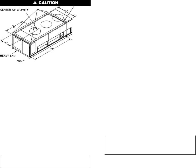
Fig. 1 Ð 38AKS Units
NOTES:
1.Use 2 in. OD (50 mm) pipe or hooks in lifting holes.
2.Rig with 4 cables and spread with 2 ``D'' long and two ``A'' long 2 x 4's in. (50 x 100 mm) or equal.
3.Run the rigging cables to a central suspension point so that the angle from the horizontal is not less than 45 degrees.
All panels must be in place when rigging.
|
MAX SHIP. |
LIFTING |
CENTER OF GRAVITY |
|
|
||||||
UNIT |
HOLES |
|
|
|
|
``D'' |
|||||
38AKS |
WT |
|
``A'' |
``B'' |
``C'' |
|
|
||||
|
|
|
|
|
|||||||
|
Lb |
Kg |
in. |
|
mm |
in. |
mm |
in. |
mm |
in. |
mm |
028 |
1924 |
872 |
81 |
|
2057 |
43.0 |
1092 |
28.0 |
711 |
73.5 |
1867 |
034 |
2115 |
960 |
81 |
|
2057 |
43.0 |
1092 |
28.0 |
711 |
73.5 |
1867 |
044 |
2797 |
1207 |
99 |
|
2515 |
49.0 |
1245 |
30.5 |
775 |
73.5 |
1867 |
|
|
|
|
|
|
|
|
|
|
|
|
Fig. 2 Ð Rigging with Spreader Bars (Field Supplied)
Placing Unit Ð There must be 4 ft (1220 mm) for service on all sides of unit, and a minimum of 8 ft (2440 mm) clear air space above unit. For multiple units, allow 8 ft (2440 mm) separation between units for air¯ow and service.
Mounting Unit Ð When unit is in proper location, use of mounting holes in base rails is recommended for securing unit to supporting structure or for mounting unit on vibration isolators, if required. Fasteners for mounting unit are ®eld supplied. Be sure to mount unit level to ensure proper oil return to compressors.
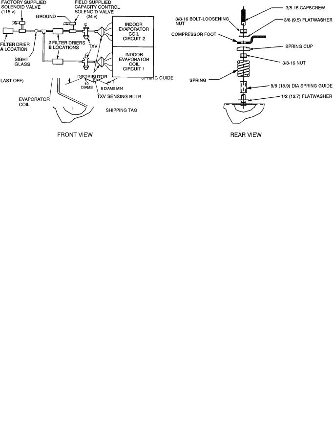
Compressor Mounting Ð As shipped, compressor is held down by 4 bolts. After unit is installed loosen each bolt using nut indicated in Fig. 3 until ¯atwasher (3¤8 in. [9.5 mm]) can be moved with ®nger pressure.
INSTALLATION
Refrigerant Piping Connections Ð Line sizes depend on length of piping required between condensing unit and evaporator. See Table 2A or 2B. It is important to consider liquid lift and compressor oil return. Refer to Part 3 of Carrier System Design Manual for line sizing information, and Fig. 4 for recommended piping details.
Liquid Line Solenoid Drop Control Ð The factorysupplied solenoid valve must be installed at the indoor unit (fan coil) per Fig. 5, and wired per wiring label found on unit. The solenoid assures that system refrigerant is in the high-pressure side (condenser and liquid line) of the system during the off cycle. Refrigerant migration is minimized.
Factory-supplied liquid line solenoid valve connecting sizes are 7¤8-in. (22.2 mm) ODF for inlet and 7¤8-in. (22.2 mm) ODM for outlet.
Failure to properly install liquid line solenoid at the indoor unit as described, without Carrier authorization, may VOID warranty.
Filter Drier and Moisture Indicator Ð Every unit should have a ®lter drier and a sight glass (moisture indicator) ®eld installed. Select the ®lter drier for maximum unit capacity and minimum pressure drop. Figure 5 shows recommended locations of ®lter drier(s) and sight glass. Complete the refrigerant piping from the evaporator to the condenser before opening the liquid and suction lines at the condensing unit. One ®lter drier may be installed at location A in Fig. 5, or 2 ®lter driers may be installed at locations B.
3
NOTE: All dimensions are in inches (mm).
Fig. 3 Ð Compressor Mounting
TXV Ð Thermostatic Expansion Valve
NOTES:
1.Suction line is connected to coil on same side as the entering air.
2.Lower section is ®rst on and last off.
3.For more complete piping information, refer to Carrier System Design Manual, Part 3.
Fig. 4 Ð Suction Line Piping to Unit with 2 Section Coil Split
TXV Ð Thermostatic Expansion Valve
Fig. 5 Ð Liquid Line Solenoid Valve, Filter Drier(s) and Sight Glass Locations
Receiver Ð No receiver is provided with the unit; it is recommended that one not be used.
Piping Procedure Ð Do not remove run-around pipe from suction and liquid line stubs until piping connections are ready to be made. Pass nitrogen or other inert gas through piping while brazing, to prevent formation of copper oxide.
Install ®eld-supplied thermostatic expansion valve (TXV) in liquid line ahead of each evaporator section. For 2-stage cooling, the ®eld-supplied capacity control solenoid used must be wired to be opened by control from a 2-stage thermostat.
SUCTION PIPING AT EVAPORATOR AND TXV BULB LOCATION (See Fig. 5) Ð The purpose of these recommendations is to achieve good mixing of the refrigerant leaving the evaporator suction header for proper sensing by the TXV bulb.
1.A minimum of two 90° elbows must be installed upstream of the expansion valve bulb location.
2.The TXV sensing bulb should be located on a vertical riser where possible. If a horizontal location is necessary, secure the bulb at approximately the 4 o'clock position.
3.Size the suction line from the evaporator through the riser for high velocity. Enter the suction pipe sizing charts in the Carrier System Design Manual at design tons and equivalent length (for 2° F [1.1° C] loss). If reading falls between 2 sizes on chart, choose the smaller pipe size.
Suction piping for the high velocity section should be selected for about 0.5° F (0.3° C) friction loss. If a 2° F (1.1° C) loss is allowed for the entire suction line, 1.5° F (0.8° C) is left for the balance of the suction line, and it should be sized on that basis. Check that the high-velocity sizing is adequate for oil return up the riser.
If an oil return connection at the bottom of this suction header is supplied with an evaporator, this connection must be teed-in ahead of ®rst mixing elbow. When the compressor is below the evaporator, the riser at the evaporator does not have to extend as high as the top level. After a 15-diameter riser has been provided, the suction line may elbow down immediately.
SAFETY RELIEF Ð A fusible plug is located on unit liquid line before the liquid valve.
4
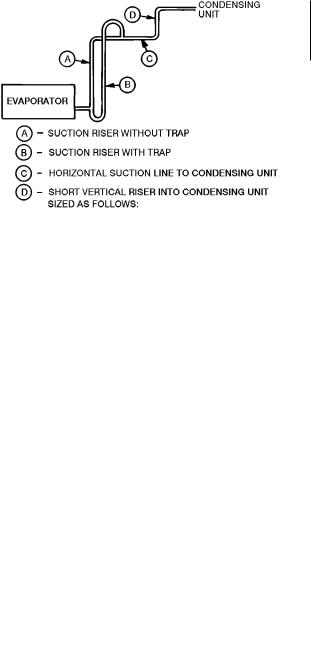
Table 2A Ð Refrigerant Piping Sizes Ð 60 Hz
SINGLE SUCTION RISERS
UNIT |
|
|
|
LENGTH OF INTERCONNECTING PIPING, FT (M) |
|
|
|
|||||
16-25 (4.9-7.6) |
26-50 (7.9-15.2) |
51-75 (15.5-22.8) |
76-100 (23.2-30.5) |
101-200 (30.8-60.9) |
||||||||
38AKS |
||||||||||||
|
L |
S |
L |
S |
L |
S |
L |
|
S |
L |
S |
|
028 |
7¤8 |
15¤8 |
7¤8 |
21¤8* |
7¤8 |
21¤8* |
7¤8 |
|
21¤8* |
7¤8 |
21¤8* |
|
034 |
7¤8 |
21¤8 |
7¤8 |
21¤8 |
7¤8 |
21¤8 |
11¤8 |
|
21¤8 |
11¤8 |
25¤8* |
|
044 |
7¤8 |
21¤8 |
7¤8 |
21¤8 |
11¤8 |
25¤8* |
11¤8 |
|
25¤8* |
11¤8 |
25¤8* |
|
L Ð |
Liquid Line |
S Ð |
Suction Line |
*IMPORTANT Ð Requires a double suction riser, if evaporator is below condensing unit. See table below. NOTE: Liquid and suction line sizes are OD (in.) Equivalent sizes in mm are listed below.
DOUBLE SUCTION RISERS Ð 60 Hz
UNIT |
|
|
|
|
|
LENGTH OF INTERCONNECTING PIPING, FT (M) |
|
|
|
||||||||
|
26-50 (7.9-15.2) |
|
51-75 (15.5-22.8) |
|
76-100 (23.2.-30.5) |
|
101-200 (30.8-60.9) |
||||||||||
38AKS |
|
|
|
|
|||||||||||||
|
A |
|
B |
C |
A |
|
|
B |
|
C |
A |
B |
|
C |
A |
B |
C |
028 |
13¤8 |
|
15¤8 |
21¤8 |
13¤8 |
|
|
15¤8 |
|
21¤8 |
13¤8 |
15¤8 |
|
21¤8 |
13¤8 |
15¤8 |
21¤8 |
034 |
Ð |
|
Ð |
Ð |
Ð |
|
Ð |
Ð |
Ð |
Ð |
Ð |
|
1 |
5¤8 |
21¤8 |
25¤8 |
|
044 |
Ð |
|
Ð |
Ð |
1 5¤8 |
|
|
21¤8 |
|
25¤8 |
15¤8 |
21¤8 |
|
25¤8 |
15¤8 |
21¤8 |
25¤8 |
NOTE: A, B, C dimensions relate to reference diagram.
Table 2B Ð Refrigerant Piping Sizes Ð 50 Hz
SINGLE SUCTION RISERS
UNIT |
|
|
|
LENGTH OF INTERCONNECTING PIPING, FT (M) |
|
|
|
|||||
16-25 (4.9-7.6) |
26-50 (7.9-15.2) |
51-75 (15.5-22.8) |
76-100 (23.2-30.5) |
101-200 (30.8-60.9) |
||||||||
38AKS |
||||||||||||
|
L |
S |
L |
S |
L |
S |
L |
|
S |
L |
S |
|
028 |
7¤8 |
15¤8 |
7¤8 |
21¤8* |
7¤8 |
21¤8* |
7¤8 |
|
21¤8* |
7¤8 |
21¤8* |
|
034 |
7¤8 |
21¤8² |
7¤8 |
21¤8* |
7¤8 |
21¤8* |
11¤8 |
|
25¤8* |
11¤8 |
25¤8* |
|
044 |
7¤8 |
21¤8 |
7¤8 |
21¤8 |
11¤8 |
25¤8* |
11¤8 |
|
25¤8* |
11¤8 |
25¤8* |
|
L Ð |
Liquid Line |
S Ð |
Suction Line |
*IMPORTANT Ð Requires a double suction riser, if evaporator is below condensing unit. See table below. ²For riser, use 1 5¤8 OD inches.
NOTE: Liquid and suction line sizes are OD (in.) Equivalent sizes in mm are listed below.
DOUBLE SUCTION RISERS Ð 50 Hz
UNIT |
|
|
|
|
|
LENGTH OF INTERCONNECTING PIPING, FT (M) |
|
|
|
|||||||
|
26-50 (7.9-15.2) |
|
51-75 (15.5-22.8) |
|
76-100 (23.2.-30.5) |
|
101-200 (30.8-60.9) |
|||||||||
38AKS |
|
|
|
|
||||||||||||
|
A |
|
B |
C |
A |
|
B |
|
C |
A |
B |
|
C |
A |
B |
C |
028 |
13¤8 |
|
15¤8 |
21¤8 |
13¤8 |
|
15¤8 |
|
21¤8 |
13¤8 |
15¤8 |
|
21¤8 |
13¤8 |
15¤8 |
21¤8 |
034 |
15¤8 |
|
15¤8 |
21¤8 |
15¤8 |
|
15¤8 |
|
21¤8 |
15¤8 |
15¤8 |
|
21¤8 |
15¤8 |
21¤8 |
25¤8 |
044 |
Ð |
|
Ð |
Ð |
1 5¤8 |
|
21¤8 |
|
25¤8 |
15¤8 |
21¤8 |
|
25¤8 |
15¤8 |
21¤8 |
25¤8 |
NOTE: A, B, C dimensions relate to reference diagram.
MAXIMUM LIQUID LIFT
UNIT 38AKS |
|
60 Hz |
|
50 Hz |
||
Ft |
|
M |
Ft |
|
M |
|
|
|
|
||||
028 |
76 |
|
23 |
66 |
|
20 |
034 |
67 |
|
20 |
60 |
|
18 |
044 |
76 |
|
23 |
66 |
|
20 |
EQUIVALENT SIZES IN MM
in. |
mm |
7¤8 |
22.2 |
11¤8 |
28.6 |
13¤8 |
34.9 |
15¤8 |
41.3 |
21¤8 |
54.0 |
25¤8 |
66.7 |
Unit Size |
Dimension Ð in. (mm) |
|
028 |
15¤8 |
(41.3) |
034 |
21¤8 |
(54.0) |
044 |
21¤8 |
(54.0) |
5
Power Supply Ð Electrical characteristics of available power supply must agree with unit nameplate rating. Supply voltage must be within limits shown in Table 3.
IMPORTANT: Operating unit on improper supply voltage, or with excessive phase imbalance, constitutes abuse and may affect Carrier warranty. See Unbalanced 3-Phase Supply Voltage, page 7.
Power Wiring Ð All power wiring must comply with applicable local and national codes. Install ®eld-supplied branch circuit fused disconnect(s) per NEC (National Electrical Code, U.S.A.) of a type that can be locked OFF or OPEN. Disconnect(s) must be within sight from and readily accessible from unit in compliance with NEC Article 440-14.
GENERAL WIRING NOTES
1.A crankcase heater is wired in the control circuit so it is always operable as long as power supply disconnect is on, even if any safety device is open or unit stop-start switch is off. It is protected by a 5-amp circuit breaker in control power.
2.The power circuit ®eld supply disconnect should never be open except when unit is being serviced or is to be down for a prolonged period. When operation is resumed, crankcase heater should be energized for 24 hours before startup. If unit is to be shut down for a prolonged period, it is recommended that the suction and discharge valves be
closed to prevent an excessive accumulation of refrigerant in the compressor oil.
3.Power entry is one end only.
4.Maximum ®eld wire sizes allowed by lugs on terminal block are:
UNIT |
V-Ph-Hz |
WIRE |
|
38AKS |
SIZE* |
||
|
|||
028 |
208/230-3-60 |
|
|
034 |
208/230-3-60 |
|
|
230-3-50 |
350 kcmil |
||
|
|||
044 |
208/230-3-60 |
|
|
230-3-50 |
|
||
|
|
||
LEGEND |
|
|
AWG Ð American Wire Gage kcmil Ð Thousand Circular Mils
*All other units use 2/0 AWG (67.4 mm2).
5.Terminals for ®eld power supply are suitable for copper, copper-clad aluminum, or aluminum conductors. Insulation must be rated 167 F (75 C) minimum.
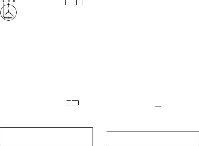
CONDENSER FANS Ð The fans must rotate counterclockwise when viewed from above. If necessary, correct direction of fan rotation by interchanging any 2 power input wires at disconnect switch. Affix crankcase heater decal (located in installer's packet) to unit disconnect switch.
Table 3 Ð Electrical Data
60 HZ
|
UNIT |
|
|
UNIT |
|
|
|
|
COMPRESSOR |
FAN MOTORS |
||||
|
Volts |
Supplied* |
|
|
|
MOCP |
|
|
|
|
|
|||
38AKS |
|
MCA |
|
ICF |
RLA |
LRA |
FLA (ea) |
Qty |
||||||
3 Ph, 60 Hz |
Min. |
Max. |
|
|
(Fuse) |
|||||||||
|
|
|
|
|
|
|
|
|
|
|
||||
|
|
500 |
208/230 |
187 |
254 |
|
124.6 |
|
200 |
452.2 |
89.8 |
446 |
6.2 |
2 |
028 |
|
200 |
380 |
342 |
418 |
|
64.7 |
|
110 |
250.9 |
45.5 |
247 |
3.9 |
2 |
|
600 |
460 |
414 |
508 |
|
60.7 |
|
100 |
226.1 |
43.6 |
223 |
3.1 |
2 |
|
|
|
|
|
|||||||||||
|
|
100 |
575 |
518 |
632 |
|
52.5 |
|
80 |
167.4 |
36.5 |
164 |
3.4 |
2 |
|
|
500 |
208/230 |
187 |
254 |
|
145.5 |
|
250 |
512.2 |
106.5 |
506 |
6.2 |
2 |
034 |
|
200 |
380 |
342 |
418 |
|
72.5 |
|
125 |
283.9 |
52.6 |
280 |
3.9 |
2 |
|
600 |
460 |
414 |
508 |
|
68.7 |
|
110 |
256.1 |
50.0 |
253 |
3.1 |
2 |
|
|
|
|
|
|||||||||||
|
|
100 |
575 |
518 |
632 |
|
54.9 |
|
90 |
179.4 |
38.5 |
176 |
3.4 |
2 |
|
|
500 |
230 |
187 |
254 |
|
203.0 |
|
350 |
702.4 |
147.5 |
690 |
6.2 |
3 |
044 |
|
200 |
380 |
342 |
418 |
|
111.1 |
|
175 |
389.8 |
79.5 |
382 |
3.9 |
3 |
|
600 |
460 |
414 |
508 |
|
91.0 |
|
150 |
351.2 |
65.4 |
345 |
3.1 |
3 |
|
|
|
|
|
|||||||||||
|
|
100 |
575 |
518 |
632 |
|
81.5 |
|
125 |
282.8 |
57.1 |
276 |
3.4 |
3 |
|
|
|
|
|
|
|
|
50 HZ |
|
|
|
|
|
|
|
|
|
|
|
|
|
|
|
|
|
|
|||
|
UNIT |
|
|
UNIT |
|
|
|
|
COMPRESSOR |
FAN MOTORS |
||||
|
Volts |
Supplied* |
|
|
|
MOCP |
|
|
|
|
|
|||
38AKS |
|
MCA |
|
ICF |
RLA |
LRA |
FLA (ea) |
Qty |
||||||
3 Ph, 50 Hz |
Min. |
Max. |
|
|
(Fuse) |
|||||||||
|
|
|
|
|
|
|
|
|
|
|
||||
|
|
800 |
230 |
198 |
254 |
|
109.0 |
|
175 |
348.4 |
76.9 |
342 |
6.4 |
2 |
028 |
|
300 |
346 |
311 |
380 |
|
64.9 |
|
100 |
263.4 |
44.9 |
259 |
4.4 |
2 |
|
|
900 |
400 |
342 |
400 |
|
60.5 |
|
100 |
226.0 |
43.6 |
223 |
3.0 |
2 |
|
|
800 |
230 |
198 |
254 |
|
120.2 |
|
200 |
372.4 |
85.9 |
366 |
6.4 |
2 |
034 |
|
300 |
346 |
311 |
380 |
|
76.1 |
|
125 |
298.4 |
53.9 |
294 |
4.4 |
2 |
|
|
900 |
400 |
342 |
400 |
|
68.5 |
|
110 |
256.0 |
50.0 |
253 |
3.0 |
2 |
|
|
800 |
230 |
198 |
254 |
|
150.6 |
|
250 |
557.8 |
105.1 |
545 |
6.4 |
3 |
044 |
|
300 |
346 |
311 |
380 |
|
112.6 |
|
175 |
408.8 |
79.5 |
400 |
4.4 |
3 |
|
|
900 |
400 |
342 |
400 |
|
90.8 |
|
150 |
351.0 |
65.4 |
345 |
3.0 |
3 |
|
LEGEND |
CSA |
Ð Canadian Standards Association |
FLA |
Ð Full Load Amps |
ICF |
Ð Maximum Instantaneous Current Flow during starting (the point |
|
in the starting sequence where the sum of the LRA for the start- |
|
ing compressor, plus the total FLA for all running fan motors is |
|
maximum). |
LRA |
Ð Locked Rotor Amps |
MCA |
Ð Minimum Circuit Amps (complies with National |
|
Electrical Code [NEC, U.S.A.], Section 430-24) |
MOCP Ð Maximum Overcurrent Protection |
|
RLA |
Ð Rated Load Amps |
UL |
Ð Underwriters' Laboratories |
*Units are suitable for use on electrical systems where voltage supplied to unit terminals is not below or above listed minimum and maximum limits.
6
FIELD CONNECTIONS
1.Main Power Ð Bring wires from the fused disconnect switch through hole in bottom rail of unit to control box
(Fig. 6 and 7) and connect terminals 11 , 12 , and
13 line side of terminal block TB1 (see Fig. 8 and 9A
or 9B). To comply with NEC Article 440-14, the disconnect must be located within sight from and readily accessible from unit.
2.24-v Control Power Ð Units have single point power connections. Control circuit is directly connected internally to unit. Maximum 24-v control circuit is 3 amps.
NOTE: Wire runs use the following insulated wire:
LENGTH |
INSULATED WIRE SIZE* |
||
AWG |
mm2 |
||
|
|||
0-50 |
18 |
0.82 |
|
50-75 |
16 |
1.30 |
|
Over 75 |
14 |
2.08 |
|
|
|
|
|
AWG Ð American Wire Gage *35 C minimum.
3.Control Circuit Interlock Ð An air¯ow switch may be installed in the indoor air handler to prevent unit from running when indoor air is not ¯owing. This switch (no. HR81JE001) is available from Service Parts Center, or equivalent can be ®eld supplied. This should be electrically interlocked in the control circuit, between thermo-
stat TC1 (stage 1, cooling) and terminal 2 
 Y1 on TB3.
See Fig. 8 for typical ®eld wiring. This is in the 24-v circuit. Wires must be run in conduit with ground wire.
4.Transformer Connections Ð See unit wiring label diagram, notes 1 and 2, located behind compressor compartment end access door.
IMPORTANT: Ensure power to the crankcase heater is always on (except when servicing the unit). If circuit breaker inside unit shuts down the compressor, crankcase heater remains on.
UNBALANCED 3-PHASE SUPPLY VOLTAGE Ð Never operate a motor where a phase imbalance in supply voltage is greater than 2%. Use the following formula to determine the percent voltage imbalance:
% Voltage Imbalance
= 100 x |
max voltage deviation from average voltage |
|
|
average voltage |
|
Example: Supply voltage is 240-3-60.
AB = 243 v
BC = 236 v
AC = 238 v
243 + 236 + 238
Average Voltage =
3
= 239 volts
Determine maximum deviation from average voltage:
(AB) 243 − 23 9 = 4 v (BC) 239 − 23 6 = 3 v (AC) 239 − 23 8 = 1 v
Maximum deviation is 4 v. Determine percent voltage imbalance:
4
% Voltage Imbalance = 100 x
239
= 1.7%
This amount of phase imbalance is satisfactory as it is below the maximum allowable 2%.
IMPORTANT: Contact your local electric utility company immediately if the supply voltage phase imbalance is more than 2%.
7

LEGEND
NEC Ð National Electrical Code
VAV Ð Variable Air Volume
NOTES:
1.There must be minimum (2440 mm) 8 ft. clear air space above unit.
2.The approximate operating weight of the unit is:
50 AND 60 HZ
UNIT |
WT |
WT |
|
(Lb) |
(Kg) |
||
|
|||
38AKS028 |
1650 |
748 |
|
38AKS028C |
1804 |
818 |
|
38AKS034 |
1803 |
818 |
|
38AKS034C |
2009 |
911 |
|
|
|
|
3.A ``C'' in the model number indicates unit has factory-installed copper coil.
Fig. 6 Ð Dimensional Drawing, 38AKS028,034
8
 Loading...