


Single Duct Air Terminal Zone Controller
VAV Fan Terminal Zone Controller
Secondary Terminal Zone Controller
Installation, Start-Up and
Configuration Instructions
Part Numbers 33ZCFANTRM, 33ZCVAVTRM, 33ZCSECTRM
CONTENTS
Page
SAFETY CONSIDERATIONS . . . . . . . . . . . . . . . . . . . . . . 1
GENERAL . . . . . . . . . . . . . . . . . . . . . . . . . . . . . . . . . . . . . . . . 2
INSTALLATION . . . . . . . . . . . . . . . . . . . . . . . . . . . . . . . . 2-29
General . . . . . . . . . . . . . . . . . . . . . . . . . . . . . . . . . . . . . . . . . . 2
Zone Controller Hardware . . . . . . . . . . . . . . . . . . . . . . . . 2
Field-Supplied Hardware . . . . . . . . . . . . . . . . . . . . . . . . . 2
•SPACE TEMPERATURE SENSOR
•PRIMARY AIR TEMPERATURE SENSOR
•SUPPLY AIR TEMPERATURE (SAT) SENSOR
•RELATIVE HUMIDITY SENSOR
•INDOOR AIR QUALITY (CO2) SENSOR
Mount Zone Controller . . . . . . . . . . . . . . . . . . . . . . . . . . . 4
•LOCATION
•MOUNTING
Connect the Power Transformer. . . . . . . . . . . . . . . . . . 7
Connect Airflow Pickups . . . . . . . . . . . . . . . . . . . . . . . . . 7
Install Sensors . . . . . . . . . . . . . . . . . . . . . . . . . . . . . . . . . . 19
•SPACE TEMPERATURE SENSOR INSTALLATION
•PRIMARY AIR TEMPERATURE SENSOR INSTALLATION
•SUPPLY AIR TEMPERATURE (SAT) SENSOR INSTALLATION
•INDOOR AIR QUALITY SENSOR INSTALLATION
•HUMIDITY SENSOR (WALL-MOUNTED) INSTALLATION
Remote Occupancy Contact. . . . . . . . . . . . . . . . . . . . . 26
Connect the Outputs . . . . . . . . . . . . . . . . . . . . . . . . . . . . 26
Modulating Baseboard Hydronic Heating . . . . . . . . 26
Connect the CCN Communication Bus . . . . . . . . . . 26
•COMMUNICATION BUS WIRE SPECIFICATIONS
•CONNECTION TO THE COMMUNICATION BUS
START-UP . . . . . . . . . . . . . . . . . . . . . . . . . . . . . . . . . . . . 29-31
Perform System Check-Out . . . . . . . . . . . . . . . . . . . . . 29
Network Addressing. . . . . . . . . . . . . . . . . . . . . . . . . . . . . 30
Initial Operation and Test. . . . . . . . . . . . . . . . . . . . . . . . 30
Airflow Check . . . . . . . . . . . . . . . . . . . . . . . . . . . . . . . . . . . 30
Fan and Heat Configuration and Test. . . . . . . . . . . . 30
CONFIGURATION . . . . . . . . . . . . . . . . . . . . . . . . . . . . 31-50
Points Display Screen . . . . . . . . . . . . . . . . . . . . . . . . . . . 31
Modify Controller Configuration. . . . . . . . . . . . . . . . . 32
•ALARM LIMIT CONFIGURATION SCREEN
•CONTROLLER IDENTIFICATION SCREEN
•HOLIDAY CONFIGURATION SCREENS
•LINKAGE COORDINATOR CONFIGURATION SCREEN
•OCCUPANCY CONFIGURATION SCREEN
•SET POINT SCREEN
Service Configuration Selection Screen. . . . . . . . . 37
•AIRFLOW SERVICE CONFIGURATION SCREEN
•TERMINAL SERVICE CONFIGURATION SCREEN
•OPTIONS SERVICE CONFIGURATION SCREEN
•SECONDARY DAMPER SERVICE
CONFIGURATION SCREEN
Maintenance Table Menu Screen . . . . . . . . . . . . . . . . 43
•LINKAGE MAINTENANCE TABLE
•OCCUPANCY MAINTENANCE TABLE
•ZONE AIR BALANCE/COMMISSIONING TABLE
•ZONE MAINTENANCE TABLE
SAFETY CONSIDERATIONS
SAFETY NOTE
Air-handling equipment will provide safe and reliable service when operated within design specifications. The equipment should be operated and serviced only by authorized personnel who have a thorough knowledge of system operation, safety devices and emergency procedures.
Good judgement should be used in applying any manufacturer’s instructions to avoid injury to personnel or damage to equipment and property.
Disconnect all power to the unit before performing maintenance or service. Unit may automatically start if power is not disconnected. Electrical shock and personal injury could result.
If it is necessary to remove and dispose of mercury contactors in electric heat section, follow all local, state, and federal laws regarding disposal of equipment containing hazardous materials.
Manufacturer reserves the right to discontinue, or change at any time, specifications or designs without notice and without incurring obligations.
Book |
1 |
4 |
PC 111 |
Catalog No. 533-355 |
Printed in U.S.A. |
Form 33ZC-1SI |
Pg 1 |
303 |
11-99 |
Replaces: New |
Tab |
11a |
13a |
|
|
|
|
|
|
|
|
|
|
|
|
|
|
|
|
|
|
|
GENERAL
The zone controller is a single duct, fan powered, Variable Air Volume (VAV) terminal control with a factory-integrated controller and actuator. The zone controller maintains precise temperature control in the space by operating the terminal fan and regulating the flow of conditioned air into the space. Buildings with diverse loading conditions can be supported by controlling reheat or supplemental heat.
The VAV Fan Terminal Zone Controller (33ZCFANTRM) provides dedicated control functions for series fan or parallel fan powered terminals, single duct terminals with 3 stages of heat, or as a primary controller for dual duct or zone pressure control applications.
The Single Duct Air Terminal Zone Controller (33ZCVAVTRM) provides dedicated control functions for single duct terminals with modulating heat or up to 2 stages of heat.
When the VAV Fan Terminal Zone Controller is used in conjunction with a secondary terminal and the 33ZCSECTRM secondary terminal zone controller, either dual duct or zone pressurization applications can be supported.
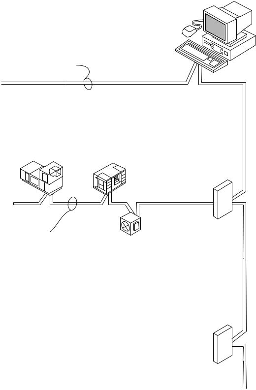
Carrier’s Linkage system is an integrated combination of Carrier Comfort Network (CCN) controllers for use with Single Duct air terminals and VAV Fan Powered terminals. The Single Duct air terminal and VAV Fan terminal zone controllers are part of the Carrier ComfortID system.
Devices manufactured by Carrier which have Product Integrated Controls on the same communication bus as the zone controller, air handlers (such as the 39L,T), or large rooftop units do not require an external controller to function as part of a Carrier linkage system. These air handlers or large rooftop units feature factory-installed Product Integrated Control (PIC) controllers that are directly compatible with the system. Consult your local Carrier representative for the complete list of compatible air handlers. The Comfort System AirManager (CSAM) or the CC6400 supports linkage for non-Carrier devices or air handlers. Figure 1 shows an example of a Carrier linkage system.
INSTALLATION
General — The zone controller is a microprocessor-based direct digital control (DDC) controller for variable air volume (VAV) air terminals. It can be retrofitted on units manufactured by Carrier or other manufacturers to provide pressureindependent VAV control.
Each zone controller has the ability to function as a linkage coordinator for systems with up to 128 zones. As a linkage coordinator, a zone controller will retrieve and provide system information to the air handling equipment and other zone controllers. A zone controller can function as a stand alone device by installing a primary supply air sensor.
The zone controller monitors differential pressure from an airflow pickup (or a pair of pickups) mounted on the terminal box. It compares the resulting signal to an airflow set point in order to provide pressure-independent control of the air passing through the terminal.
The zone controller is connected to a wall-mounted, fieldsupplied, space temperature sensor (SPT) in order to monitor zone temperature changes and satisfy zone demand.
On stand-alone applications or applications with heat, the zone controller must be connected to a field-supplied supply air temperature (SAT) sensor to monitor the temperature of the air delivered by the air terminal.
Carrier’s Network Service Tool can be connected to the system at the SPT sensor if CCN communication wiring is run to
the SPT sensor. The Network Service Tool can be used to adjust set points, set operating parameters, and fully configure the zone controller or any device on the system.
Zone Controller Hardware — The zone controller consists of the following hardware:
•terminal control module
•torque-limiting damper actuator
•airflow transducer (velocity sensor)
•plastic enclosure
•one no. 8 x 1/2-in. sheet metal screw (to prevent zone controller rotation)
NOTE: A filter is not provided for the airflow transducer. For installations on systems with a high degree of impurities, an air filter can be purchased and installed on the transducer high pressure pickup.
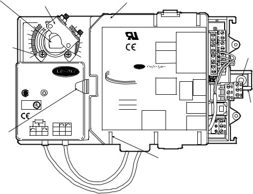
Figure 2 shows the zone controller physical details. Figures 3-5 show the 3 different types of zone controllers.
Field-Supplied Hardware — Each zone controller requires the following field-supplied components to complete its installation:
•air terminal unit
•space temperature sensor
•transformer — 24 vac, 40 va
•two no. 10 x 1/2-in. sheet metal screws (to secure SAT sensor to duct, if required)
•two no. 6-32 x 5/8-in. screws (to mount SPT sensor base to electrical box)
•contactors (if required for fan or electric heat)
•supply air temperature sensor (required for terminal with ducted heat)
•indoor air quality sensor (if required)
•relative humidity sensor (if required)
•one SPST (for each stage of electric heat, not required for Carrier fan terminals)
•valve and actuator for hot water heat (if required)
•delta pressure airflow pickup
NOTE: When selecting an airflow pickup, it is the designer's responsibility to select a sensor that provides the desired output at the design airflow.
•wire
•polyethylene tubing (for pressure pickup)
•bushings (required when mounting SAT sensor in a duct 6-in. or less in diameter)
•primary air temperature sensor (if required)
SPACE TEMPERATURE SENSOR — Each zone controller requires a field-supplied Carrier space temperature sensor. There are two sensors available for this application:
•33ZCT55SPT, Space Temperature Sensor with Override Button
•33ZCT56SPT, Space Temperature Sensor with Override Button and Set Point Adjustment
PRIMARY AIR TEMPERATURE SENSOR — A fieldsupplied, primary air temperature (PAT) sensor (part number 33ZCSENPAT) is used on a zone controller which is functioning as a Linkage Coordinator for a non CCN/Linkage compatible air source.
SUPPLY AIR TEMPERATURE (SAT) SENSOR — On stand-alone applications or applications with ducted heat, the zone controller must be connected to a field-supplied supply air temperature (SAT) sensor (part number 33ZCSENSAT) to monitor the temperature of the air delivered by the air terminal. The zone controller will maintain the air temperature below the maximum air temperature in ducted heating applications.
2
CCN
SYSTEM
CCN PRIMARY BUS (BUS 0) MONITORING
SOFTWARE
FULLY |
CC6400 OR CSAM |
|
EQUIPPED |
||
COMPATIBLE |
||
NON-CCN |
||
AIR HANDLER |
||
AIR HANDLER |
||
|
BRIDGE (RECOMMENDED)
COMFORTID
EQUIPPED
AIR TERMINAL
SECONDARY BUS (1 OF UP TO 128)
ADDRESSED
SEQUENTIALLY
DATA
COLLECTION
OPTION
LEGEND
CCN — Carrier Comfort Network
CSAM — Comfort System AirManager
Fig. 1 — Typical Carrier Linkage System
3
DAMPER |
ACTUATOR |
|
LOW PRESSURE |
||||||
SHAFT |
CLAMP |
|
TUBING ROUTING |
||||||
|
ASSEMBLY |
|
|
||||||
|
|
|
|
|
|
|
|
|
|
|
|
|
|
|
|
|
|
|
|
|
|
|
|
|
|
|
|
|
|
|
|
|
|
|
|
|
|
|
|
|
|
|
|
|
|
|
LOW |
|
|
|
|
|
15 |
|
+24V |
16 |
|
|
|
|
|
|
|
|
C |
|
US |
|
|
|
RH/IAQ |
SPT |
|
|
|
|
|
|
|
|
|
|
|
|
|
|
|
GND |
|
|
|||
MECHANICAL |
|
|
|
|
|
|
|
|
1 |
J6 |
|
FAN AC |
|
GND |
|
||
|
|
|
|
|
|
|
|
|
|
SECFLOW |
|
||||||
|
|
|
|
|
|
|
|
|
|
|
|
|
|||||
STOP |
|
|
|
|
|
|
|
|
1 2 |
|
FAN |
SAT |
|
|
|||
|
|
|
|
|
|
|
|
|
|
|
24VAC |
J4 |
+10V |
T56 |
|
GROMMET |
|
|
|
|
|
|
|
|
|
|
|
J7 |
|
DMPPOS |
|
||||
|
0 |
|
|
|
|
|
1 |
|
|
|
N/A |
GND |
|||||
|
|
|
|
|
|
|
|
|
|
HEAT3 |
|
GND |
|
||||
|
|
|
|
|
|
|
3 |
|
|
|
|
|
|
||||
|
|
|
|
|
|
|
|
|
|
|
PAT |
|
|
||||
|
|
|
|
|
|
|
|
|
|
|
|
|
TEST |
|
|
||
|
|
|
|
|
|
|
|
|
|
|
|
|
REMOTE |
||||
|
|
|
|
|
|
|
|
|
® |
|
|
|
|
GND |
|||
|
HF23BJ042 |
|
|
|
|
ZONE Controller |
|
|
|
|
|||||||
|
|
|
|
|
1 |
|
|
|
2 |
||||||||
|
Made in Switzerland |
|
|
|
® |
|
1 |
|
|||||||||
|
by Belimo Automation |
|
35 in-lb (4 Nm) |
|
|
1 |
|
SECDMP |
|
1 |
|
|
|
|
|||
|
|
|
|
|
|
3 |
J8 |
|
CCNJ2A |
G- |
3 |
|
G- |
||||
|
|
|
|
80...110s |
|
|
|
|
|
|
COM |
|
|
LEN |
|
+ |
|
|
|
|
|
|
|
|
|
|
|
CW |
|
|
|
|
|
||
|
LR 92800 |
|
|
|
|
|
3art Number: 33ZCFANTRM |
|
|
COW |
|
+ |
J2B |
|
|
||
|
|
|
|
|
|
|
|
|
|
|
|
|
|||||
|
|
|
|
|
|
|
S/N: |
|
|
|
|
|
|
|
|
|
|
|
|
|
|
|
|
|
|
|
|
|
|
|
|
|
|
|
|
|
NEMA 2 |
|
|
|
|
|
Bus#: |
|
|
|
|
|
|
|
|
|
|
|
LISTED |
|
|
|
|
|
Element#: |
|
|
|
|
|
3 |
|
|
|
|
|
94D5 |
|
|
|
|
|
|
|
|
|
|
|
J3 |
SRVC |
|
ANTI- |
|
|
TENP IND & |
|
|
|
|
|
Unit#: |
|
|
|
|
|
|
|
|||
|
REG. EQUIP. |
|
|
|
|
|
|
|
|
|
|
|
|
|
|
||
|
Class 2 Supply |
|
|
|
|
|
|
|
|
|
|
|
|
|
|
|
ROTATION |
|
|
|
|
24VAC/DC |
|
|
|
J6 |
|
|
|
|
|
|
|
TAB |
|
|
|
|
|
50/60 Hz |
|
HIGH |
|
CCW COM CW HEAT1 |
24VAC |
HEAT2 |
|
3 J1 |
24VAC |
G |
|||
|
|
5K |
|
3VA 2W |
|
|
|
|
|
|
|
1 |
|
|
+ |
||
|
|
|
|
|
|
|
|
|
|
|
|
|
|||||
|
|
|
|
|
|
|
|
|
|
|
|
|
|
|
- |
||
|
|
|
|
COM |
|
|
|
1 |
|
|
|
6 |
|
|
|
||
|
|
|
|
|
|
|
|
|
|
|
|
|
|
|
|||
ACTUATOR |
|
WIP |
|
1 |
2 |
3 |
|
|
|
|
|
|
|
|
|
|
|
yel |
|
|
|
|
|
|
|
|
|
|
|
|
|
||||
RELEASE |
blu |
ora |
blk |
red |
wht |
|
|
|
|
|
|
|
|
|
|
|
|
|
|
|
|
|
|
|
|
|
|
|
|
|
|
|
|
|
|
BUTTON |
|
|
|
|
|
|
|
|
|
|
|
|
|
|
|
|
|
HIGH PRESSURE TUBING ROUTING
NOTE: Actuator clamp accepts dampers shafts with the following characteristics: Round — 1/4-in. to 5/8-in.
(6 to 16 mm) Square — 1/4-in. to 7/16-in.
(6 to 11 mm)
Damper shaft must be a minimum of 1.5-in. (38 mm) long.
→Fig. 2 — Zone Controller Physical Details (33ZCFANTRM Shown)
R E L A T I V E H U M I D I T Y S E N S O R — The 33AMSENRHS000 relative humidity sensor is required for zone humidity control (dehumidification).
NOTE: The relative humidity sensor and CO2 sensor cannot be used on the same zone controller.
INDOOR AIR QUALITY (CO2) SENSOR — An indoor air quality sensor is required for optional demand control ventilation. The CGCDXSEN002A00 CO2 Sensor is an indoor, wall mounted sensor with an LED display. The CGCDXSEN003A00 CO2 Sensor is an indoor, wall mounted sensor without display.
NOTE: The relative humidity sensor and CO2 sensor cannot be used on the same zone controller.
Mount Zone Controller
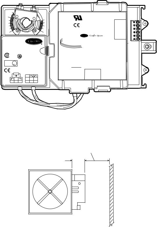
LOCATION — The zone controller must be mounted on the air terminal’s damper actuator shaft. For service access, there should be at least 12 in. of clearance between the front of the zone controller and adjacent surfaces. Refer to Fig. 6.
MOUNTING — Perform the following steps to mount the zone controller:
1.Visually inspect the damper and determine the direction in which the damper shaft moves to open the damper — clockwise (CW) or counterclockwise (CCW). Refer to Fig. 7.
If the damper rotates CCW to open, it does not require any configuration changes.
If the damper rotates CW to open, then the damper actuator logic must be reversed. This is done in the software when performing system start-up and damper calibration test. Do not attempt to change damper rotation by changing wiring. This will upset the damper position feedback potentiometer readings.
2.Rotate the damper shaft to the fully closed position. Note direction of rotation.
3.Press the release button on the actuator and rotate the clamp in the same direction that was required to close the damper in Step 2.
4.Press the release button on the actuator and rotate the actuator back one position graduation. Release the button and lock the actuator in this position.
5.Mount the zone controller to the terminal by sliding the damper shaft through the actuator clamp assembly. Secure the zone controller to the duct by installing the screw provided through the grommet in the antirotation tab. Be sure the floating grommet is in the center of the slot. Failure to center the grommet may cause the actuator to stick or bind.
6.Tighten the actuator clamp assembly to the damper shaft. Secure by tightening the two 10-mm nuts.
7.If the damper has less than 90 degrees of travel between the fully open and fully closed positions, then a mechanical stop must be set on the actuator. The mechanical stop prevents the damper from opening past the maximum damper position. To set the mechanical stop, perform the following procedure:
a.Press the actuator release button and rotate the damper to the fully open position.
b.Using a Phillips screwdriver, loosen the appropriate stop clamp screw.
c.Move the stop clamp screw so that it contacts the edge of the cam on the actuator. Secure the stop clamp screw in this position by tightening the screw.
8.Verify that the damper opens and closes. Press the actuator release button and rotate the damper. Verify that the damper does not rotate past the fully open position. Release the button and lock the damper in the fully open position.
801 |
4 |

—
|
|
|
|
LOW |
|
|
|
|
|
15 |
|
|
16 |
|
|
|
|
C |
|
US |
|
|
|
RH/IAQ |
+24V |
||
|
|
|
|
|
|
|
|
SPT |
|
||||
|
|
|
|
|
|
|
|
|
GND |
|
|||
|
|
|
|
|
|
1 |
J6 |
|
FAN AC |
|
GND |
||
|
|
|
|
|
|
|
|
SECFLOW |
|||||
|
|
|
|
|
|
1 2 |
|
FAN |
SAT |
|
|||
|
|
|
|
|
|
|
|
24VAC |
J4 |
+10V |
T56 |
|
|
|
|
|
|
|
|
|
J7 |
|
DMPPOS |
|
|||
0 |
|
|
1 |
|
|
|
|
N/A |
GND |
||||
|
|
|
|
|
|
|
HEAT3 |
|
GND |
||||
|
|
|
|
3 |
|
|
|
|
|
||||
|
|
|
|
|
|
|
|
PAT |
|
||||
|
|
|
|
|
|
|
|
|
|
TEST |
|
||
|
|
|
|
|
|
|
|
|
|
REMOTE |
|||
|
|
|
|
|
|
® |
|
|
|
|
GND |
||
HF23BJ042 |
|
|
|
ZONE Controller |
|
|
|
||||||
|
|
|
1 |
|
|
2 |
|||||||
Made in Switzerland |
|
|
® |
|
1 |
||||||||
by Belimo Automation |
35 in-lb (4 Nm) |
|
|
3 |
J8 |
DMPSEC |
|
CCNJ2A |
G- |
3 |
G- |
||
|
|
|
1 |
|
|
CW |
1 |
|
LEN |
|
|||
|
80...110s |
|
|
|
|
|
|
|
|
+ |
|||
|
|
|
|
|
|
|
|
|
COM |
|
+ |
|
|
LR 92800 |
|
|
|
|
|
|
|
|
|
|
|
||
|
|
|
Part Number: 33ZCFANTRM |
|
|
COW |
|
|
J2B |
|
|||
|
|
|
|
|
|
|
|
|
|||||
|
|
|
|
S/N: |
|
|
|
|
|
|
|
|
|
|
|
|
|
|
|
|
|
|
|
|
|
|
|
NEMA 2 |
|
|
|
Bus#: |
|
|
|
|
|
|
|
|
|
LISTED |
|
|
|
Element#: |
|
|
|
|
|
3 |
|
|
|
94D5 |
|
|
|
|
|
|
|
|
|
J3 |
SRVC |
|
|
TENP IND & |
|
|
|
Unit#: |
|
|
|
|
|
|
|
||
REG. EQUIP. |
|
|
|
|
|
|
|
|
|
|
|
|
|
Class 2 Supply |
|
|
|
|
|
|
|
|
|
|
|
|
|
|
24VAC/DC |
|
|
|
J6 |
|
|
|
|
|
|
|
|
|
50/60 Hz |
|
HIGH |
|
CCW COM CW HEAT1 |
24VAC |
HEAT2 |
|
3 J1 |
24VAC |
G |
||
5K |
3VA 2W |
|
|
|
|
|
|
|
1 |
|
|
+ |
|
|
|
|
|
|
|
|
|
|
|
||||
|
|
|
|
|
|
|
|
|
|
|
|
- |
|
|
COM |
|
|
|
1 |
|
|
|
6 |
|
|
|
|
|
|
|
|
|
|
|
|
|
|
|
|||
WIP |
1 |
2 |
3 |
|
|
|
|
|
|
|
|
|
|
yel blu ora |
blk red wht |
→Fig. 3 — VAV Fan Terminal Zone Controller
LOW |
US |
C |
0 |
|
|
|
1 |
|
|
|
|
|
|
|
|
® |
HF23BJ042 |
|
|
|
ZONE Controller |
||
Made in Switzerland |
|
|
® |
|||
by Belimo Automation |
35 in-lb (4 Nm) |
|
|
|
||
|
|
|
|
|||
|
80...110s |
|
|
|
|
|
LR 92800 |
|
|
|
Part Number: 33ZCVAVTRM |
|
|
|
|
|
|
|
||
|
|
|
|
S/N: |
|
|
NEMA 2 |
|
|
|
Bus#: |
|
|
LISTED |
|
|
|
Element#: |
|
|
94D5 |
|
|
|
|
|
|
TENP IND & |
|
|
|
Unit#: |
|
|
REG. EQUIP. |
|
|
|
|
|
|
Class 2 Supply |
|
|
|
|
|
|
|
24VAC/DC |
|
|
|
J6 |
|
|
50/60 Hz |
|
HIGH |
1 |
CCW COM CW HEAT1 24VAC HEAT2 |
|
5K |
3VA 2W |
|
||||
|
|
|
|
|||
|
|
|
|
|
|
|
|
COM |
|
|
|
|
|
WIP |
1 |
2 |
3 |
|
|
|
yel blu ora |
blk |
red |
wht |
|
|
|
6
15 |
|
|
16 |
|
RH/IAQ |
+24V |
|||
SPT |
|
|||
|
GND |
|
||
|
GND |
|||
SECFLOW |
||||
SAT |
|
|||
J4 |
+10V |
|
||
T56 |
|
|||
DMPPOS |
|
|||
GND |
||||
|
GND |
|||
|
PAT |
|
||
TEST |
|
|||
|
GND REMOTE |
|||
1 |
|
1 |
2 |
|
1 |
|
|
||
|
LEN |
|
||
CCNJ2A |
|
+ |
||
G- |
3 |
G- |
||
|
+ |
J2B |
|
|
|
|
|
||
3 |
|
|
|
|
|
J3 |
SRVC |
|
|
1 |
|
24VAC |
+ |
|
3 |
J1 |
G |
||
|
|
|
- |
|
→Fig. 4 — Single Duct Air Terminal Zone Controller
5 |
801 |
LOW |
® |
|
|
|
C |
|
US |
6 |
|
|
|
|
|
|
J1 |
0 |
|
|
1 |
|
|
|
|
|
|
|
|
® |
1 |
|
|
|
|
|
|
|
H F 2 3 B J 0 4 2 |
|
|
ZONE Controller |
|||
M a d e i n S w i t z e r l a n d |
|
|
|
|
|
|
b y B e l i m o A u t o m a t i o n |
35 in-lb (4 Nm) |
|
|
|
||
|
|
|
|
|||
|
80...110s |
|
|
|
|
|
L R 9 2 8 0 0 |
|
|
Part Number: 33ZCSECTRM |
|
||
|
|
|
|
|||
|
|
|
S/N: |
|
|
|
NEMA2 |
|
|
|
|
|
|
LISTED |
|
|
|
|
|
|
94D5 |
|
|
|
|
|
|
TEMP. IND. & UL |
|
|
|
|
|
|
REG. EQUIP. |
|
|
Unit#: |
|
|
|
Class 2 Supply |
24VAC/DC |
|
|
|
||
|
|
|
|
|
||
|
50/60Hz |
|
|
J2 |
|
|
5K |
3VA |
2W |
HIGH |
|
CCW COM CW N/A N/A N/A |
|
|
|
|
|
|||
|
COM |
|
|
|
|
|
WIP |
1 |
2 |
3 |
1 |
|
6 |
yel blu ora |
blk |
red |
wht |
|
|
|
GND |
D |
OUT |
TPUT |
|
FLOW |
+10V |
OV |
CW |
|
COM |
MMON |
|
|
CCW |
CW |
|
|
|
J1 |
Fig. 5 — Secondary Terminal Zone Controller
ALLOW 12” CLEARANCE FOR SERVICE
ACCESS TO CONTROL BOX
3” REF.
ZONE
CONTROLLER
END VIEW INLET
Fig. 6 — Service Clearance for Zone Controller Mounting
6
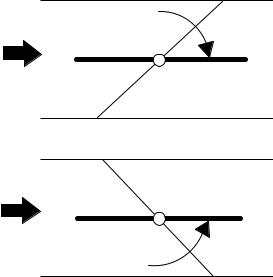
AIR
FLOW
CW TO OPEN, CCW TO CLOSE
AIR
FLOW
CCW TO OPEN, CW TO CLOSE
Fig. 7 — Damper Configuration
Connect the Power Transformer — An individual, field-supplied, 24 vac power transformer is recommended for each zone controller. If multiple zone controllers are powered from one power transformer (100 va maximum for UL [Underwriters’ Laboratories] Class 2 conformance), maintain polarity on the power input terminals. All transformer secondaries are required to be grounded. Use only stranded copper conductors for all wiring to the zone controller. Wiring connections must be made in accordance with NEC (National Electrical Code) and local codes. Ground the transformer at the transformer location. Provide an 18-gage, green, chassis ground wire at the terminal.
The power supply is 24 vac ± 10% at 40 va (50/60 Hz).
For 33ZCVAVTRM zone controllers, the power requirement sizing allows for accessory water valves and for electric heat contactor(s). Water valves are limited to 15 va on both two-position and modulating hot water. The electric heat contactor(s) are limited to 10 va (holding) each.
For 33ZCFANTRM zone controllers, the power requirement sizing allows for accessory water valves and for the fan contactor. Water valves are limited to 8 va on both two-position and modulating hot water. The fan contactor is limited to 11 va (holding).
NOTE: If a water valve or electric heat contactor exceeds these limits, or external contactors are required for electric heat, then it is recommended a 60 va transformer be used. The maximum rating for any output is 20 va.
NOTE: Do not run sensor or communication wiring in the same conduit with line-voltage wiring.
NOTE: An accessory conduit box (part no. 33ZCCONBOX) is available for conduit wiring connections to the zone controller.
Perform the following steps to connect the power transformer:
1.Install the field-supplied transformer in an electrical enclosure that conforms to NEC and local codes.
2.Connect 24 vac from the transformer as shown in the applicable wiring diagram (Fig. 8A-J).
Connect Airflow Pickups — The zone controller determines velocity pressure by obtaining the difference between high and low duct pressure from two airflow pickups. The pickups are connected to barb fittings on the zone controller with 1/4-in. polyethylene tubing. All piping for this purpose must conform to local codes.
Figure 9 indicates the positions of the two barb fittings.
Perform the following steps to install and connect the airflow pickups:
1.Select a location on the air handler’s supply air duct where the airflow pickups will be installed. The location should be one where there are at least three duct diameters of straight duct upstream of the pickups. If this requirement is not met, stable airflow measurements may not be possible.
2.Mount the field-supplied airflow pickup(s) in the duct, following the manufacturer's directions. Two individual pickups may be used, one for high pressure airflow and one for low pressure airflow. A dual pickup, which combines the two functions, may also be used. When using individual pickups, make sure that the one for high pressure airflow faces upstream, in the direction the air is coming from, and the one for low pressure airflow faces downstream, in the direction the air is going to.
3.Use field-supplied 1/4-in. tubing (rated for the application) to connect the high pressure airflow pickup to barb fitting P1 on the pressure transducer. At the zone controller, the P1 fitting is on the side with the filter installed. Be careful to avoid sharp bends in the tubing, because malfunctions may occur if the tubing is bent too sharply. Use at least 2 ft of tubing for reading stability.
4.Use field-supplied 1/4-in. tubing (rated for the application) to connect the low pressure airflow pickup to barb fitting P2 on the pressure transducer. Be careful to avoid sharp bends in the tubing, because malfunctions may occur if the tubing is bent too sharply. Use at least 2 feet of tubing for stability.
7
303 |
|
|
|
|
|
|
|
|
+24V |
|
|
|
|
|
|
|
|
|
|
RH/IAQ |
SPT |
SPT |
|
|
|
|
|
|
|
|
|
|
|
||
|
|
|
|
|
|
|
|
GND |
|
|
|
|
|
|
|
|
|
|
|
|
GND |
SAT |
|
|
|
|
|
|
|
|
|
SECFLOW |
SAT |
|
|
|
|
|
|
|
Low |
|
|
Y |
|
|
|
|
|
|
|
|
|
|
|
|
|
||
|
|
|
|
|
|
|
|
+10V |
|
|
|
|
|
|
|
|
|
|
|
|
T56 |
|
|
|
|
|
|
|
|
|
|
DMPPOS |
|
|
|
|
|
|
|
|
|
|
|
Bl |
GND |
|
|
|
|
|
|
|
|
|
|
|
|
|
|
|
|
|
|
|
|
|
|
GND |
|
|
|
|
|
|
|
|
|
|
|
Or |
PAT |
|
|
|
|
|
|
|
|
|
|
|
|
|
|
|
|
0 |
1 |
|
|
|
N/A |
|
|
|
|
|
|
|
|
|
|
REMOTE |
|
|
|||
|
|
|
|
|
|
|
|
|
|
|
|
|
|
|
|
|
|
|
|
GND |
|
|
|
HF23BJ042 |
|
|
|
|
|
|
|
|
|
||
Made in Switzerland |
|
|
|
|
|
|
|
|
|
|
|
By Belimo Automation |
|
35 in-lb(4Nm) |
|
|
|
|
|
|
|
||
|
|
|
|
|
|
|
|
|
|
|
|
|
|
|
|
80...110s |
|
|
|
|
|
|
|
|
|
|
|
|
|
|
|
(+) |
R |
|
|
|
|
|
|
|
|
|
|
(GND) |
W |
|
|
|
|
|
|
|
|
|
|
(-) |
B |
Not used |
|
|
|
|
|
|
|
|
|
|
|
|
|
|
|
|
24VAC/DC |
|
|
|
|
|
|
|
|
|
|
|
50/60Hz |
Hi |
|
|
|
|
CCN comunications |
||
8 |
|
|
3VA 2W |
|
|
|
|
|
|
||
|
|
|
|
|
|
|
|
|
|
|
|
|
|
|
|
|
|
|
|
|
|
CCN comunications |
|
|
|
|
com |
|
|
|
|
|
|
|
|
|
|
|
|
|
W |
B |
R |
HEAT1 24VAC HEAT2 |
|
24 VAC |
Line Voltage |
Yel |
Blu |
Ora |
Blk |
Red |
Wht |
|
|
|
|
TRAN |
|
|
|
|
|
|
|
|
|
|
|
TRANSFORMER |
|
|
|
|
|
|
|
|
|
|
|
GROUND |
|
|
|
|
|
|
|
|
|
|
|
TERMINAL |
|
|
|
|
|
|
|
|
|
|
|
GROUND |
|
|
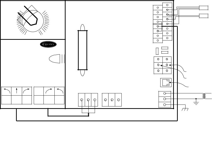
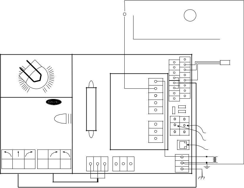
LEGEND |
|
|
|
|
|
|
|
|
|
|
CCN |
— Carrier Comfort Network |
SAT |
— Supply-Air Temperature Sensor |
SPT |
— Space Temperature Sensor |
TRAN |
— Transformer |
|
Field Wiring |
|
Factory Wiring |
→Fig. 8A — Zone Controller Wiring — Single Duct Air Terminal, Cooling Only
|
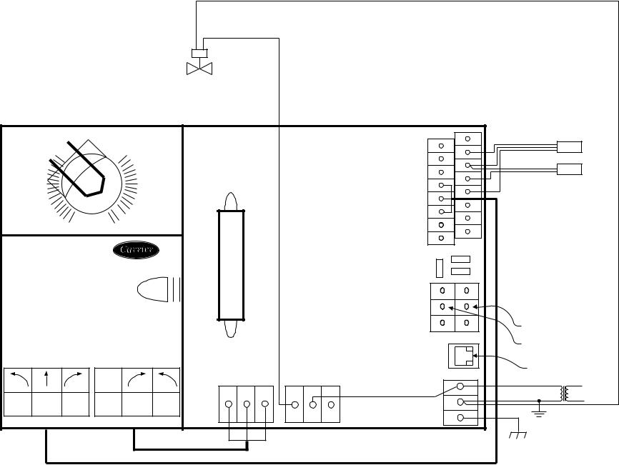
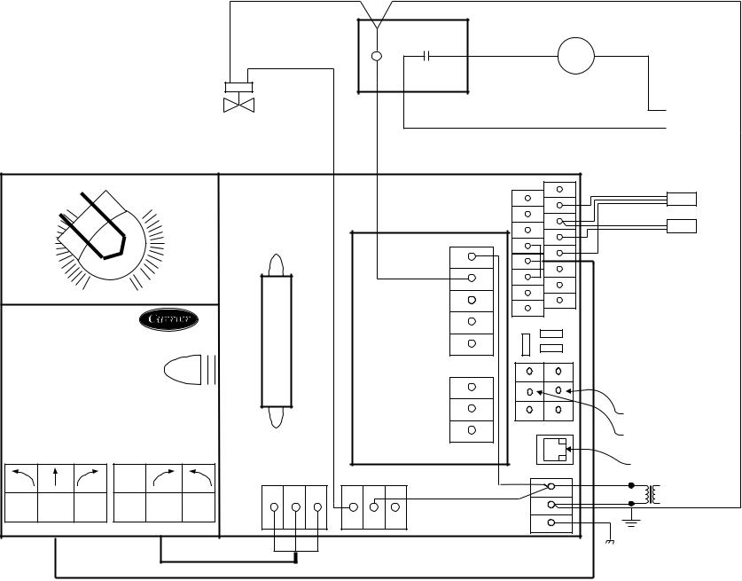
LEGEND |
|
CCN |
— Carrier Comfort Network |
|
HWV |
— Hot Water Valve |
|
SAT |
— Supply-Air Temperature Sensor |
|
SPT |
— Space Temperature Sensor |
|
TRAN |
— Transformer |
|
|
Field Wiring |
HWV |
|
Factory Wiring |
|
*Normally open or normally closed valve may be used.
|
|
|
|
|
|
|
|
|
|
+24V |
|
|
|
|
|
|
|
|
|
|
RH/IAQ |
|
SPT |
|
|
|
|
|
|
|
|
|
|
SPT |
|
|
|
|
|
|
|
|
|
|
GND |
|
|
|
|
|
|
|
|
|
|
|
|
GND |
SAT |
|
|
|
|
|
|
|
|
|
SECFLOW |
|
|
|
|
|
|
|
|
|
|
|
|
|
|
|
|
|
|
|
|
Low |
|
|
|
SAT |
|
|
|
|
|
|
|
|
|
+10V |
|
|
|
|
|
|
|
|
|
|
|
|
Y |
T56 |
|
|
|
|
|
|
|
|
|
|
DMPPOS |
|
|
|
|
|
|
|
|
|
|
|
Bl |
GND |
|
|
|
|
|
|
|
|
|
|
|
|
|
|
|
|
|
|
|
|
|
|
GND |
|
|
|
|
|
|
|
|
|
|
|
Or |
PAT |
|
|
|
|
|
|
|
|
|
|
|
|
|
|
|
|
0 |
1 |
|
|
|
N/A |
|
|
|
|
|
|
|
|
|
|
REMOTE |
|
|||
|
|
|
|
|
|
|
|
|
|
|
|
|
|
|
|
|
|
|
|
|
GND |
|
|
9 |
HF23BJ042 |
|
|
|
|
|
|
|
|
||
|
|
|
|
|
|
|
|
|
|||
|
Made in Switzerland |
|
|
|
|
|
|
|
|
|
|
|
By Belimo Automation |
|
35 in-lb(4Nm) |
|
|
|
|
|
|
||
|
|
|
|
|
|
|
|
|
|
|
|
|
|
|
|
|
80...110s |
|
|
|
|
|
|
|
|
|
|
|
|
|
|
|
(+) |
R |
|
|
|
|
|
|
|
|
|
|
(GND) |
W |
|
|
|
|
|
|
|
|
|
|
(-) |
B |
|
|
|
|
|
|
|
|
|
|
|
Not used |
|
|
|
|
|
24VAC/DC |
|
|
|
|
|
|
|
|
|
|
|
50/60Hz |
Hi |
|
|
|
CCN comunications |
||
|
|
|
|
3VA 2W |
|
|
|
|
|
||
|
|
|
|
|
|
|
|
|
|
||
|
|
|
|
|
|
|
|
|
|
CCN comunications |
|
|
|
|
|
com |
|
|
|
|
|
|
|
|
|
|
|
|
|
W |
B |
R |
HEAT1 24VAC HEAT2 |
24 VAC |
Line Voltage |
|
|
|
|
|
|
|
|||||
|
Yel |
Blu |
Ora |
Blk |
Red |
Wht |
|
|
|
TRAN |
|
|
|
|
|
|
|
|
|
|
|
||
|
|
|
|
|
|
|
|
|
|
TRANSFORMER |
|
|
|
|
|
|
|
|
|
|
|
GROUND |
|
|
|
|
|
|
|
|
|
|
|
TERMINAL |
|
|
|
|
|
|
|
|
|
|
|
GROUND |
|
303
→Fig. 8B — Zone Controller Wiring — Single Duct Air Terminal, Two-Position Hot Water Heat
303
10
|
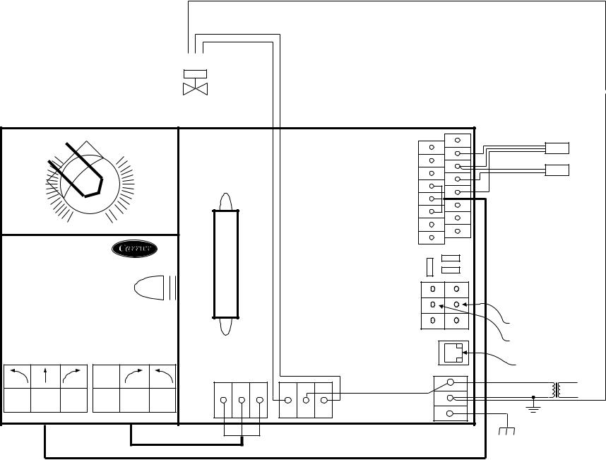
LEGEND |
|
|
|
CCN |
— Carrier Comfort Network |
|
|
|
HWV |
— Hot Water Valve |
|
|
|
SAT |
— Supply-Air Temperature Sensor |
|
|
|
SPT |
— Space Temperature Sensor |
|
|
|
TRAN |
— Transformer |
|
|
|
|
Field Wiring |
COM |
CL |
OP |
|
Factory Wiring |
|
|
|
HWV
*Required for some spring return modulating valves.
|
|
|
|
|
|
|
|
|
+24V |
|
|
|
|
|
|
|
|
|
|
RH/IAQ |
SPT |
SPT |
|
|
|
|
|
|
|
|
|
|
|||
|
|
|
|
|
|
|
|
GND |
|
|
|
|
|
|
|
|
|
|
|
|
GND |
|
|
|
|
|
|
|
Low |
|
|
SECFLOW |
SAT |
SAT |
|
|
|
|
|
|
|
|
|
|
|
||
|
|
|
|
|
|
|
+10V |
|
|
|
|
|
|
|
|
|
|
|
|
|
|
|
|
|
|
|
|
|
|
|
|
Y |
T56 |
|
|
|
|
|
|
|
|
|
|
DMPPOS |
|
|
|
|
|
|
|
|
|
|
|
Bl |
GND |
|
|
|
|
|
|
|
|
|
|
|
|
|
|
|
|
|
|
|
|
|
|
GND |
|
|
|
|
|
|
|
|
|
|
|
Or |
PAT |
|
|
|
|
|
|
|
|
|
|
|
|
|
|
|
|
0 |
1 |
|
|
|
|
N/A |
|
|
|
|
|
|
|
|
|
|
REMOTE |
|
|
||
|
|
|
|
|
|
|
|
|
|
|
|
|
|
|
|
|
|
|
|
GND |
|
|
|
HF23BJ042 |
|
|
|
|
|
|
|
|
|
||
Made in Switzerland |
|
|
|
|
|
|
|
|
|
|
|
By Belimo Automation |
35 in-lb(4Nm) |
|
|
|
|
|
|
|
|||
|
|
|
|
|
|
|
|
|
|
||
|
|
|
80...110s |
|
|
|
|
|
|
|
|
|
|
|
|
|
|
|
|
(+) |
R |
|
|
|
|
|
|
|
|
|
|
(GND) |
W |
|
|
|
|
|
|
|
|
|
|
(-) |
B |
Not used |
|
|
|
|
|
|
|
|
|
|
|
|
|
|
|
|
24VAC/DC |
|
|
|
|
|
|
|
|
|
|
|
50/60Hz |
Hi |
|
|
|
|
CCN comunications |
||
|
|
|
3VA |
2W |
|
|
|
|
|
|
|
|
|
|
|
|
|
|
|
|
|
||
|
|
|
|
|
|
|
|
|
|
CCN comunications |
|
|
|
|
com |
|
|
|
|
|
|
|
|
|
|
|
|
|
W |
B |
R |
HEAT1 24VAC HEAT2 |
|
24 VAC |
Line Voltage |
|
|
|
|
|
|
|
|
|
|
||
Yel |
Blu |
Ora |
Blk |
Red |
Wht |
|
|
|
|
TRAN |
|
|
|
|
|
|
|
|
|
|
|
||
|
|
|
|
|
|
|
|
|
|
TRANSFORMER |
|
|
|
|
|
|
|
|
|
|
|
GROUND |
|
|
|
|
|
|
|
|
|
|
|
TERMINAL |
|
|
|
|
|
|
|
|
|
|
|
GROUND |
|
→Fig. 8C — Zone Controller Wiring — Single Duct Air Terminal, Modulating Hot Water Heat
|
LEGEND |
|
|
|
|
|
|
|
|
|
|
|
CCN |
— Carrier Comfort Network |
|
|
|
|
|
|
|
|
|
|
|
H |
— Heater Relay |
|
|
|
|
|
|
|
|
|
|
|
HWV |
— Hot Water Valve |
|
|
|
|
|
|
|
|
|
|
|
SAT |
— Supply-Air Temperature Sensor |
|
|
|
|
|
|
|
|
|
|
|
|
|
|
|
|
|
|
|
|
|
|
||
SPT |
— Space Temperature Sensor |
|
|
|
H2 |
|
|
|
|
H1 |
||
|
|
|
|
|
||||||||
TRAN |
— Transformer |
|
|
|
|
|
|
|
|
|
|
|
|
Field Wiring |
|
|
|
|
|
|
|
|
|
|
|
|
|
|
|
|
|
|
|
|
|
|
|
|
|
Factory Wiring |
|
|
|
|
|
|
|
|
|
|
|
|
|
|
|
|
|
|
|
|
|
+24V |
|
|
|
|
|
|
|
|
|
|
|
RH/IAQ |
|
|
SPT |
|
|
|
|
|
|
|
|
|
|
SPT |
|
|
|
|
|
|
|
|
|
|
|
GND |
|
|
|
|
|
|
|
|
|
|
|
|
|
GND |
|
SAT |
|
|
|
|
|
|
Low |
|
|
SECFLOW |
SAT |
|
|
|
|
|
|
|
|
|
|
|
|
|
||
|
|
|
|
|
|
|
|
Y+10V |
|
|
|
|
|
|
|
|
|
|
|
|
|
T56 |
|
|
|
|
|
|
|
|
|
|
|
|
|
|
|
|
|
|
|
|
|
|
|
|
|
DMPPOS |
|
|
|
|
|
|
|
|
|
|
|
|
Bl |
GND |
|
|
|
|
|
|
|
|
|
|
|
|
|
|
|
|
|
|
|
|
|
|
|
|
GND |
|
|
|
|
|
|
|
|
|
|
|
|
Or |
PAT |
|
|
|
|
|
|
|
|
|
|
|
|
|
|
|
|
|
0 |
|
1 |
|
|
|
|
N/A |
|
|
|
|
|
|
|
|
|
|
|
REMOTE |
|
|
||
|
|
|
|
|
|
|
|
|
|
|
|
|
|
|
|
|
|
|
|
|
|
GND |
|
|
|
11 |
HF23BJ042 |
|
|
|
|
|
|
|
|
|
|
|
|
Made in |
|
35 in-lb(4Nm) |
|
|
|
|
|
|
|
||
|
|
|
|
|
|
|
|
|
|
|||
|
|
Switzerland |
|
|
|
|
|
|
|
|
||
|
|
|
80...110s |
|
|
|
|
|
|
|
||
|
|
By Belimo |
|
|
|
|
|
|
|
|
||
|
|
Automation |
|
|
|
|
|
|
|
|
|
|
|
|
|
|
|
|
|
|
|
(+) |
R |
|
|
|
|
|
|
|
|
|
|
|
(GND) |
W |
|
|
|
|
|
|
|
|
|
|
|
(–) |
B |
Not Used |
|
|
|
|
|
|
|
|
|
|
|
|
|
|
|
|
|
|
24VAC/DC |
|
|
|
|
|
|
|
|
|
|
|
|
50/60Hz |
Hi |
|
|
|
|
CCN |
|
|
|
|
|
|
3VA |
2W |
|
|
|
|
comunications |
||
|
|
|
|
|
|
|
|
|
|
|
CCN |
|
|
|
|
|
com |
|
|
|
|
|
|
comunications |
|
|
|
|
|
|
|
|
|
|
|
|
|
|
|
|
|
|
|
|
W |
B |
R |
HEAT1 24VAC HEAT2 |
|
24 VAC |
Line |
|
|
|
|
|
|
|
Voltage |
|||||
|
Yel |
Blu |
Ora |
Blk |
Red |
Wht |
|
|
|
|
|
|
|
|
|
|
|
TRAN |
|
||||||
|
|
|
|
|
|
|
|
|
|
|
|
|
|
|
|
|
|
|
|
|
|
|
|
TRANSFORMER |
|
|
|
|
|
|
|
|
|
|
|
|
GROUND |
|
|
|
|
|
|
|
|
|
|
|
|
TERMINAL |
|
|
|
|
|
|
|
|
|
|
|
|
GROUND |
|
→ Fig. 8D — Zone Controller Wiring — Single Duct Air Terminal, Staged Electric Heat (2 Stages)
801
303
12
|
|
|
|
|
|
|
|
|
|
|
|
|
|
|
LEGEND |
|
|
|
|
|
|
|
|
|
|
|
|
|
|
CCN |
— Carrier Comfort Network |
|
|
|
|
|
|
|
|
|
|
|
|
|
|
H |
— Heater Relay |
|
|
|
|
|
|
|
|
|
|
|
|
|
|
SAT |
— Supply-Air Temperature Sensor |
|
|
|
|
|
|
|
|
|
|
|
|
|
|
||
|
|
|
|
|
|
|
|
|
|
|
|
|
|
SPT |
— Space Temperature Sensor |
|
|
|
|
|
|
|
|
|
|
|
|
|
|
||
|
|
|
H3 |
|
|
|
|
H2 |
|
|
|
|
H1 |
TRAN |
— Transformer |
|
|
|
|
|
|
|
|||||||||
|
|
|
|
|
|
|
|
|
|
|
|
|
|
|
Field Wiring |
|
|
|
|
|
|
|
|
|
|
|
|
|
|
|
Factory Wiring |
|
|
|
|
|
|
|
|
|
|
|
|
|
|
|
|
|
|
|
|
|
|
|
|
|
|
|
|
|
|
NOTE: The VAV fan terminal zone controller is used on single duct air |
|
|
|
|
|
|
|
|
|
|
|
|
|
|
|
||
|
|
|
|
|
|
|
|
|
|
|
|
|
|
terminals with 3 stages of electric heat. |
|
|
|
|
|
|
|
|
|
|
|
|
+24V |
|
|
|
|
|
|
|
|
|
|
|
|
RH/IAQ |
|
SPT |
|
|
|
|
|
|
|
|
|
|
|
|
SPT |
|
|
|
|
|
|
|
|
|
|
|
|
GND |
GND |
|
|
|
|
|
|
|
|
|
|
|
|
|
|
|
|
|
|
|
|
|
|
|
|
|
|
SECFLOW |
|
SAT |
|
|
|
|
|
|
|
|
|
|
|
|
SAT |
|
|
|
|
|
|
|
Low |
|
|
|
|
|
|
|
|
|
|
|
|
|
|
|
|
|
+10V |
|
|
|
|
|
|
|
|
|
|
|
|
|
FAN AC |
Y |
T56 |
|
|
|
|
|
|
|
|
|
|
|
|
|
|
||
|
|
|
|
|
|
|
|
|
DMPPOS |
|
|
|
|
|
|
|
|
|
|
|
|
|
|
|
|
|
|
|
|
|
|
|
|
|
|
|
|
Bl |
GND |
|
|
|
|
|
|
|
|
|
|
|
|
|
|
|
|
|
|
|
|
|
|
|
|
|
FAN |
GND |
|
|
|
|
|
|
|
|
|
|
|
|
|
Or |
PAT |
|
|
|
|
|
|
|
|
|
|
|
|
|
|
|
|
|
|
0 |
1 |
|
|
|
|
24 VAC |
N/A |
|
|
|
|
|
|
|
|
|
|
|
REMOTE |
|
|
||||
|
|
|
|
|
|
|
|
|
|
|
|
|
|
|
|
|
|
|
|
|
|
|
|
GND |
|
|
|
HF23BJ042 |
|
|
|
|
|
|
Not Used |
|
|
|
|
||
|
|
|
|
|
|
|
|
|
|
|
|||
Made in Switzerland |
|
|
|
|
|
|
|
Heat3 |
|
|
|
|
|
By Belimo Automation |
|
35 in-lb(4Nm) |
|
|
|
|
|
|
|
|
|||
|
|
|
|
80...110s |
|
|
|
|
|
|
|
|
|
|
|
|
|
|
|
|
|
|
|
R |
R |
|
|
|
|
|
|
|
|
|
|
|
CW |
W |
W |
|
|
|
|
|
|
|
|
|
|
|
|
|
|
||
|
|
|
|
|
|
|
|
Second |
COM |
B |
B |
|
|
|
|
|
|
|
|
|
|
|
Not used |
|
|||
|
|
|
|
|
|
|
|
Damper |
|
|
|
|
|
|
|
|
24VAC/DC |
|
|
|
|
CCW |
|
|
|
|
|
|
|
|
50/60Hz |
Hi |
|
|
|
|
|
|
CCN comunications |
||
|
|
|
3VA 2W |
|
|
|
|
|
|
|
|
||
|
|
|
|
|
|
|
|
|
|
|
|
CCN comunications |
|
|
|
|
com |
|
|
|
|
|
|
|
|
|
|
|
|
|
|
|
W |
B |
R |
HEAT1 24VAC HEAT2 |
|
|
|
24 VAC |
Line Voltage |
|
|
|
|
|
|
|
|
|
|
|
|
||
Yel |
Blu |
Ora |
Blk |
Red |
Wht |
|
|
|
|
|
|
TRAN |
|
|
|
|
|
|
|
|
|
|
|
|
|
|
|
|
|
|
|
|
|
|
|
|
|
|
|
TRANSFORMER |
|
|
|
|
|
|
|
|
|
|
|
|
|
GROUND |
|
|
|
|
|
|
|
|
|
|
|
|
|
TERMINAL |
|
|
|
|
|
|
|
|
|
|
|
|
|
GROUND |
|
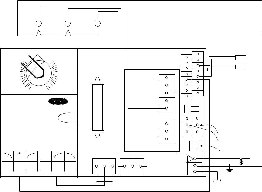
→Fig. 8E — Zone Controller Wiring — Single Duct Air Terminals, Staged Electric Heat (3-Stage)
LEGEND
CCN — |
Carrier Comfort Network |
|
Fan |
|
|
|
|
||
SPT — |
Space Temperature Sensor |
|
|
|
|||||
|
Contactor |
|
|
|
|
||||
TRAN — Transformer |
|
|
|
||||||
|
|
|
|
|
M |
|
|
||
|
Field Wiring |
|
|
|
|
|
|
|
|
|
|
|
|
|
|
||||
|
Factory Wiring |
|
|
|
|
Fan Motor |
|
||
|
|
|
|
|
|
|
|||
|
|
|
|
|
|
|
|
|
|
|
|
|
|
|
|
|
|
|
|
Line
Voltage
|
|
|
|
|
|
|
|
|
|
|
|
+24V |
|
|
|
|
|
|
|
|
|
|
|
|
|
RH/IAQ |
|
|
SPT |
|
|
|
|
|
|
|
|
|
|
|
|
SPT |
|
|
|
|
|
|
|
|
|
|
|
|
|
GND |
|
|
|
|
|
|
|
|
|
|
|
|
|
|
|
GND |
|
|
|
|
|
|
|
|
Low |
|
|
|
|
SECFLOW |
|
|
|
|
|
|
|
|
|
|
|
|
|
|
SAT |
|
|
|
|
|
|
|
|
|
|
|
|
|
Y+10V |
|
|
|
|
|
|
|
|
|
|
|
|
|
|
|
T56 |
|
|
|
|
|
|
|
|
|
|
|
|
|
FAN |
|
|
|
|
|
|
|
|
|
|
|
|
|
|
DMPPOS |
|
|
|
|
|
|
|
|
|
|
|
|
|
|
AC |
|
|
|
|
|
|
|
|
|
|
|
|
|
|
Bl |
GND |
|
|
|
|
|
|
|
|
|
|
|
|
|
|
|
|
||
|
|
|
|
|
|
|
|
|
|
|
|
|
|
|
|
|
|
|
|
|
|
|
|
|
FAN |
GND |
|
|
|
|
|
|
|
|
|
|
|
|
|
|
Or |
PAT |
|
|
|
|
|
|
|
|
|
|
|
|
|
|
|
|
|
|
|
0 |
|
1 |
|
|
|
|
|
24 VAC |
N/A |
|
|
|
|
|
|
|
|
|
|
|
|
REMOTE |
|
|
|||
|
|
|
|
|
|
|
|
|
|
|
|
|
|
|
13 |
|
|
|
|
|
|
|
|
|
|
GND |
|
|
|
HF23BJ042 |
|
|
|
|
|
|
Not |
|
|
|
|
|||
|
|
|
|
|
|
|
Used |
|
|
|
|
|||
|
Made in Switzerland |
|
35 in-lb(4Nm) |
|
|
|
|
Heat3 |
|
|
|
|
||
|
By Belimo Automation |
|
|
|
|
|
|
|
|
|
||||
|
|
|
|
|
|
|
|
|
|
|
||||
|
|
|
|
80...110s |
|
|
|
|
|
|
|
|
|
|
|
|
|
|
|
|
|
|
|
|
|
(+) |
R |
|
|
|
|
|
|
|
|
|
|
|
|
CW |
|
W |
|
|
|
|
|
|
|
|
|
|
|
|
|
|
|
|
|
|
|
|
|
|
|
|
|
|
|
COM |
(GND) |
|
|
|
|
|
|
|
|
|
|
|
|
Second |
|
B |
|
|
|
|
|
|
|
|
|
|
|
|
|
(–) |
Not Used |
|
||
|
|
|
|
|
|
|
|
|
Damper |
|
|
|
||
|
|
|
|
24VAC/DC |
|
|
|
|
CCW |
|
|
CCN |
|
|
|
|
|
|
50/60Hz |
Hi |
|
|
|
|
|
|
|
||
|
|
|
|
3VA |
2W |
|
|
|
|
|
|
comunications |
||
|
|
|
|
|
|
|
|
|
|
|
|
|
CCN |
|
|
|
|
|
com |
|
|
|
|
|
|
|
|
comunications |
|
|
|
|
|
|
|
|
|
|
|
|
|
|
|
|
|
|
|
|
|
|
W |
B |
R |
HEAT1 24VAC HEAT2 |
|
|
|
24 VAC |
Line |
|
Yel |
Blu |
Ora |
Blk |
Red |
Wht |
|
|
|
|
|
|
|
Voltage |
|
|
|
|
|
|
|
TRAN |
|
||||||
|
|
|
|
|
|
|
|
|
|
|
|
|
|
|
|
|
|
|
|
|
|
|
|
|
|
|
|
TRANSFORMER |
|
|
|
|
|
|
|
|
|
|
|
|
|
|
GROUND |
|
TERMINAL
GROUND
→Fig. 8F — Zone Controller Wiring — Fan Powered Terminals, Cooling Only
801
801
14
|
LEGEND |
|
CCN |
— Carrier Comfort Network |
|
HWV |
— Hot Water Valve |
Fan Contactor |
SAT |
— Supply-Air Temperature Sensor |
|
SPT |
— Space Temperature Sensor |
M |
TRAN |
— Transformer |
|
|
Field Wiring |
|
|
Factory Wiring |
Fan Motor |
|
|
|
|
|
|
|
HWV |
|
|
|
|
|
|
|
|
|
|
|
|
|
|
|
|
|
|
|
|
|
Line |
|
|
|
|
|
|
|
|
|
|
|
|
|
Voltage |
|
|
|
|
|
|
|
|
|
|
|
+24V |
|
|
|
|
|
|
|
|
|
|
|
|
RH/IAQ |
|
|
SPT |
|
|
|
|
|
|
|
|
|
|
|
SPT |
|
|
|
|
|
|
|
|
|
|
|
|
GND |
|
|
|
|
|
|
|
|
|
|
|
|
|
|
GND |
|
|
|
|
|
|
|
|
|
|
|
|
SECFLOW |
SAT |
|
SAT |
|
|
|
|
|
|
|
|
|
|
|
|
|
|
|
|
|
|
|
Low |
|
|
|
|
+10V |
|
|
|
|
|
|
|
|
|
|
|
FAN AC |
Y |
T56 |
|
|
|
|
|
|
|
|
|
|
|
|
|
DMPPOS |
|
|
|
|
|
|
|
|
|
|
|
|
|
Bl |
GND |
|
|
|
|
|
|
|
|
|
|
|
FAN |
GND |
|
|
|
|
|
|
|
|
|
|
|
|
|
Or |
PAT |
|
|
|
0 |
|
1 |
|
|
|
|
|
24 VAC |
N/A |
|
|
|
|
|
|
|
|
|
|
|
REMOTE |
|
|
|||
|
|
|
|
|
|
|
|
|
|
|
|
|
|
|
|
|
|
|
|
|
|
|
|
GND |
|
|
|
HF23BJ042 |
|
|
|
|
|
|
|
Not Used |
|
|
|
|
|
|
|
|
|
|
|
|
|
|
|
|
|
||
Made in Switzerland |
|
35 in-lb(4Nm) |
|
|
|
|
Heat3 |
|
|
|
|
||
By Belimo Automation |
|
|
|
|
|
|
|
|
|
|
|||
|
80...110s |
|
|
|
|
|
|
|
|
|
|||
|
|
|
|
|
|
|
|
|
|
|
|
||
|
|
|
|
|
|
|
|
|
|
(+) |
R |
|
|
|
|
|
|
|
|
|
|
|
CW |
(GND) |
W |
|
|
|
|
|
|
|
|
|
|
|
|
|
|
||
|
|
|
|
|
|
|
|
Second |
COM |
(-) |
B |
|
|
|
|
|
|
|
|
|
|
|
Not Used |
|
|||
|
|
|
|
|
|
|
|
Damper |
|
|
|
|
|
|
|
|
24VAC/DC |
|
|
|
|
CCW |
|
|
CCN |
|
|
|
|
|
50/60Hz |
Hi |
|
|
|
|
|
|
|
||
|
|
|
|
|
|
|
|
|
comunications |
||||
|
|
|
3VA |
2W |
|
|
|
|
|
|
|||
|
|
|
|
|
|
|
|
|
|
|
|
||
|
|
|
|
|
|
|
|
|
|
|
|
CCN |
|
|
|
|
com |
|
|
|
|
|
|
|
|
comunications |
|
|
|
|
|
|
|
|
|
|
|
|
|
|
|
|
|
|
|
|
W |
B |
R |
HEAT1 24VAC HEAT2 |
|
|
|
24 VAC |
Line |
|
|
|
|
|
|
|
|
Voltage |
|||||
Yel |
Blu |
Ora |
Blk |
Red |
Wht |
|
|
|
|
|
|
|
|
|
|
|
|
|
|
TRAN |
|
||||||
|
|
|
|
|
|
|
|
|
|
|
|
|
|
|
|
|
|
|
|
|
|
|
|
|
|
TRANSFORMER |
|
|
|
|
|
|
|
|
|
|
|
|
|
GROUND |
|
|
|
|
|
|
|
|
|
|
|
|
|
TERMINAL |
|
|
|
|
|
|
|
|
|
|
|
|
|
GROUND |
|
→Fig. 8G — Zone Controller Wiring — Fan Powered Terminals, Two-Position Hot Water Heat
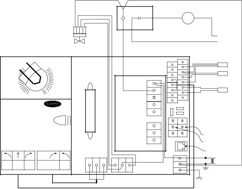
LEGEND
CCN — Carrier Comfort Network
HWV — Hot Water Valve
PAT — Primary Air Temperature Sensor
SAT — Supply-Air Temperature Sensor
SPT — Space Temperature Sensor
TRAN — Transformer
Field Wiring
Factory Wiring
Fan Contactor
M
Fan Motor
COM |
CL |
OP |
24V* |
HWV
Line
Voltage
*Required only on Linkage master if on a non-compatible air source.
|
|
|
|
|
|
|
|
|
|
|
+24V |
|
|
|
|
|
|
|
|
|
|
|
|
RH/IAQ |
|
|
SPT |
|
|
|
|
|
|
|
|
|
|
|
SPT |
|
|
|
|
|
|
|
|
|
|
|
|
GND |
|
|
|
|
|
|
|
|
|
|
|
|
|
|
GND |
|
SAT |
|
|
|
|
|
Low |
|
|
|
|
SECFLOW |
SAT |
|
|
|
|
|
|
|
|
|
|
|
|
|
|
||
|
|
|
|
|
|
|
|
|
Y+10V |
|
|
|
|
|
|
|
|
|
|
|
|
|
|
T56 |
|
|
|
|
|
|
|
|
|
|
|
|
FAN AC |
|
|
|
|
|
|
|
|
|
|
|
|
|
DMPPOS |
|
|
|
|
|
|
|
|
|
|
|
|
|
|
|
|
|
|
|
|
|
|
|
|
|
|
|
|
Bl |
GND |
|
|
|
|
|
|
|
|
|
|
|
|
|
|
|
|
|
|
|
|
|
|
|
|
|
FAN |
GND |
|
|
PAT* |
|
|
|
|
|
|
|
|
|
|
Or |
PAT |
|
|
|
|
|
|
|
|
|
|
|
|
|
|
|
|
|
0 |
|
1 |
|
|
|
|
|
24 VAC |
N/A |
|
|
|
|
|
|
|
|
|
|
|
REMOTE |
|
|
|||
15 |
|
|
|
|
|
|
|
|
|
|
|
||
|
|
|
|
|
|
|
|
|
GND |
|
|
|
|
|
|
|
|
|
|
|
|
|
|
|
|
|
|
HF23BJ042 |
|
|
|
|
|
|
|
Not |
|
|
|
|
|
|
|
|
|
|
|
|
Used |
|
|
|
|
||
Made in Switzerland |
|
35 in-lb(4Nm) |
|
|
|
|
Heat3 |
|
|
|
|
||
By Belimo Automation |
|
|
|
|
|
|
|
|
|
|
|||
|
80...110s |
|
|
|
|
|
|
|
|
|
|||
|
|
|
|
|
|
|
|
|
|
|
|
||
|
|
|
|
|
|
|
|
|
|
(+) |
R |
|
|
|
|
|
|
|
|
|
|
|
CW |
(GND) |
W |
|
|
|
|
|
|
|
|
|
|
|
|
|
|
||
|
|
|
|
|
|
|
|
Second |
COM |
(-) |
B |
|
|
|
|
|
|
|
|
|
|
|
Not Used |
|
|||
|
|
|
|
|
|
|
|
Damper |
|
|
|
|
|
|
|
|
24VAC/DC |
|
|
|
|
CCW |
|
|
CCN |
|
|
|
|
|
50/60Hz |
Hi |
|
|
|
|
|
|
|
||
|
|
|
|
|
|
|
|
|
comunications |
||||
|
|
|
3VA |
2W |
|
|
|
|
|
|
|||
|
|
|
|
|
|
|
|
|
|
|
|
||
|
|
|
|
|
|
|
|
|
|
|
|
CCN |
|
|
|
|
com |
|
|
|
|
|
|
|
|
comunications |
|
|
|
|
|
|
|
|
|
|
|
|
|
|
|
|
|
|
|
|
W |
B |
R |
HEAT1 24VAC HEAT2 |
|
|
|
24 VAC |
Line |
|
|
|
|
|
|
|
|
Voltage |
|||||
Yel |
Blu |
Ora |
Blk |
Red |
Wht |
|
|
|
|
|
|
|
|
|
|
|
|
|
|
TRAN |
|
||||||
|
|
|
|
|
|
|
|
|
|
|
|
|
|
|
|
|
|
|
|
|
|
|
|
|
|
TRANSFORMER |
|
|
|
|
|
|
|
|
|
|
|
|
|
GROUND |
|
|
|
|
|
|
|
|
|
|
|
|
|
TERMINAL |
|
|
|
|
|
|
|
|
|
|
|
|
|
GROUND |
|
801
→Fig. 8H — Zone Controller Wiring — Fan Powered Terminals, Modulating Hot Water Heat
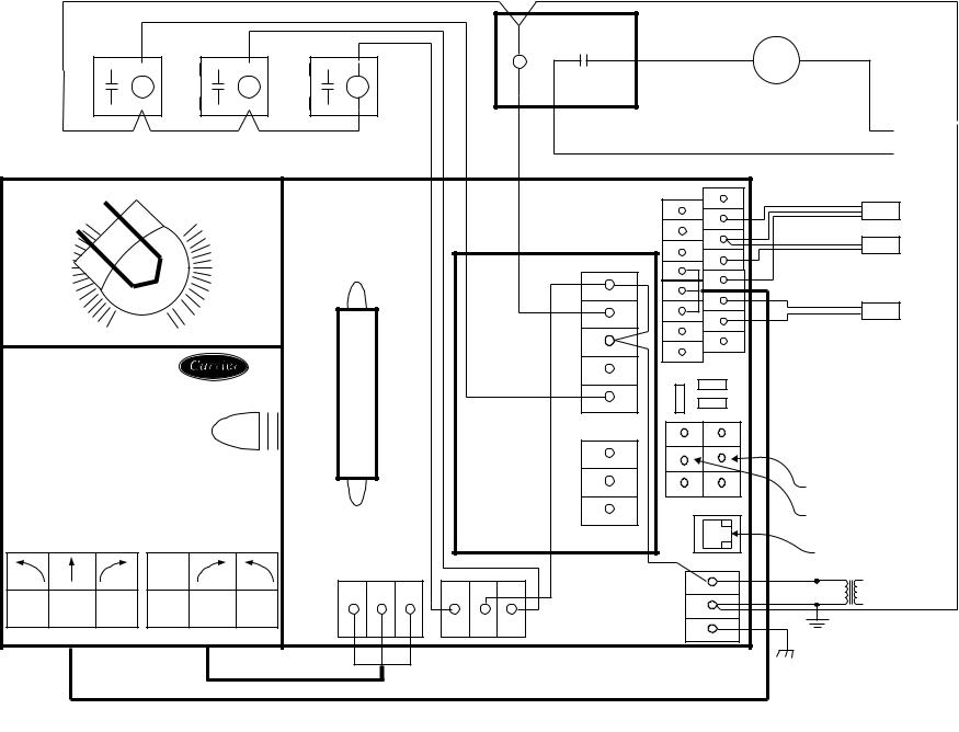
801
Fan Contactor
M
H3 |
H2 |
H1 |
Fan Motor
Line
Voltage
|
|
|
|
|
|
|
|
|
|
|
|
+24V |
|
|
|
|
|
|
|
|
|
|
|
|
RH/IAQ |
SPT |
SPT |
|
|
|
|
|
|
|
|
|
|
|
|
||
|
|
|
|
|
|
|
|
|
|
|
GND |
GND |
|
|
|
|
|
|
|
|
|
|
|
|
|
SAT |
|
|
|
|
|
|
|
Low |
|
|
|
|
SECFLOW |
SAT |
|
|
|
|
|
|
|
|
|
|
|
|
|
||
|
|
|
|
|
|
|
|
|
|
Y+10V |
|
|
|
|
|
|
|
|
|
|
|
|
|
FAN AC |
T56 |
|
|
|
|
|
|
|
|
|
|
|
|
|
|
||
|
|
|
|
|
|
|
|
|
|
DMPPOS |
|
|
|
|
|
|
|
|
|
|
|
|
|
|
|
|
|
|
|
|
|
|
|
|
|
|
|
|
Bl |
GND |
|
|
|
|
|
|
|
|
|
|
|
FAN |
GND |
|
PAT* |
|
|
|
|
|
|
|
|
|
|
|
Or |
PAT |
|
|
|
0 |
|
1 |
|
|
|
|
|
24 VAC |
N/A |
|
|
|
|
|
|
|
|
|
|
|
REMOTE |
|
|||
|
|
|
|
|
|
|
|
|
|
|
|
|
|
|
|
|
|
|
|
|
|
|
|
|
GND |
|
|
|
HF23BJ042 |
|
|
|
|
|
|
|
Not Used |
|
|
|
|
16 |
|
|
|
|
|
|
|
|
|
|
|
||
Made in Switzerland |
|
35 in-lb(4Nm) |
|
|
|
|
Heat3 |
|
|
|
|||
|
|
|
|
|
|
|
|
|
|||||
|
By Belimo Automation |
|
|
|
|
|
|
|
|
|
|||
|
|
|
|
80...110s |
|
|
|
|
|
|
|
|
|
|
|
|
|
|
|
|
|
|
|
|
(+) |
R |
|
|
|
|
|
|
|
|
|
|
|
CW |
(GND) |
W |
|
|
|
|
|
|
|
|
|
|
|
|
|
||
|
|
|
|
|
|
|
|
|
Second |
COM |
(-) |
B |
|
|
|
|
|
|
|
|
|
|
|
|
|||
|
|
|
|
|
|
|
|
|
Damper |
|
Not Used |
|
|
|
|
|
|
|
|
|
|
|
|
|
|
||
|
|
|
|
24VAC/DC |
|
|
|
|
CCW |
|
CCN |
|
|
|
|
|
|
50/60Hz |
Hi |
|
|
|
|
|
|
||
|
|
|
|
|
|
|
|
|
comunications |
||||
|
|
|
|
3VA |
2W |
|
|
|
|
|
|||
|
|
|
|
|
|
|
|
|
|
|
|
||
|
|
|
|
|
|
|
|
|
|
|
|
CCN |
|
|
|
|
|
com |
|
|
|
|
|
|
|
comunications |
|
|
|
|
|
|
|
W |
B |
R |
HEAT1 24VAC HEAT2 |
|
|
24 VAC |
Line |
|
Yel |
Blu |
Ora |
Blk |
Red |
Wht |
|
|
|
|
|
|
Voltage |
|
|
|
|
|
|
TRAN |
|||||||
|
|
|
|
|
|
|
|
|
|
|
|
||
|
|
|
|
|
|
|
|
|
|
|
|
TRANSFORMER |
|
|
|
|
|
|
|
|
|
|
|
|
|
GROUND |
LEGEND |
|
|
|
|
|
|
|
|
|
|
|
|
|
|
TERMINAL
GROUND
*Required only on Linkage master if on a non-compatible air source.
→Fig. 8I — Zone Controller Wiring — Fan Powered Terminals, Staged Electric Heat
CCN — Carrier Comfort Network
H — Heater Relay
PAT — Primary Air Temperature Sensor
SAT — Supply-Air Temperature Sensor
SPT — Space Temperature Sensor
TRAN — Transformer
Field Wiring
Factory Wiring
 Loading...