


Air-Cooled Chillers with ComfortLink™ Controls Water-Cooled Chillers with ComfortLink™ Controls Rooftop Units with ComfortLink™ Controls Navigator™ Accessory Display Module
Installation Instructions
Part Number 30GT-911---062
Read these instructions completely before attempting to install the Navigator Accessory Display Module. The Navigator module is used on the following units:
UNIT |
SIZE |
30HK |
040-060 |
30HL |
050-060 |
30HW |
018-040 |
30RB |
060-390 |
48AJ,AK,AW,AY |
020-060 |
50AJ,AK,AW,AY |
020-060 |
48PG |
03-28 |
50PG |
03-28 |
48ZG,ZN |
030-105 |
48ZT,ZW,Z6,Z8 |
075-105 |
50ZG,ZN,Z2,Z3 |
030-105 |
50ZT,ZW,ZX,ZZ,Z6,Z7,Z8,Z9 |
075-105 |
used to configure and perform service diagnostics on machines equipped with Carrier ComfortLink controls.
The Navigator module keypad (see Fig. 1) contains eleven menu LEDs and one Alarm Status LED, all of which are red. The Navigator module is capable of displaying four 24-character lines of information on a back-lit liquid crystal display. The Navigator module has four functional keys: the up
arrow (  ), down arrow (
 ), ENTER , and ESCAPE keys.
NOTE: The Navigator module should be removed after use. There is not sufficient space to store the module in the unit control panel. The module will NOT fit between the inner panel and outer cover.
ComfortLink
CONTENTS
SAFETY CONSIDERATIONS. . . . . . . . . . . . . . . . . . . . . . 1 GENERAL . . . . . . . . . . . . . . . . . . . . . . . . . . . . . . . . . . . . . . . . 1 INSTALLATION . . . . . . . . . . . . . . . . . . . . . . . . . . . . . . . . 1-10 OPERATION. . . . . . . . . . . . . . . . . . . . . . . . . . . . . . . . . . 10, 11
CLEANING, SERVICE, AND MAINTENANCE . . . . . 12
SAFETY CONSIDERATIONS
|
MODE |
|||
|
|
Run |
Status |
|
|
|
|
||
|
Service |
Test |
||
|
Temperatures |
|||
|
Pressures |
|
||
|
Setpoints |
|
|
|
Inputs |
|
|
||
Outputs |
|
|
||
Configuration |
|
|||
Time |
Clock |
|
|
|
Operating |
Modes |
|
||
Alarms |
|
|
||
|
|
|
|
|
Alarm |
Status |
|
ESC
Installation of this accessory can be hazardous due to system pressures, electrical components, and equipment location (such as a roof or elevated structure).
Only trained, qualified installers and service technicians should install, start up, and service this equipment.
When installing this accessory, observe precautions in the literature, labels attached to the equipment, and any other safety precautions that apply.
•Follow all safety codes.
•Wear safety glasses and work gloves.
•Use care in handling and installing this accessory.
To avoid the possibility of electrical shock, open and tag all disconnects before installing this equipment. Be aware that there may be more than one disconnect.
GENERAL
Check Package Contents — Check the accessory package for missing parts or shipping damage. If damage is found, or any part is missing, file a claim with the shipper immediately. The package contains these instructions, carrying bag, and the Navigator display module.
The Navigator module is a portable display that conforms to NEMA (National Electrical Manufacturers Association) 4 specifications for outdoor use in temperatures ranging from –22 F (–30 C) to 158 F (70 C). The Navigator module can be
ENTER
a30-3924
Fig. 1 — Navigator in Display Mode
INSTALLATION
1.The Navigator display module is intended to be a mobile device, so there are no holes in the device for permanent mounting. The module has a magnetic mount that is strong enough to hold the device in place on any clean, dry metal surface.
2.The Navigator module is powered through the ComfortLink Main Base Board (MBB). The Navigator module has a modular telephone style (RJ14) connector and should be connected to a specific terminal block in the control box as found in Table 1. This device is intended for use on the LEN (Local Equipment Network) communications bus only. Do NOT connect the Navigator module to the CCN (Carrier Comfort Network®) connector, as it may damage the device.
3.See Fig. 2-8 for Navigator LEN connection locations in the units.
4.See Fig. 9 for Communication board details.
Manufacturer reserves the right to discontinue, or change at any time, specifications or designs without notice and without incurring obligations.
Book |
1 |
1 |
2 |
4 |
4 |
Catalog No. 533-00078 |
Printed in U.S.A. |
Form 30/48/50-6SI |
Pg 1 |
10-06 |
Replaces: 30G,H,R-1SI |
Tab |
1a |
1b |
5c |
6a |
6b |
|
|
|
|
|
|
|
|
|
|
|
|
|
|
|
|
|
|

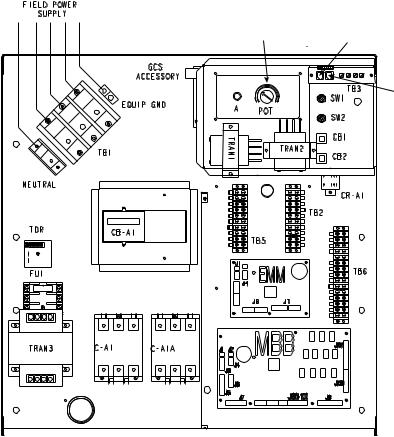
Table 1 — Terminal Block (TB) Locations Containing LEN Connector
UNIT MODEL |
LOCATION DESCRIPTION OF TB CONTAINING LEN CONNECTOR |
|
30HK,HL040-060 |
TB3 can be accessed without opening the control box door. It is located at the upper right corner |
|
of the control box. |
||
|
||
30HW018-040 |
TB3 can be accessed without opening the control box door. It is located at the upper right corner |
|
of the control box. |
||
|
||
30RB060-120 |
TB3 can be accessed by opening the control box door. It is located at the right side of the hinged |
|
display door. |
||
|
||
30RB130-300 |
TB3 can be accessed by opening the left hand (smaller) door of the fan control panel. It is |
|
located at the right side of the display panel. |
||
|
||
30RB315-390 |
Unit sizes 30RB315-390 are modular units and thus, accept two Navigator™ modules, one on |
|
each unit module. See Table 2. |
||
|
||
48PG03-16 (TB1) 48PG20-28 (TB2) |
Both TBs are accessed by opening the control box door. TB1 (PG03-16) or TB2 (PG20-28) is |
|
50PG03-16 (TB1) 50PG20-28 (TB2) |
located in the lower right of the control box. |
|
|
TB3 can be accessed by opening the control box door. It is located in the lower center of the |
|
48AJ,AK,AW,AY020-060 |
control box. |
|
50AJ,AK,AW,AY020-060 |
NOTE: If the unit is equipped with an Economizer Circuit Board (ECB), the ECB provides an |
|
|
auxiliary RJ14 LEN connector. See product documentation for more detail. |
|
|
TB3 can be accessed by opening the control box door. It is located to the left of the Scrolling |
|
48ZG,ZN,ZT,ZW,Z6,Z8 |
Marquee (display). |
|
50ZG,ZN,ZT,ZW,ZX,ZZ,Z2,Z3,Z6,Z7,Z8,Z9 |
NOTE: These units provide an auxiliary RJ14 LEN connection on the corner post on the enter- |
|
|
ing air end of the unit. See product documentation for more detail. |
Table 2 — 30RB315-390 Modular Unit Combinations
UNIT SIZE |
Module A |
Module B |
30RBA315 |
30RBA160 |
30RBA160 |
30RBA330 |
30RBA170 |
30RBA160 |
30RBA345 |
30RBA170 |
30RBA170 |
30RBA360 |
30RBA190 |
30RBA170 |
30RBA390 |
30RBA190 |
30RBA190 |
LEGEND FOR FIG. 2 - FIG. 8
A |
— Alarm |
AUX |
— Auxiliary |
C |
— Contactor, Compressor |
CAP |
— Capacitor |
CB |
— Circuit Breaker |
CB-FN — Circuit Breaker Fan Circuit |
|
CB-HT |
— Circuit Breaker Cooler Heater |
CB-P |
— Circuit Breaker Pump |
CCB |
— Control Circuit Board |
CCN |
— Carrier Comfort Network |
CLHR |
— Cooler Heater Relay |
CR |
— Control Relay |
CS |
— Current Sensor |
CSB |
— Current Sensor Board |
DS |
— Disconnect Switch |
ECB |
— Economizer Circuit Board |
EMM |
— Energy Management Module |
EQUIP |
— Equipment |
EXV |
— Electronic Expansion Valve |
EXVB |
— EXV Board |
FB |
— Fuse Block |
FB1 |
— Fan Board 1 |
FC |
— Fan Contactor |
GCS |
— Ground Current Sensing |
GND |
— Ground |
HACR |
— Heating, Air Conditioning, and Refrigeration |
IDR |
— Inducer Draft Relay |
IFC |
— Indoor Fan Contactor |
IFCB |
— Indoor Fan Circuit Breaker |
MMC |
— Motormaster® Contactor |
MMR |
— Motormaster Relay |
OFC |
— Outdoor Fan Contactor |
PLP |
— Phase Loss Protection |
RCB |
— Rooftop Control Board |
LEN |
— Local Equipment Network |
MBB |
— Main Base Board |
NEC |
— National Electrical Code |
PMP |
— Pump Contactor |
POT |
— Potentiometer |
RRB |
— Reverse Rotation Board |
SW |
— Switch |
TB |
— Terminal Block |
TDR |
— Time-Delay Relay |
TRAN |
— Transformer |
TXV |
— Thermostatic Expansion Value |
|
Terminal Block Connection |
|
Field Power Wiring |
|
Factory Wiring |
|
Field Wiring |
|
Accessory or Option Wiring |
|
To indicate common potential only, not to |
|
represent wiring |
2

SETPOINT POTENTIOMETER (EXPORT ONLY)
FIELD POWER SUPPLY
MARQUEE DISPLAY (DOMESTIC-STANDARD) (EXPORT-OPTIONAL)
SEE OTHER
LABELS
CCN
CONNECTIONS
NAVIGATOR
LEN
CONNECTION
ENABLE
ON/OFF
CONTACT SWITCH
EMERGENCY
ON/OFF
SWITCH
a30-4460
Fig. 2 — 30HK,HL040-060 Units Navigator™ LEN Connection
3
MARQUEE DISPLAY LOCATION
NAVIGATOR LEN CONNECTION
CCN
a30-
Fig. 3 — 30HW018-040 Units Navigator™ LEN Connection
4
 Loading...