


25HCR3C
Comfortt 13 Series Coastal Heat Pump with R---22 Refrigerant
1---1/2 to 5 Nominal Tons (Size 18 To 60)
Product Data
INDUSTRY LEADING
FEATURES / BENEFITS
EFFICIENCY
S 13 SEER/ 10.8 EER / 8.0 - 8.5 HSPF (nominal)
S Microtube Technologyt refrigeration system
S Indoor air quality accessories available
SOUND
S Sound level as low as 71 dBA
S Compressor sound blanket
COMFORT
S System supports Thermidistatt or standard thermostat controls
RELIABILITY
S Armor Platet coil fin corrosion protection
S Front-seating service valves
S Scroll compressor
S Internal pressure relief valve
S Internal thermal overload
S High and Low pressure switch
S Filter drier
S Balanced refrigeration system for maximum reliability
DURABILITY
WeatherArmort protection package:
S Solid, durable sheet metal construction
S Louvered coil guard
S Baked-on, complete coverage, powder paint
APPLICATIONS
S Long-line - up to 250 feet (76.20 m) total equivalent length, up to 200 feet (60.96 m) condenser above evaporator, or up to 60 ft. (18.29 m) evaporator above condenser (See Longline Guide for more information.)
S Low ambient (down to -20_F/-28.9_C) with accessory kit
WARRANTY
S 10 year limited compressor warranty / 5 yr parts

25HCR3C
MODEL NUMBER NOMENCLATURE
1 |
2 |
3 |
4 |
5 |
6 |
7 |
8 |
9 |
10 |
11 |
12 |
13 |
N |
N |
A |
A |
A/N |
N |
N |
N |
A/N |
A/N |
A/N |
N |
N |
2 |
5 |
H |
C |
R |
3 |
3 |
6 |
C |
0 |
0 |
3 |
0 |
Product |
Product |
Tier |
Major |
SEER |
Cooling |
Variations |
Open |
Open |
Voltage |
Minor |
||
Series |
|
Family |
Series |
Capacity |
Series |
|||||||
|
|
|
|
|
|
|
||||||
25 = HP |
H = RES HP |
C=Comfort |
R = R---22 |
3=13 SEER |
|
|
C = Coastal |
0=Not |
0=Not |
3=208/230---1 |
0, 1, 2... |
|
|
|
Defined |
Defined |
|||||||||
|
|
|
|
|
|
|
|
|
|
|
||
ISO 9001:2000
REGISTERED
This product has been designed and manufactured to meet Energy Star→ criteria for energy efficiency when matched with appropriate coil components. However, proper refrigerant charge and proper air flow are critical to achieve rated capacity and efficiency. Installation of this product should follow all manufacturing refrigerant
charging and air flow instructions. Failure to confirm proper charge and air flow may reduce energy efficiency and shorten equipment life.
STANDARD FEATURES
Feature |
18---30 |
24---30 |
30---30 |
36---30 |
48---30 |
60---30 |
|
|
|
|
|
|
|
13 SEER |
X |
X |
X |
X |
X |
X |
|
|
|
|
|
|
|
Scroll Compressor |
X |
X |
X |
X |
X |
X |
|
|
|
|
|
|
|
Louvered Coil Guard |
X |
X |
X |
X |
X |
X |
|
|
|
|
|
|
|
Field Installed Filter Drier |
X |
X |
X |
X |
X |
X |
|
|
|
|
|
|
|
Front Seating Service Valves |
X |
X |
X |
X |
X |
X |
|
|
|
|
|
|
|
Internal Pressure Relief Valve |
X |
X |
X |
X |
X |
X |
|
|
|
|
|
|
|
Internal Thermal Overload |
X |
X |
X |
X |
X |
X |
|
|
|
|
|
|
|
Long Line capability |
X |
X |
X |
X |
X |
X |
|
|
|
|
|
|
|
Low Ambient capability with Kit |
X |
X |
X |
X |
X |
X |
|
|
|
|
|
|
|
High Pressure Switch |
X |
X |
X |
X |
X |
X |
|
|
|
|
|
|
|
Loss of Charge Pressure Switch |
X |
X |
X |
X |
X |
X |
|
|
|
|
|
|
|
ArmorPlatet Condenser Coil Protection |
X |
X |
X |
X |
X |
X |
|
|
|
|
|
|
|
Accumulator |
X |
X |
X |
X |
X |
X |
|
|
|
|
|
|
|
2

PHYSICAL DATA
UNIT SIZE---SERIES, VOLTAGE |
18---30 |
24---30 |
30---30 |
|
36---30 |
|
42---30 |
48---30 |
60---30 |
Operating Weight lb (kg) |
207 |
204 |
211 |
|
252 |
|
239 |
314 |
361 |
(93.9) |
(92.5) |
(95.7) |
|
(114.3) |
|
(108.4) |
(142.4) |
(163.8) |
|
|
|
|
|||||||
Shipping Weight lb (kg) |
218 |
236 |
222 |
|
287 |
|
250 |
348 |
395 |
(98.9) |
(107.1) |
(100.7) |
|
(130.2) |
|
(113.4) |
(157.9) |
(179.2) |
|
|
|
|
|||||||
Compressor Type |
|
|
|
|
Scroll |
|
|
|
|
REFRIGERANT |
|
|
Freon (R---22) |
|
|
|
|||
Control |
|
|
TXV (R---22 Hard Shutoff) |
|
|
|
|||
Charge lb (kg) |
7 |
7 |
6.8 |
|
8.1 |
|
9.5 |
13.5 |
16.5 |
(3.2) |
(3.2) |
(3.1) |
|
(3.7) |
|
(4.3) |
(6.1) |
(7.5) |
|
|
|
|
|||||||
COND FAN |
|
|
|
|
|
|
|
|
|
Air Discharge |
|
|
|
|
Vertical |
|
|
|
|
Air Qty (CFM) |
2233 |
2614 |
3167 |
|
3334 |
|
3334 |
4046 |
4046 |
Motor HP |
1/12 |
1/10 |
1/5 |
|
1/8 |
|
1/8 |
1/4 |
1/4 |
Motor RPM |
800 |
800 |
800 |
|
800 |
|
800 |
800 |
800 |
COND COIL |
|
|
|
|
|
|
|
|
|
Face Area (Sq ft) |
19.4 |
21.56 |
19.40 |
|
25.15 |
|
17.60 |
25.15 |
30.18 |
Fins per In. |
20 |
20 |
20 |
|
20 |
|
20 |
20 |
20 |
Rows |
1 |
1 |
1 |
|
1 |
|
2 |
2 |
2 |
Circuits |
5 |
6 |
6 |
|
6 |
|
8 |
8 |
11 |
VALVE CONNECT. (In.) ID |
|
|
|
|
|
|
|
|
|
Vapor |
5/8” |
5/8” |
3/4” |
|
3/4” |
|
7/8” |
7/8” |
7/8” |
Liquid |
|
|
|
|
3/8” |
|
|
|
|
REFRIGERANT TUBES* (in.)OD |
|
|
|
|
|
|
|
|
|
Vapor (0---80 Ft Tube Length) |
5/8” |
5/8” |
3/4” |
|
3/4” |
|
7/8” |
7/8” |
1---1/8 |
Liquid (0---80 Ft Tube Length) |
|
|
|
|
3/8” |
|
|
|
|
* For tubing sets between 80 and 200 ft. horizontal or 20 ft. vertical differential, consult the Longline Guideline. Note: See unit Installation Instruction for proper installation.
VAPOR LINE SIZING AND COOLING CAPACITY LOSS 1-STAGE HEAT PUMP APPLICATIONS
LONG LINE APPLICATION: An application is considered ”Long |
|
when outdoor unit is above indoor unit, and 60 ft. (18.29 m) when |
||||||||||||
line” when the total equivalent tubing length exceeds 80 ft. (24.38 |
|
the outdoor unit is below the indoor unit. Refer to Accessory |
||||||||||||
m) or when there is more than 20 ft. (6.09 m) vertical separation |
|
Usage Guideline below for required accessories. See Longline |
||||||||||||
between indoor and outdoor units. These applications require |
|
Application Guideline for required piping and system |
||||||||||||
additional accessories and system modifications for reliable system |
|
modifications. Also, refer to the table below for the acceptable |
||||||||||||
operation. The maximum allowable total equivalent length is 250 |
|
vapor tube diameters based on the total length to minimize the |
||||||||||||
ft. (76.2 m). The maximum vertical separation is 200 ft. (60.96 m) |
|
cooling capacity loss. |
|
|
|
|
||||||||
|
|
|
|
|
|
|
|
|
|
|
|
|
|
|
|
Acceptable |
|
|
|
|
|
Cooling Capacity Loss (%) |
|
|
|
|
|||
Unit Nominal |
|
|
|
|
Total Equivalent Line Length ft. (m) |
|
|
|
|
|||||
Vapor Line |
|
|
|
|
|
|
|
|
|
|
|
|
|
|
Standard Application |
|
|
Long Line Application Requires Accessories |
|
||||||||||
Size (Btuh) |
Diameters |
|
|
|
||||||||||
|
(In.) OD |
25 |
50 |
80 |
80+ |
|
100 |
125 |
150 |
|
175 |
200 |
225 |
250 |
|
|
(7.62) |
(15.24) |
(24.38) |
(24.38+) |
|
(30.48) |
(38.10) |
(45.72) |
|
(53.34) |
(60.96) |
(68.58) |
(76.2) |
18,000 |
5/8 |
0 |
1 |
1 |
1 |
|
2 |
3 |
3 |
|
4 |
5 |
5 |
6 |
R---22 HP |
3/4 |
0 |
0 |
0 |
0 |
|
0 |
1 |
1 |
|
1 |
1 |
2 |
2 |
24,000 |
5/8 |
0 |
1 |
3 |
3 |
|
3 |
5 |
6 |
|
7 |
8 |
9 |
10 |
3/4 |
0 |
0 |
0 |
0 |
|
1 |
1 |
1 |
|
2 |
2 |
3 |
3 |
|
R---22 HP |
|
|
||||||||||||
7/8 |
0 |
0 |
0 |
0 |
|
0 |
0 |
0 |
|
0 |
1 |
1 |
1 |
|
|
|
|
||||||||||||
30,000 |
5/8 |
1 |
3 |
5 |
5 |
|
6 |
8 |
10 |
|
11 |
13 |
15 |
17 |
3/4 |
0 |
1 |
1 |
1 |
|
2 |
3 |
3 |
|
4 |
5 |
5 |
6 |
|
R---22 HP |
|
|
||||||||||||
7/8 |
0 |
0 |
0 |
0 |
|
1 |
1 |
1 |
|
2 |
2 |
2 |
3 |
|
|
|
|
||||||||||||
36,000 |
3/4 |
0 |
1 |
2 |
2 |
|
3 |
4 |
5 |
|
6 |
7 |
8 |
9 |
R---22 HP |
7/8 |
0 |
0 |
1 |
1 |
|
1 |
2 |
2 |
|
3 |
3 |
4 |
4 |
42,000 |
3/4 |
1 |
2 |
3 |
3 |
|
4 |
5 |
7 |
|
8 |
9 |
10 |
11 |
R---22 HP |
7/8 |
0 |
1 |
1 |
1 |
|
2 |
2 |
3 |
|
4 |
4 |
5 |
5 |
48,000 |
3/4 |
1 |
2 |
4 |
4 |
|
5 |
7 |
8 |
|
10 |
11 |
13 |
14 |
7/8 |
0 |
1 |
2 |
2 |
|
2 |
3 |
4 |
|
5 |
5 |
6 |
7 |
|
R---22 HP |
|
|
||||||||||||
1---1/8 |
0 |
0 |
0 |
0 |
|
0 |
0 |
1 |
|
1 |
1 |
1 |
1 |
|
|
|
|
||||||||||||
60,000 |
7/8 |
1 |
2 |
3 |
3 |
|
4 |
5 |
7 |
|
8 |
9 |
10 |
11 |
R---22 HP |
1---1/8 |
0 |
0 |
1 |
1 |
|
1 |
1 |
2 |
|
2 |
2 |
3 |
3 |
|
|
|
|
|
|
|
|
|
|
|
|
|
|
|
Standard Length = 80 ft. (24.38 m) or less total equivalent length
Applications in this area are long line. Accessories are required as shown recommended on Long Line Application Guidelines
Applications in this area may have height restrictions that limit allowable total equivalent length, when outdoor unit is below indoor unit See Long Line Application Guidelines
25HCR3C
3
25HCR3C
ACCESSORY THERMOSTATS
|
THERMOSTAT / SUBBASE PKG. |
DESCRIPTION |
|
|
||
|
|
|
|
Thermidistatt Control — Non---Programmable/Programmable Thermostat with |
||
TSTATCCPRH01--- |
B* |
Humidity Control (For use in Dual Fuel, AC, HP, and 2S applications. Includes Out- |
||||
|
|
|
|
door Air Temperature Sensor.) |
|
|
TSTATCCPHH01 |
B* |
HybridHeatt (Dual Fuel) Thermostat — Auto Changeover, 7--- |
Day Programmable, |
|||
°F/°C, Includes Outdoor Sensor (TSTATXXSEN01 B) |
|
|
||||
|
|
|
|
|
|
|
TSTATCCPHP01 |
B |
Thermostat — Auto Changeover, 7---Day Programmable, °F/°C, 2 |
---Stage Heat, |
|||
1 Stage Cool |
|
|
||||
|
|
|
|
|
|
|
TSTATCCNHP01 |
C |
Thermostat — Auto Changeover, Non---Programmable, °F/°C, 2--- |
Stage Heat, |
|||
1 Stage Cool |
|
|
||||
|
|
|
|
|
|
|
TSTATCCSHP01 |
|
Standard Programmable Thermostat—Manual Changeover, 5--- |
2 Day Program- |
|||
|
mable, °F/°C, 1 Stage Heat/ 1 Stage Cool |
|
|
|||
|
|
|
|
|
|
|
TSTATCCBHP01* |
B |
Builder’s Thermostat — Heat Pump, Non---Programmable, °F/°C, 2 Stage Heat,--- |
||||
1 Stage Cool, Manual Changeover |
|
|
||||
|
|
|
|
|
|
|
TSTATXXSEN01--- |
B** |
Outdoor Air Temperature Sensor |
|
|
||
TSTATXXNBP01 |
|
Backplate for Non---Programmable Thermostat |
|
|
||
TSTATXXPBP01 |
|
Backplate for Programmable Thermostat and Thermidistatt Control |
||||
TSTATXXSBP01 |
|
Backplate for Standard Programmable Thermostat |
|
|
||
TSTATXXBBP01 |
|
Backplate for Builder’s Thermostat |
|
|
||
TSTATXXCNV10{ |
|
Thermostat Conversion Kit (4 to 5 Wire) — 10 Pack |
|
|
||
TP--- |
PRH--- |
01 |
|
Performance Series Programmable Thermidistat |
|
|
|
|
|
|
|
|
|
TP--- |
NRH--- |
01 |
|
Performance Series Non---programmable Thermidistat |
|
|
|
|
|
|
|
|
|
TP--- |
PHP--- |
01 |
|
Performance Series Programmable HP Stat |
|
|
|
|
|
|
|
|
|
TP--- |
NHP--- |
01 |
|
Performance Series Non---programmable HP Stat |
|
|
|
|
|
|
|
|
|
TC--- |
PHP--- |
01 |
|
Comfort Series Programmable HP Stat |
|
|
|
|
|
|
|
|
|
TC--- |
NHP--- |
01 |
|
Comfort Series Non---programmable HP Stat |
|
|
|
|
|
|
|
|
|
TB--- |
PHP--- |
01 |
|
Base Series Programmable HP Stat |
|
|
|
|
|
|
|
|
|
TB--- |
NHP--- |
01 |
|
Base Series Non---programmable HP Stat |
|
|
*Do not use in zoning heat pump applications.
**Outdoor temperature sensor is an accessory for all Carrier electronic thermostats, except the non---programmable air conditioner version and builder;s thermostats. It allows the temperature at a remote location (outdoors) to be displayed on the thermostat. The outdoor air temperature sensor must be used with the HybridHeatt (dual fuel) thermostat.
{Thermostat conversion kit is a 24---vac accessory that can turn a 4---wire thermostat application into a 5---wire application. This kit can also be used to replace a broken thermostat wire, or add an extra wire when needed.
The outdoor air temperature sensor is included with the Thermidistat Control and HybridHeatt (dual fuel) thermostat.
ACCESSORIES
ORDER NUMBER |
DESCRIPTION |
18---30 |
24---30 |
30---30 |
36---30 |
42---30 |
48---30 |
60---30 |
HC32GE229 |
BALL BEARING MOTOR |
X |
|
|
|
|
|
|
HC34GE242 |
BALL BEARING MOTOR |
|
X |
|
|
|
|
|
HC36GE232 |
BALL BEARING MOTOR |
|
|
|
X |
X |
|
|
HC38GE228 |
BALL BEARING MOTOR |
|
|
X |
|
|
|
|
HC40GE228 |
BALL BEARING MOTOR |
|
|
|
|
|
X |
X |
KAACH1201AAA |
CRANKCASE HTR |
|
|
|
X |
|
S |
S |
KAACH1401AAA |
CRANKCASE HTR |
|
X |
|
|
|
|
|
KAACH1601AAA |
CRANKCASE HTR |
|
|
X |
|
X |
|
|
KAACH1701AAA |
CRANKCASE HTR |
X |
X |
|
|
|
|
|
KAAFT0101AAA |
FREEZE THERMOSTAT |
X |
X |
X |
X |
X |
X |
X |
KSAHS1501AAA |
HARD START |
X |
X |
X |
X |
X |
X |
|
KSAHS1601AAA |
HARD START |
|
|
|
|
|
|
X |
KHAIR0101AAA |
ISOLATION RELAY |
X |
X |
X |
X |
X |
X |
X |
KSACY0101AAA |
CYCLE PROTECTOR |
X |
X |
X |
X |
X |
X |
X |
KSALA0201R22 |
LOW AMBIENT |
X |
X |
X |
X |
X |
X |
X |
KSALA0601AAA |
MOTORMASTER 230V |
X |
X |
X |
X |
X |
X |
X |
KHAOT0201SEC |
OUTDOOR THERMOSTAT |
X |
X |
X |
X |
X |
X |
X |
KHAOT0301FST |
OUTDOOR THERMOSTAT |
X |
X |
X |
X |
X |
X |
X |
KHASS0606MPK |
SNOW STAND |
X |
X |
X |
X |
X |
X |
X |
KHALS0401LLS |
SOLENOID VALVE |
X |
X |
X |
X |
X |
X |
X |
KAACS0201PTC |
START ASSIST PTC |
X |
X |
X |
X |
X |
X |
X |
KSASF0101AAA |
SUPPORT FEET |
X |
X |
X |
X |
X |
X |
X |
KAATD0101TDR |
TIME DELAY |
X |
X |
X |
X |
X |
X |
X |
KSATX0601HSO |
TXV |
X |
X |
X |
X |
X |
|
|
KSATX0701HSO |
TXV |
|
|
|
|
|
X |
|
KSATX1001HSO |
TXV |
|
|
|
|
|
|
X |
X = Accessory S = Standard |
|
|
|
|
|
|
|
|
4

ACCESSORY USAGE GUIDELINE
|
REQUIRED FOR |
REQUIRED FOR LONG |
REQUIRED FOR SEA |
|
Accessory |
LOW---AMBIENT APPLICATIONS |
LINE APPLICATIONS* |
COAST APPLICATIONS |
|
|
(Below 55° F / 12.78° C) |
(Over 80 Ft. / 24.38 m) |
(Within 2 miles / 3.22 km) |
|
Ball Bearing Fan Motor |
Yes{ |
No |
No |
|
Compressor Start Assist |
Yes{ |
Yes |
No |
|
Capacitor and Relay |
||||
|
|
|
||
Crankcase Heater |
Yes{ |
Yes |
No |
|
Evaporator Freeze Thermostat |
Yes{ |
No |
No |
|
Isolation Relay |
Yes{ |
No |
No |
|
Liquid Line Solenoid Valve |
No |
See Long Line Application |
No |
|
Guideline |
||||
|
|
|
||
Motor Master→ Control |
Yes{ |
No |
No |
|
or Low---ambient Pressure Switch |
||||
|
|
|
||
Support Feet |
Recommended |
No |
Recommended |
*For tubing line sets between 80 and 200 ft. (24.38 and 60.96 m) and/or 20 ft. vertical (6.09 m) differential, refer to Residential Split System Long Line Application Guideline.
{ Required for Low---Ambient Controller MotorMasterr Control only.
Accessory Description and Usage (Listed Alphabetically)
1. Ball-Bearing Fan Motor
A fan motor with ball bearings which permits speed reduction while maintaining bearing lubrication.
Usage Guideline:
Required on all units when MotorMasterr is used.
2. Compressor Start Assist - Capacitor and Relay
Start capacitor and relay gives a ”hard” boost to compressor motor at each start up.
Usage Guideline:
Required for reciprocating compressors in the following applications:
Long line
Low ambient cooling
Hard shut off expansion valve on indoor coil Liquid line solenoid on indoor coil
Required for single-phase scroll compressors in the following applications:
Long line
Low ambient cooling
Suggested for all compressors in areas with a history of low voltage problems.
3. Compressor Start Assist — PTC Type
Solid state electrical device which gives a ”soft” boost to the compressor at each start-up.
Usage Guideline:
Suggested in installations with marginal power supply.
4. Crankcase Heater
An electric resistance heater which mounts to the base of the compressor to keep the lubricant warm during off cycles. Improves compressor lubrication on restart and minimizes the chance of liquid slugging.
Usage Guideline:
Required in low ambient cooling applications. Required in long line applications.
Suggested in all commercial applications.
5. Cycle Protector
The cycle protector is designed to prevent compressor short cycling. This control provides an approximate 5-minute delay after power to the compressor has been interrupted for any reason, including power outage, protector control trip, thermostat jiggling, or normal cycling.
6. Evaporator Freeze Thermostat
An SPST temperature-actuated switch that stops unit operation when evaporator reaches freeze-up conditions.
Usage Guideline:
Required when low ambient kit has been added.
7. High Pressure Switch
A high pressure switch that protects unit against excessive pressure. Usage Guideline:
Required in all heat pumps operated in dual fuel applications.
8. Isolation Relay
An SPDT relay which switches the low-ambient controller out of the outdoor fan motor circuit when the heat pump switches to heating mode.
Usage Guideline:
Required in all heat pumps where low ambient kit has been added.
9. Liquid-Line Solenoid Valve (LLS)
An electrically operated shutoff valve which stops and starts refrigerant liquid flow in response to compressor operation. It is to be installed at the outdoor unit to control refrigerant off cycle migration in the heating mode.
Usage Guideline:
An LLS is required in all long line heat pump applications to control refrigerant off cycle migration in the heating mode. See Long Line Guideline.
10. Low-Ambient Pressure Switch Kit
A long life pressure switch which is mounted to outdoor unit service valve. It is designed to cycle the outdoor fan motor in order to maintain head pressure within normal operating limits (approximately 100 psig to 225 psig). The control will maintain working head pressure at low-ambient temperatures down to 0_F/-17.78_C when properly installed.
Usage Guideline:
A Low-Ambient Pressure Switch or MotorMasterr Low-Ambient Controller must be used when cooling operation is used at outdoor temperatures below 55_F (12.8_C).
25HCR3C
5

25HCR3C
Accessory Description and Usage (Listed Alphabetically) - CONTINUED
11. MotorMasterr Low-Ambient Controller
A fan-speed control device activated by a temperature sensor, designed to control condenser fan motor speed in response to the saturated, condensing temperature during operation in cooling mode only. For outdoor temperatures down to -20_F (-28.9_C), it maintains condensing temperature at 100_F ±10_F (37.8_C ± 5.5_C).
Usage Guideline:
A MotorMasterr Low Ambient Controller or Low-Ambient Pressure Switch must be used when cooling operation is used at outdoor temperatures below 55_F (12.8_C).
Suggested for all commercial applications.
12. Outdoor Air Temperature Sensor
Designed for use with Carrier Thermostats listed in this publication. This device enables the thermostat to display the outdoor temperature. This device also is required to enable special thermostat features such as auxiliary heat lock out.
Usage Guideline:
Suggested for all Carrier thermostats listed in this publication.
13. Outdoor Thermostat
An SPDT temperature-actuated switch which turns on supplemental electric heaters when outdoor air temperature drops below a user-selected set point.
Usage Guideline:
Electric supplemental heat applications in non-variable speed indoor units when electric heat staging is desired.
Usage Guideline:
Some local codes may require limiting the heating head pressure in the vapor line in some applications.
14. Secondary Outdoor Thermostat
An SPDT temperature-actuated switch which turns on third-stage of supplemental electric heaters when outdoor air temperature drops below the second-stage set point.
Usage Guideline:
Outdoor thermostat applications where electric heater is capable of 3-stage operation.
15. Snow Stand
Coated wire rack which supports unit 18 in. (457.2 mm) above mounting pad to allow for drainage from unit base.
Usage Guideline:
Suggested in the following applications:
Heat pump installations in heavy snowfall areas. Heat pump installations in snow drift locations.
Heat pump installations in areas of prolonged subfreezing temperatures.
All commercial installations.
16. Sound Hood
Wraparound sound reducing cover for the compressor. Reduces the sound level up to 2 dBA.
Usage Guideline:
Suggested when unit is installed closer than 15 ft (4.57 m) to quiet areas, bedrooms, etc.
Suggested when unit is installed between two houses less than 10 ft (3.05 m) apart.
Usage Guideline:
Suggested in the following applications:
Heat pump installations in heavy snowfall areas. Heat pump installations in snowdrift locations.
Heat pump installations in areas of prolonged subfreezing temperatures.
All commercial installations.
17. Thermostatic Expansion Valve (TXV) Bi-Flow
A modulating flow-control valve which meters refrigerant liquid flow rate into the evaporator in response to the superheat of the refrigerant gas leaving the evaporator.
Usage Guideline:
Required in all heat pump applications
18. Time-Delay Relay
An SPST delay relay which briefly continues operation of indoor blower motor to provide additional cooling after the compressor cycles off.
Note: Most indoor unit controls include this feature. For those that do not, use the guideline below.
Usage Guideline:
Accessory required to meet ARI rating, where indoor not equipped.
6

ELECTRICAL DATA
|
|
|
|
|
|
|
|
|
|
|
MIN |
MIN |
MAX |
MAX |
MAX |
UNIT SIZE |
V/PH |
OPER VOLTS* |
COMPR |
FAN |
MCA |
WIRE |
WIRE |
LENGTH |
LENGTH |
FUSE** |
|||||
|
|
|
|
|
|
|
SIZE† |
SIZE† |
ft.(m)‡ |
ft.(m)‡ |
or BRK |
||||
|
|
|
|
|
|
|
|
|
|
||||||
|
|
MAX |
|
MIN |
LRA |
|
RLA |
FLA |
|
60˚ C |
75˚ C |
60˚ C |
75˚ C |
AMPS |
|
18 |
|
|
|
|
41 |
|
9.8 |
0.5 |
12.7 |
|
14 |
14 |
124 |
118 |
20 |
|
|
|
|
|
|
(37.80) |
(35.97) |
||||||||
|
|
|
|
|
|
|
|
|
|
|
|
|
|
||
24 |
|
|
|
|
54 |
|
15.13 |
0.7 |
19.6 |
|
14 |
14 |
80 |
76 |
30 |
|
|
|
|
|
|
(23.16) |
(23.16) |
||||||||
|
|
|
|
|
|
|
|
|
|
|
|
|
|
||
30 |
|
|
|
|
72.5 |
|
13.50 |
1.2 |
18.6 |
|
14 |
14 |
85 |
81 |
30 |
|
|
|
|
|
|
(25.91) |
(24.69) |
||||||||
|
|
|
|
|
|
|
|
|
|
|
|
|
|
||
36 |
208/230/1---60 |
253 |
|
197 |
88 |
|
18.68 |
0.9 |
24.2 |
|
12 |
12 |
103| |
98 |
40 |
|
|
|
(31.39) |
(29.87) |
|||||||||||
|
|
|
|
|
|
|
|
|
|
|
|
|
|
||
42 |
|
|
|
|
104 |
|
17.90 |
0.9 |
24.0 |
|
12 |
12 |
104 |
99 |
40 |
|
|
|
|
|
|
(31.70) |
(30.18) |
||||||||
|
|
|
|
|
|
|
|
|
|
|
|
|
|
||
48 |
|
|
|
|
137 |
|
22.22 |
1.2 |
29.0 |
|
10 |
10 |
138 |
131 |
50 |
|
|
|
|
|
|
(42.06) |
(39.93) |
||||||||
|
|
|
|
|
|
|
|
|
|
|
|
|
|
||
60 |
|
|
|
|
148 |
|
28.85 |
1.2 |
37.3 |
|
8 |
8 |
167 |
159 |
60 |
|
|
|
|
|
|
(50.90) |
(48.46) |
||||||||
|
|
|
|
|
|
|
|
|
|
|
|
|
|
||
* Permissible limits of the voltage range at which the unit will operate satisfactorily |
|
|
|
|
|
|
|
||||||||
{ If wire is applied at ambient greater than 30° C, consult table 310 |
---16 of the NEC (ANSI/NFPA 70). The ampacity of non metallic--- sheathed--- cable (NM), |
||||||||||||||
trade name ROMEX, shall be that of 60° C |
conditions, per the NEC (ANSI/NFPA 70) Article 336 |
---26. If other than uncoated (no--- |
plated), 60 or 75° C |
||||||||||||
insulation, copper wire (solid wire for 10 AWG or smaller, stranded wire for larger than 10 AWG) is used, consult applicable tables of the NEC (ANSI/NFPA 70).
} Length shown is as measured 1 way along wire path between unit and service panel for voltage drop not to exceed 2%. ** Time---Delay fuse.
FLA --- Full Load Amps LRA --- Locked Rotor Amps
MCA--- Minimum Circuit Amps RLA --- Rated Load Amps
NOTE: Control circuit is 24---V on all units and requires external power source. Copper wire must be used from service disconnect to unit. All motors/compressors contain internal overload protection.
A-WEIGHTED SOUND LEVEL (dBA)
|
STANDARD |
TYPICAL OCTAVE BAND SPECTRUM (dB, without tone adjustment) |
|||||||
UNIT SIZE |
RATING |
||||||||
|
|
|
|
|
|
|
|||
|
(dB) |
125 |
250 |
500 |
1000 |
2000 |
4000 |
8000 |
|
|
|
|
|
|
|
|
|
|
|
18 |
71 |
55 |
58 |
64.5 |
65 |
64.5 |
63 |
55.5 |
|
24 |
74 |
57.0 |
62.5 |
68.5 |
69.5 |
67.5 |
63.0 |
55.0 |
|
30 |
73 |
58.0 |
66.0 |
66.0 |
67.5 |
64.5 |
61.0 |
54.5 |
|
36 |
74 |
53.5 |
65.5 |
64.5 |
68.5 |
66.0 |
62.0 |
54.5 |
|
42 |
74 |
59.0 |
62.0 |
66.0 |
69.0 |
65.0 |
60.0 |
51.5 |
|
48 |
75 |
54.5 |
61.0 |
66.0 |
71.0 |
65.5 |
62.0 |
56.5 |
|
60 |
75 |
56.5 |
66.5 |
67.5 |
69.5 |
67.5 |
63.5 |
56.5 |
|
CHARGING SUBCOOLING (TXV-TYPE EXPANSION DEVICE)
UNIT SIZE---SERIES |
REQUIRED SUBCOOLING _F (_C) |
Heating Piston Size |
|
18 |
10 (5.6) |
42 |
|
24 |
10 (5.6) |
52 |
|
30 |
10 (5.6) |
57 |
|
36 |
10 (5.6) |
57 |
|
42 |
10 (5.6) |
67 |
|
48 |
9 |
(5.0) |
67 |
60 |
10 (5.6) |
78 |
|
25HCR3C
7
25HCR3C
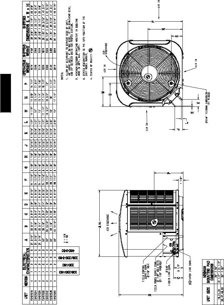
DIMENSIONS
8

|
|
|
|
|
|
|
|
I |
|
|
|
|
|
|
|
|
|
|
|
R |
|
|
|
|
|
|
|
|
25HCR3C BALANCE POINT WORKSHEET |
|
|
|
|
|
|
|
HEATING |
|
80.00 |
|
|
|
|
|
|
23.4 |
|
|
|
|
70.00 |
|
|
|
|
25HCR360C |
|
20.5 |
|
|
|
|
|
|
|
|
|
FC4DN(F,B)060 |
|
|
|
|
|
|
60.00 |
|
|
|
|
25HCR348C |
|
17.6 |
|
|
INTEGRATEDUNITLOSS,HEAT |
MBTUHCAPACITY, |
|
|
|
|
FC4DN(F,B)048 |
|
|||
9 |
|
|
|
|
|
25HCR342C |
|
|
kW |
||
|
|
|
50.00 |
|
|
|
|
FC4DN(F,B)042 |
14.6 |
|
|
|
|
|
40.00 |
|
|
|
|
25HCR336C |
|
11.7 |
|
|
|
|
|
|
|
|
FC4DN(F,B)036 |
|
|||
|
|
|
|
|
|
|
|
25HCR330C |
|
|
|
|
|
|
|
|
|
|
|
FC4DNF030 |
|
|
|
|
|
|
30.00 |
|
|
|
|
25HCR324C |
|
8.8 |
|
|
BUILDING |
|
|
|
|
|
FA4CN(F,C)024 |
|
|||
|
|
20.00 |
|
|
|
|
25HCR318C |
|
5.9 |
|
|
|
|
|
|
|
|
|
|
|
|
|
|
|
|
|
|
|
|
|
|
FA4CN(F,C)018 |
|
|
|
|
|
|
10.00 |
|
|
|
BASED ON INDOOR ENT. A |
2.9 |
|
||
|
|
|
|
|
|
|
|
|
|||
|
|
|
|
|
|
|
AT 70 ºF AND AT RATED CFM |
|
|
||
|
|
|
0.00 |
|
|
|
|
|
|
0.0 |
|
|
|
|
--10 (23) |
0 (--17.78) |
10 (--12.22) 20 (--6.67) 30 (--1.11) 40 (4.44) |
50 (10) |
60 (15.56) |
70 (21.11) |
80 (26.67) |
||
|
|
|
|
|
OUTDOOR TEMPERATURE, _F (_C) |
|
|
|
|
|
|
25HCR3C

25HCR3C
COMBINATION RATINGS
Unit |
|
|
|
|
|
|
ARI Standard Ratings |
|
|
|
|
|
||
|
Cooling |
|
Cooling |
|
|
|
|
|
Heating |
|
|
|
||
Size --- |
Indoor Model |
|
|
|
|
|
|
|
|
|
||||
Voltage, |
Capa- |
Factory |
Standard |
SEER |
|
High Temp |
|
Low Temp |
|
|
Furnace Model |
|||
|
city |
EER |
|
|
|
|
|
|
HSPF |
|||||
Series |
|
Enhance |
Rating |
TDR |
E |
E |
|
H |
|
H |
|
|||
|
|
|
|
Capacity |
COP |
|
Capacity |
|
COP |
|
|
|||
|
|
|
|
|
|
|
|
|
|
|
||||
|
*FA4CN(F,C)018 |
17,000 |
TDR&TXV |
13.00 |
|
10.80 |
18,000 |
3.40 |
|
10,500 |
|
2.30 |
7.7 |
|
|
FA4CN(F,C)024 |
17,000 |
TDR&TXV |
13.00 |
|
10.80 |
17,300 |
3.30 |
|
10,600 |
|
2.28 |
7.7 |
|
|
FC4DNF018 |
17,300 |
TDR&TXV |
14.50 |
|
12.00 |
17,600 |
3.62 |
|
10,100 |
|
2.46 |
8.2 |
|
|
FC4DNF024 |
17,500 |
TDR&TXV |
14.50 |
|
12.50 |
16,800 |
3.58 |
|
10,100 |
|
2.48 |
8.2 |
|
|
FF1ENE018 |
16,900 |
TDR&TXV |
13.00 |
|
10.80 |
18,000 |
3.40 |
|
10,500 |
|
2.28 |
7.7 |
|
|
FF1ENE024 |
17,100 |
TDR&TXV |
13.00 |
|
10.80 |
17,100 |
3.36 |
|
10,500 |
|
2.32 |
7.7 |
|
|
FK4DNF001 |
17,300 |
TDR&TXV |
15.00 |
|
12.50 |
16,400 |
3.52 |
|
9,900 |
|
2.46 |
8.2 |
|
|
FK4DNF002 |
17,500 |
TDR&TXV |
15.00 |
|
12.50 |
16,400 |
3.64 |
|
9,900 |
|
2.50 |
8.4 |
|
|
|
|
|
|
|
|
|
|
|
|
|
|
|
|
|
CAR**1814A** |
16,700 |
TDR&TXV |
14.50 |
|
12.00 |
17,400 |
3.38 |
|
9,900 |
|
2.38 |
7.7 |
58CV(A,X)070---12 |
|
|
|
|
|
|
|
|
|
|
|
|
|
|
|
|
CAR**2414A** |
17,100 |
TDR&TXV |
14.50 |
|
12.50 |
17,100 |
3.56 |
|
9,900 |
|
2.44 |
8.0 |
58CV(A,X)070---12 |
|
CAR**2414A** |
17,200 |
TXV |
|
13.00 |
10.80 |
17,200 |
3.38 |
|
10,500 |
|
2.32 |
7.7 |
|
|
|
|
|
|
|
|
|
|
|
|
|
|
|
|
|
CAR**2417A** |
17,200 |
TDR&TXV |
14.50 |
|
12.50 |
17,100 |
3.58 |
|
9,900 |
|
2.46 |
8.2 |
58CV(A,X)090---16 |
|
CAR**2417A** |
17,200 |
TDR&TXV |
14.50 |
|
12.50 |
17,100 |
3.56 |
|
9,900 |
|
2.44 |
8.2 |
58MVB060---14 |
|
CAR**2417A** |
17,200 |
TDR&TXV |
14.50 |
|
12.50 |
17,100 |
3.56 |
|
9,900 |
|
2.44 |
8.2 |
58UVB060---14 |
|
CAR**2417A** |
17,200 |
TXV |
|
13.00 |
10.80 |
17,200 |
3.38 |
|
10,500 |
|
2.32 |
7.7 |
|
|
|
|
|
|
|
|
|
|
|
|
|
|
|
|
|
CNRF*2418A** |
17,300 |
TXV |
|
13.20 |
11.00 |
17,400 |
3.46 |
|
10,600 |
|
2.34 |
7.7 |
|
|
|
|
|
|
|
|
|
|
|
|
|
|
|
|
|
CNRH*2417A** |
17,200 |
TDR&TXV |
14.50 |
|
12.50 |
17,500 |
3.66 |
|
9,900 |
|
2.44 |
8.2 |
58CV(A,X)070---12 |
18---30 |
CNRH*2417A** |
17,300 |
TDR&TXV |
14.50 |
|
12.50 |
17,400 |
3.68 |
|
10,000 |
|
2.46 |
8.2 |
58CV(A,X)090---16 |
|
CNRH*2417A** |
17,200 |
TDR&TXV |
14.50 |
|
12.50 |
17,400 |
3.66 |
|
9,900 |
|
2.44 |
8.2 |
58MVB040---14 |
|
CNRH*2417A** |
17,200 |
TDR&TXV |
14.50 |
|
12.50 |
17,500 |
3.68 |
|
9,900 |
|
2.44 |
8.2 |
58MVB060---14 |
|
CNRH*2417A** |
17,300 |
TDR&TXV |
14.50 |
|
12.50 |
17,400 |
3.68 |
|
10,000 |
|
2.46 |
8.2 |
58MVB080---14 |
|
CNRH*2417A** |
17,300 |
TXV |
|
13.20 |
11.00 |
17,400 |
3.46 |
|
10,600 |
|
2.34 |
7.7 |
|
|
|
|
|
|
|
|
|
|
|
|
|
|
|
|
|
CNRV*1814A** |
17,100 |
TDR&TXV |
14.50 |
|
12.00 |
17,700 |
3.58 |
|
9,900 |
|
2.42 |
8.0 |
58CV(A,X)070---12 |
|
CNRV*1814A** |
17,100 |
TXV |
|
13.00 |
10.80 |
17,800 |
3.46 |
|
10,500 |
|
2.32 |
7.7 |
|
|
|
|
|
|
|
|
|
|
|
|
|
|
|
|
|
CNRV*2414A** |
17,200 |
TDR&TXV |
14.50 |
|
12.50 |
17,500 |
3.66 |
|
9,900 |
|
2.44 |
8.2 |
58CV(A,X)070---12 |
|
CNRV*2414A** |
17,300 |
TXV |
|
13.20 |
11.00 |
17,400 |
3.46 |
|
10,600 |
|
2.34 |
7.7 |
|
|
|
|
|
|
|
|
|
|
|
|
|
|
|
|
|
CNRV*2417A** |
17,300 |
TDR&TXV |
14.50 |
|
12.50 |
17,400 |
3.68 |
|
10,000 |
|
2.46 |
8.2 |
58CV(A,X)090---16 |
|
CNRV*2417A** |
17,200 |
TDR&TXV |
14.50 |
|
12.50 |
17,400 |
3.66 |
|
9,900 |
|
2.44 |
8.2 |
58MVB060---14 |
|
CNRV*2417A** |
17,200 |
TDR&TXV |
14.50 |
|
12.50 |
17,400 |
3.66 |
|
9,900 |
|
2.44 |
8.2 |
58UVB060---14 |
|
CNRV*2417A** |
17,300 |
TXV |
13.20 |
|
11.00 |
17,400 |
3.46 |
|
10,600 |
|
2.34 |
7.7 |
|
|
|
|
|
|
|
|
|
|
|
|
|
|
|
|
|
CSRH*2412A** |
17,300 |
TDR&TXV |
14.50 |
|
12.50 |
16,900 |
3.58 |
|
10,000 |
|
2.44 |
8.2 |
58CV(A,X)070---12 |
|
CSRH*2412A** |
17,400 |
TDR&TXV |
14.50 |
|
12.50 |
16,800 |
3.58 |
|
10,000 |
|
2.44 |
8.2 |
58CV(A,X)090---16 |
|
CSRH*2412A** |
17,400 |
TDR&TXV |
14.50 |
|
12.50 |
16,800 |
3.58 |
|
10,000 |
|
2.44 |
8.2 |
58MVB040---14 |
|
CSRH*2412A** |
17,400 |
TDR&TXV |
14.50 |
|
12.50 |
16,800 |
3.58 |
|
10,000 |
|
2.44 |
8.2 |
58MVB060---14 |
|
CSRH*2412A** |
17,400 |
TDR&TXV |
14.50 |
|
12.50 |
16,800 |
3.58 |
|
10,000 |
|
2.44 |
8.2 |
58MVB080---14 |
|
CSRH*2412A** |
17,400 |
TXV |
|
13.20 |
11.00 |
16,100 |
3.32 |
|
10,600 |
|
2.34 |
7.7 |
|
|
*FA4CN(F,C)024 |
23,200 |
TDR&TXV |
13.00 |
|
10.80 |
24,000 |
3.54 |
|
14,800 |
|
2.38 |
8.3 |
|
|
FA4CN(F,C)030 |
23,600 |
TDR&TXV |
13.20 |
|
11.00 |
24,000 |
3.60 |
|
14,800 |
|
2.42 |
8.5 |
|
|
FC4DNF024 |
23,800 |
TDR&TXV |
14.00 |
|
12.00 |
24,000 |
3.72 |
|
14,400 |
|
2.52 |
8.7 |
|
|
FC4DNF030 |
24,000 |
TDR&TXV |
14.50 |
|
12.00 |
24,000 |
3.82 |
|
14,400 |
|
2.56 |
8.8 |
|
|
FF1ENE024 |
23,400 |
TDR&TXV |
13.00 |
|
10.80 |
24,000 |
3.54 |
|
14,900 |
|
2.38 |
8.3 |
|
|
FF1ENE030 |
23,400 |
TDR&TXV |
13.00 |
|
10.80 |
24,000 |
3.56 |
|
14,900 |
|
2.38 |
8.4 |
|
|
FK4DN(B,F)003 |
23,800 |
TDR&TXV |
15.00 |
|
12.50 |
23,400 |
3.80 |
|
14,100 |
|
2.58 |
8.8 |
|
|
FK4DNF001 |
23,600 |
TDR&TXV |
14.50 |
|
12.00 |
23,800 |
3.70 |
|
14,200 |
|
2.52 |
8.6 |
|
|
FK4DNF002 |
24,000 |
TDR&TXV |
15.00 |
|
12.50 |
23,800 |
3.82 |
|
14,200 |
|
2.56 |
8.8 |
|
|
|
|
|
|
|
|
|
|
|
|
|
|
|
|
|
CAR**2414A** |
23,400 |
TDR&TXV |
14.50 |
|
11.70 |
23,800 |
3.66 |
|
14,200 |
|
2.50 |
8.6 |
58CV(A,X)070---12 |
|
CAR**2414A** |
23,400 |
TXV |
|
13.00 |
10.80 |
24,000 |
3.60 |
|
14,900 |
|
2.40 |
8.5 |
|
|
|
|
|
|
|
|
|
|
|
|
|
|
|
|
|
CAR**2417A** |
23,400 |
TDR&TXV |
14.50 |
|
11.70 |
23,600 |
3.70 |
|
14,100 |
|
2.54 |
8.6 |
58CV(A,X)090---16 |
|
CAR**2417A** |
23,400 |
TDR&TXV |
14.50 |
|
11.70 |
23,800 |
3.68 |
|
14,100 |
|
2.52 |
8.6 |
58MVB060---14 |
24---30 |
CAR**2417A** |
23,400 |
TDR&TXV |
14.50 |
|
11.70 |
23,800 |
3.68 |
|
14,100 |
|
2.52 |
8.6 |
58UVB060---14 |
|
CAR**2417A** |
23,400 |
TXV |
|
13.00 |
10.80 |
24,000 |
3.60 |
|
14,900 |
|
2.40 |
8.5 |
|
|
|
|
|
|
|
|
|
|
|
|
|
|
|
|
|
CAR**3014A** |
23,400 |
TDR&TXV |
14.50 |
|
11.70 |
23,600 |
3.70 |
|
14,200 |
|
2.52 |
8.6 |
58CV(A,X)070---12 |
|
CAR**3014A** |
23,600 |
TXV |
|
13.00 |
10.80 |
24,000 |
3.58 |
|
15,000 |
|
2.42 |
8.5 |
|
|
|
|
|
|
|
|
|
|
|
|
|
|
|
|
|
CAR**3017A** |
23,600 |
TDR&TXV |
14.50 |
|
11.70 |
23,600 |
3.74 |
|
14,100 |
|
2.54 |
8.7 |
58CV(A,X)090---16 |
|
CAR**3017A** |
23,600 |
TDR&TXV |
14.50 |
|
11.70 |
23,600 |
3.72 |
|
14,100 |
|
2.54 |
8.7 |
58MVB060---14 |
|
CAR**3017A** |
23,600 |
TDR&TXV |
14.50 |
|
11.70 |
23,600 |
3.72 |
|
14,100 |
|
2.54 |
8.7 |
58UVB060---14 |
|
CAR**3017A** |
23,600 |
TXV |
|
13.00 |
10.80 |
24,000 |
3.58 |
|
15,000 |
|
2.42 |
8.5 |
|
|
|
|
|
|
|
|
|
|
|
|
|
|
|
|
|
CNRF*2418A** |
23,400 |
TXV |
|
13.00 |
10.80 |
24,000 |
3.68 |
|
15,000 |
|
2.42 |
8.6 |
|
|
|
|
|
|
|
|
|
|
|
|
|
|
|
|
|
CNRH*2417A** |
23,400 |
TDR&TXV |
14.50 |
|
11.70 |
23,800 |
3.72 |
|
14,200 |
|
2.52 |
8.7 |
58CV(A,X)070---12 |
|
CNRH*2417A** |
23,400 |
TDR&TXV |
14.50 |
|
11.70 |
23,800 |
3.76 |
|
14,200 |
|
2.54 |
8.7 |
58CV(A,X)090---16 |
|
CNRH*2417A** |
23,400 |
TDR&TXV |
14.50 |
|
11.70 |
23,800 |
3.74 |
|
14,200 |
|
2.52 |
8.7 |
58CV(A,X)110---20 |
See notes on page 16
10
 Loading...