


17/19EX 50/60 Hz Centrifugal Liquid Chillers with HFC-134a
Installation Instructions
SAFETY CONSIDERATIONS
Centrifugal liquid chillers are designed to provide safe and reliable service when operated within design speci®cations. When operating this equipment, use good judgment and safety precautions to avoid damage to equipment and property or injury to personnel.
Be sure you understand and follow the procedures and safety precautions contained in the machine instructions, as well as those listed in this guide.
DO NOT VENT refrigerant relief devices within a building. Outlet from rupture disc or relief valve must be vented outdoors in accordance with the latest edition of ASHRAE (American Society of Heating, Refrigeration and Air Conditioning Engineers) 15. The accumulation of refrigerant in an enclosed space can displace oxygen and cause asphyxiation.
PROVIDE adequate ventilation in accordance with ASHRAE 15, especially for enclosed and low overhead spaces. Inhalation of high concentrations of vapor is harmful and may cause heart irregularities, unconsciousness, or death. Intentional misuse can be fatal. Vapor is heavier than air and reduces the amount of oxygen available for breathing. Product causes eye and skin irritation. Decomposition products are hazardous.
DO NOT USE OXYGEN to purge lines or to pressurize a machine for any purpose. Oxygen gas reacts violently with oil, grease, and other common substances.
DO NOT USE air to leak test. Use only refrigerant or dry nitrogen.
NEVER EXCEED speci®ed test pressures. VERIFY the allowable test pressure by checking the instruction literature and the design pressures on the equipment nameplate.
DO NOT VALVE OFF any safety device.
BE SURE that all pressure relief devices are properly installed and functioning before operating any machine.
DO NOT WELD OR FLAMECUT any refrigerant line or vessel until all refrigerant (liquid and vapor) has been removed from chiller. Traces of vapor should be displaced with dry air or nitrogen and the work area should be well ventilated. Refrigerant in contact with an open ¯ame produces toxic gases.
DO NOT USE eyebolts or eyebolt holes to rig machine sections or the entire assembly.
DO NOT work on high-voltage equipment unless you are a quali®ed electrician.
DO NOT WORK ON electrical components, including control panels, switches, starters, or oil heater until you are sure ALL POWER IS OFF and no residual voltage can leak from capacitors or solid-state components.
LOCK OPEN AND TAG electrical circuits during servicing. IF WORK IS INTERRUPTED, con®rm that all circuits are deenergized before resuming work.
AVOID SPILLING liquid refrigerant on skin or getting it into the eyes. USE SAFETY GOGGLES. Wash any spills from the skin with soap and water. If liquid refrigerant enters the eyes, IMMEDIATELY FLUSH EYES with water and consult a physician.
NEVER APPLY an open ¯ame or live steam to a refrigerant cylinder. Dangerous over pressure can result. When it is necessary to heat refrigerant, use only warm (110 F [43 C]) water.
DO NOT REUSE disposable (nonreturnable) cylinders or attempt to re®ll them. It is DANGEROUS AND ILLEGAL. When cylinder is emptied, evacuate remaining gas pressure, loosen the collar, and unscrew and discard the valve stem. DO NOT INCINERATE.
CHECK THE REFRIGERANT TYPE before adding refrigerant to the machine. The introduction of the wrong refrigerant can cause machine damage or malfunction.
Operation of this equipment with refrigerants other than those cited herein should comply with ASHRAE-15 (latest edition). Contact Carrier for further information on use of this machine with other refrigerants.
DO NOT ATTEMPT TO REMOVE ®ttings, covers, etc., while machine is under pressure or while machine is running. Be sure pressure is at 0 psig (0 kPa) before breaking any refrigerant connection.
CAREFULLY INSPECT all relief valves, rupture discs, and other relief devices AT LEAST ONCE A YEAR. If machine operates in a corrosive atmosphere, inspect the devices at more frequent intervals.
DO NOT ATTEMPT TO REPAIR OR RECONDITION any relief valve when corrosion or build-up of foreign material (rust, dirt, scale, etc.) is found within the valve body or mechanism. Replace the valve.
DO NOT install relief devices in series or backwards.
USE CARE when working near or in line with a compressed spring. Sudden release of the spring can cause it and objects in its path to act as projectiles.
DO NOT STEP on refrigerant lines. Broken lines can whip about, and release refrigerant, causing personal injury.
DO NOT climb over a machine. Use platform, catwalk, or staging. Follow safe practices when using ladders.
USE MECHANICAL EQUIPMENT (crane, hoist, etc.) to lift or move inspection covers or other heavy components. Even if components are light, use mechanical equipment when there is a risk of slipping or losing your balance.
BE AWARE that certain automatic start arrangements CAN ENGAGE THE STARTER, TOWER FAN OR PUMPS. Open the disconnect ahead of the starter, tower fan, and pumps. Shut off the machine or pump before servicing equipment.
USE only repaired or replacement parts that meet the code requirements of the original equipment.
DO NOT VENT OR DRAIN waterboxes containing industrial brines, liquid, gases, or semisolids without the permission of your process control group.
DO NOT LOOSEN waterbox cover bolts until the waterbox has been completely drained.
DOUBLE-CHECK that coupling nut wrenches, dial indicators, or other items have been removed before rotating any shafts.
DO NOT LOOSEN a packing gland nut before checking that the nut has a positive thread engagement.
PERIODICALLY INSPECT all valves, ®ttings, and piping for corrosion, rust, leaks, or damage.
PROVIDE A DRAIN connection in the vent line near each pressure relief device to prevent a build-up of condensate or rain water.
Manufacturer reserves the right to discontinue, or change at any time, speci®cations or designs without notice and without incurring obligations.
Book |
2 |
2 |
|
PC 211 |
Catalog No. 531-749 |
Printed in U.S.A. |
Form 17/19EX-2SI |
Pg 1 |
3-96 |
Replaces: 17/19EX-1SI |
Tab |
5a |
5d |
|
|
|
|
|
|
|
|
|
|
|
|
|
|
|
|
|
|
|

CONTENTS
Page
SAFETY CONSIDERATIONS . . . . . . . . . . . . . . . . . . . 1
INTRODUCTION . . . . . . . . . . . . . . . . . . . . . . . . . . . . . . 2
General . . . . . . . . . . . . . . . . . . . . . . . . . . . . . . . . . . . . . . 2
Job Data . . . . . . . . . . . . . . . . . . . . . . . . . . . . . . . . . . . . 2
Equipment Required . . . . . . . . . . . . . . . . . . . . . . . . . 2
INSTALLATION . . . . . . . . . . . . . . . . . . . . . . . . . . . . . 2-30
Receiving the Machine . . . . . . . . . . . . . . . . . . . . . . . 2
·INSPECT SHIPMENT
·IDENTIFY MACHINE
·PROVIDE MACHINE PROTECTION
Rigging the Machine . . . . . . . . . . . . . . . . . . . . . . . . . 2
·RIG MACHINE ASSEMBLY
·RIG MACHINE COMPONENTS
·COMPONENT DISASSEMBLY
Install Machine Supports . . . . . . . . . . . . . . . . . . . . 14
·INSTALL STANDARD ISOLATION
·INSTALL OPTIONAL ISOLATION
·INSTALL SPRING ISOLATION
Connect Piping . . . . . . . . . . . . . . . . . . . . . . . . . . . . . 17
·INSTALL WATER PIPING TO HEAT EXCHANGERS
·INSTALL WATER TO OIL COOLER ON FA COMPRESSORS
·INSTALL VENT PIPING TO RELIEF DEVICES
Make Electrical Connections . . . . . . . . . . . . . . . . . 20
·CONNECT CONTROL INPUTS
·CONNECT CONTROL OUTPUTS
·CARRIER COMFORT NETWORK INTERFACE
Install Field Insulation . . . . . . . . . . . . . . . . . . . . . . . 28 · FACTORY INSULATION (OPTIONAL)
INSTALLATION START-UP REQUEST
CHECKLIST . . . . . . . . . . . . . . . . . . . . . . . . . . . . . CL-1
INTRODUCTION
General Ð The 17/19EX machine is factory assembled, wired, and leak tested. Installation consists primarily of establishing water and electrical services to the machine. The rigging, installation, ®eld wiring, ®eld piping and insulation are the responsibility of the contractor and/or customer. See Fig. 1 for model number information.
Job Data
Necessary information consists of:
·job contract or speci®cations
·machine location prints
·rigging information
·piping prints and details
·®eld wiring drawings
·starter manufacturer's installation details
·Carrier certi®ed drawings
Equipment Required
·mechanic's tools (refrigeration)
·volt-ohmmeter and clamp-on ammeter
·leak detector (halide or electronic)
·absolute pressure manometer or wet-bulb vacuum indicator
·portable vacuum pumps
INSTALLATION
Receiving the Machine
INSPECT SHIPMENT
Do not open any valves or loosen any connections. The standard 17/19EX machine may be shipped with a nitrogen holding charge or with the refrigerant charge isolated within the utility vessel.
1.Inspect for shipping damage while machine is still on shipping conveyance. If machine appears to be damaged or has been torn loose from its anchorage, have it examined by transportation inspectors before removal. Forward claim papers directly to transportation company. Manufacturer is not responsible for any damage incurred in transit.
2.Check all items against shipping list. Immediately notify the nearest Carrier representative if any item is missing.
3.To prevent loss or damage, leave all parts in original packages until beginning installation. All openings are closed with covers or plugs to prevent dirt and debris from entering the machine's components during shipping. A full operating oil charge is placed in the oil sump of the compressor before shipment.
IDENTIFY MACHINE Ð The machine model number, serial number, and heat exchanger sizes are stamped on machine identi®cation nameplate (Fig. 1). Check this information against shipping papers and job data.
PROVIDE MACHINE PROTECTION Ð Protect machine and starter from construction dirt and moisture. Keep protective shipping covers in place until machine is ready for installation.
If machine is exposed to freezing temperatures after water circuits have been installed, open waterbox drains and remove all water from cooler and condenser. Leave drains open until system is ®lled.
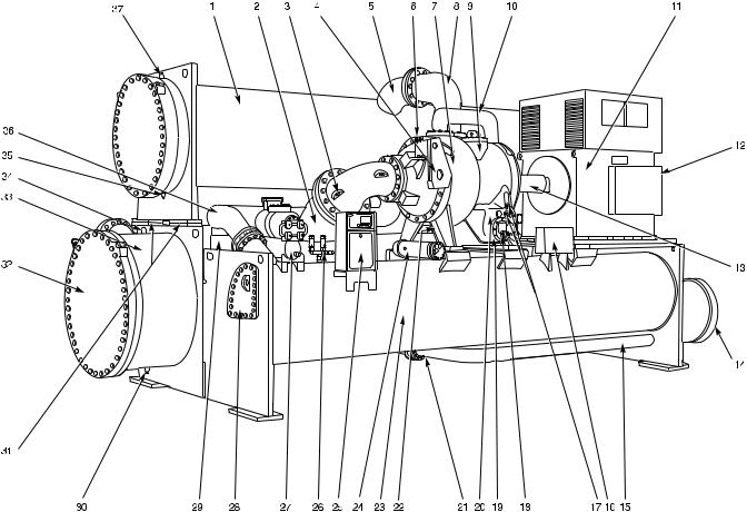
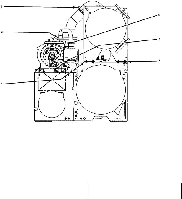
Rigging the Machine Ð The 17/19EX machine can be rigged as an entire assembly. It also has ¯anged connections that allow the compressor, utility vessel, cooler, and condenser sections to be separated for ease of installation. Figures 2 and 3 show 17/19EX components.
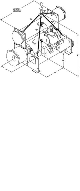
RIG MACHINE ASSEMBLY Ð See rigging instructions on label attached to machine. Also refer to the rigging information found in Fig. 4-9 and Tables 1-12. Lift machine only from the 4 points indicated in rigging guide. Each lifting cable or chain must be capable of supporting the entire weight of the machine.
Lifting machine from points other than those speci®ed may result in serious damage to the unit and personal injury. Rigging equipment and procedures must be adequate for machine weight. See Table 1 for machine weights.
NOTE: These weights are broken down into component sections for use when installing the unit in sections. For the complete machine weight, add all component sections and refrigerant charge together. Total machine weight is also stenciled on the cooler and condenser sections.
2
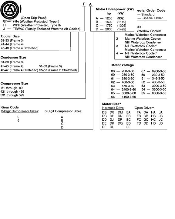
NIH Ð Nozzle-In-Head
*Motors beginning with ``E'' and open drive motors (FA-JD) cannot be used with size 51-89 or 421-469 compressors. ²Open-drive motor codes:
ASME |
UNDERWRITERS' |
ARI (Air Conditioning |
`U' STAMP |
LABORATORIES |
and Refrigeration |
|
|
Institute) |
|
|
PERFORMANCE |
|
|
CERTIFIED |
|
|
(60 Hz Only) |
Fig. 1 Ð Model Number Identi®cation
3

RIG MACHINE COMPONENTS Ð Refer to instructions on page 5, Fig. 6-8, and Carrier certi®ed drawings for machine component disassembly.
IMPORTANT: Only a quali®ed service technician should disassemble and reassemble the machine. After reassembly, the machine must be dehydrated and leak tested.
When rigging components separately, the open drive (17EX) motor must be removed to avoid overturning.
Do not attempt to disconnect ¯anges while the machine is under pressure. Failure to relieve pressure can result in personal injury or damage to the unit.
Before rigging the compressor, disconnect the wires leading from the power panel to the control center at the power panel.
NOTE: Wiring for sensors must be disconnected. Label each wire before removal (see Carrier certi®ed drawings).
Detach all transducer and sensor wires at the sensor, then clip all wire ties necessary to remove the wires from the heat exchangers.
19EX
|
|
|
|
|
LEGEND |
|
|
|
1 |
Ð Refrigerant Liquid Line to Economizer/ |
15 |
Ð |
Motor Sight Glass (Not Shown) |
27 |
Ð |
Oil Cooler |
|
|
|
Storage Vessel |
16 |
Ð |
Oil Filter |
28 |
Ð |
Isolation Valves (Not Shown) |
2 |
Ð |
Cooler Suction Pipe |
17 |
Ð |
Oil Level Sight Glasses (2) |
29 |
Ð |
Refrigerant Filter Drier |
3 |
Ð |
Compressor Suction Elbow |
18 |
Ð |
Cooler Relief Valves (Not Shown) |
30 |
Ð |
Local Interface Display Control Panel |
4 |
Ð |
Condenser |
19 |
Ð |
Oil Heater (Not Shown) |
31 |
Ð |
Economizer/Storage Vessel |
5 |
Ð |
Condenser Discharge Pipe |
20 |
Ð |
Auxiliary Power Panel |
32 |
Ð |
Rigging Guide (Not Shown) |
6 |
Ð |
Compressor Discharge Elbow |
21 |
Ð |
(Field Wiring Terminals) |
33 |
Ð |
Economizer/Storage Vessel |
7 |
Ð |
Guide Vane Actuator |
Pumpdown Unit (Not Shown) |
34 |
Ð |
Relief Valves |
||
8 |
Ð Economizer Gas Line to Compressor |
22 |
Ð |
Low-Side Float Box Cover |
Cooler |
|||
9 |
Ð |
Gear Inspection Cover |
23 |
Ð |
Refrigerant Liquid Line to Cooler |
35 |
Ð |
High-Side Float Box Cover |
10 |
Ð |
2-Stage Hermetic Compressor |
24 |
Ð |
Oil Drain and Charging Valve |
36 |
Ð |
Take-Apart Connections |
11 |
Ð Condenser Waterbox Vent (Not Shown) |
25 |
Ð |
Oil Pump |
37 |
Ð |
Cooler Waterbox Vent |
|
12 |
Ð |
Condenser Marine Waterbox |
26 |
Ð |
Refrigerant Charging/Service |
38 |
Ð |
Cooler Marine Waterbox |
13 |
Ð |
Hermetic Compressor Motor |
|
|
Valve 10 (Not Shown) |
39 |
Ð |
Cooler Waterbox Drain |
14 |
Ð Compressor Motor Terminal Box |
|
|
|
40 |
Ð |
Condenser Waterbox Drain |
|
|
|
(Not Shown) |
|
|
|
|
|
|
Fig. 2 Ð Typical 19EX Installation
4
COMPONENT DISASSEMBLY
To Separate Compressor from the Machine
1.Make sure to check that the machine is at atmospheric pressure before disassembly.
2.Since the center of gravity is high on 17EX machines, the motor MUST be removed before rigging the machine.
3.Suction elbow should be rigged separately (Fig. 6, Item 2). Place slings around the elbow and attach to the hoist. Remove bolting at ¯anges, (Fig. 6, Items 1 and 3). Detach the elbow.
4.Unbolt discharge ¯ange to the condenser at ¯ange (Fig. 8, Item 3). Cut copper lines (Fig. 6, Items 7, 8, and 9).
5. Disconnect and detach the economizer vent line (Fig. 8, Item 4). Unbolt the line at ¯ange (Fig. 8, Item 2).
6.On 19EX machines, disconnect the motor cooling drain line at ¯ange (Fig. 8, Item 5).
7.Disconnect wiring to the control center and power panel.
8.Connect rigging to the compressor.
9.Unbolt compressor from the utility vessel (Fig. 7, Items 2, 4, and 5).
10.Hoist the compressor off of the unit.
11.If the compressor is to be transported or set down, the base should be bolted to sections of 4 in. x 6 in. lumber.
To Separate Condenser from the Machine
1.Unbolt ¯ange (Fig. 6, Item 3).
2.Unbolt ¯ange (Fig. 6, Item 4).
3.Cut copper pipe (Fig. 6, Item 7).
4.Unbolt hot ¯ange (Fig. 7, Item 1).
5.Connect rigging to all corners of the condenser.
6.Unbolt condenser feet (Fig. 8, Items 1 and 6).
|
|
|
|
|
LEGEND |
|
|
|
1 |
Ð |
Condenser |
15 |
Ð |
Refrigerant Liquid Line to Cooler |
27 |
Ð |
Pumpout Unit |
2 |
Ð |
Cooler Suction Pipe |
16 |
Ð |
Power Panel (Field Wiring Terminals) |
28 |
Ð |
High Side Float Box Cover |
3 |
Ð |
Compressor Suction Elbow |
17 |
Ð |
Oil Level Sight Glasses |
29 |
Ð |
Cooler |
4 |
Ð |
Guide Vane Actuator |
18 |
Ð |
Oil Drain and Charging Valve |
30 |
Ð |
Cooler Waterbox Drain |
5 |
Ð |
Condenser Discharge Pipe |
19 |
Ð |
Oil Heater (Hidden) |
31 |
Ð |
Take-Apart Connections (Typical) |
6 |
Ð |
Oil Filter (Hidden) |
20 |
Ð |
Oil Pump |
32 |
Ð |
Cooler Marine Waterbox Cover |
7 |
Ð |
Two-Stage Compressor |
21 |
Ð |
Refrigerant Charging/Service Valve |
33 |
Ð |
Cooler Waterbox |
8 |
Ð |
Compressor Discharge Elbow |
|
|
10 (Not Shown) |
34 |
Ð |
Cooler Waterbox Vent |
9 |
Ð |
Gear Inspection Cover |
22 |
Ð |
Cooler Relief Valves (Not Shown) |
35 |
Ð |
Condenser Waterbox Drain |
10 |
Ð Economizer Gas Line to Compressor |
23 |
Ð |
Economizer/Storage Vessel |
36 |
Ð |
Refrigerant Liquid Line to |
|
11 |
Ð Open Drive Compressor Motor |
24 |
Ð |
Oil Cooler |
|
|
Economizer/Storage Vessel |
|
12 |
Ð Compressor Motor Terminal Box |
25 |
Ð |
Control Center |
37 |
Ð |
Condenser Waterbox Vent |
|
13 |
Ð |
Coupling Guard |
26 |
Ð |
Economizer/Storage Vessel |
|
|
|
14 |
Ð Low-Side Float Box Cover |
|
|
Relief Valves |
|
|
|
|
Fig. 3 Ð Typical 17EX Installation
5
NOTES:
1. Each chain must be capable of supporting the maximum weight of the machine.
2.  = the approximate center of gravity.
3. Maximum possible weight is 88,500 lb (40 166 kg) which includes a maximum of 6,000 lb (2 721 kg) of HFC-134a refrigerant in the storage tank.
17EX FRONT VIEW
|
|
|
|
|
|
|
|
|
|
|
|
|
|
|
|
|
|
LIFTING |
|
|
|
|
|
|
||
|
VESSEL |
MAXIMUM |
|
|
|
|
CHAIN LENGTH |
|
|
|
|
HEIGHT |
|
CENTER OF GRAVITY |
|
|||||||||||
COOLER |
LENGTH |
WEIGHT |
LIFTING |
|
|
|
|
|
|
|
FROM FLOOR |
|
APPROXIMATE LOCATION |
|
||||||||||||
|
|
|
|
|
|
|
|
|
|
|
|
|
|
|||||||||||||
|
|
|
|
|
|
|
|
|
|
|
|
|
|
|
|
``E'' |
|
|
|
|
|
|
|
|||
SIZE |
|
|
|
|
ANGLE |
|
|
|
|
|
|
|
|
|
|
|
|
|
|
|
|
|
|
|
||
|
ft-in. |
mm |
lb |
kg |
|
``A'' |
|
``B'' |
|
``C'' |
``D'' |
|
ft-in. |
|
mm |
``F'' |
``G'' |
``H'' |
||||||||
|
|
|
|
|
|
|
|
|
|
|
|
|
|
|
|
|
|
|
|
|
||||||
|
|
|
|
|
|
ft-in. |
|
mm |
ft-in. |
|
mm |
ft-in. |
mm |
ft-in. |
|
mm |
|
|
|
ft-in. |
mm |
ft-in. |
mm |
ft-in. |
mm |
|
|
|
|
|
|
|
|
|
|
|
|
|
|
|
|
|
|
|
|
|
|
|
|
|
|
|
|
|
|
|
|
|
30° |
10- 3 |
|
3124 |
9-0 |
|
2743 |
16-1 |
|
4902 |
13-6 |
|
4115 |
16-11 |
|
5156 |
|
|
|
|
|
|
45-48 |
|
|
|
|
|
|
|
|
|
|
|
|
|
|
|
|
|
|
|
|
|
|
|
|
|
|
17-0 |
5182 |
88,550 |
40 166 |
45° |
12- 7 |
|
3835 |
11-7 |
|
3531 |
19-1 |
|
5817 |
16-9 |
|
5105 |
20- 8 |
|
6299 |
4-1 |
1245 |
9-1 |
2769 |
4-9 |
1448 |
|
|
|
|
|
|
|
|
|
|
|
|
|
|
|
|
|
|
|
|
|
|
|
|
|
|
|
|
|
|
|
|
|
60° |
17-10 |
|
5436 |
17-1 |
|
5207 |
24-9 |
|
7544 |
22-8 |
|
6909 |
27- 3 |
|
8306 |
|
|
|
|
|
|
|
|
|
|
|
|
|
|
|
|
|
|
|
|
|
|
|
|
|
|
|
|
|
|
|
|
|
Fig. 4 Ð 17EX Machine Rigging Guide
NOTES:
1. Each chain must be capable of supporting the maximum weight of the machine.
2.  = the approximate center of gravity.
3. Maximum possible weight is 78,700 lb (35,698 kg) which includes a maximum of 6,000 lb (2,268 kg) of HFC-134a in the storage tank.
19EX FRONT VIEW
|
|
|
|
|
|
|
|
|
|
|
|
|
|
|
|
|
|
LIFTING |
|
|
|
|
|
|
||
|
VESSEL |
MAXIMUM |
|
|
|
|
|
CHAIN LENGTH |
|
|
|
|
HEIGHT |
|
CENTER OF GRAVITY |
|
||||||||||
COOLER |
LENGTH |
WEIGHT |
LIFTING |
|
|
|
|
|
|
|
|
FROM FLOOR |
|
APPROXIMATE LOCATION |
|
|||||||||||
|
|
|
|
|
|
|
|
|
|
|
|
|
|
|||||||||||||
|
|
|
|
|
|
|
|
|
|
|
|
|
|
|
|
``E'' |
|
|
|
|
|
|
|
|||
SIZE |
|
|
|
|
ANGLE |
|
|
|
|
|
|
|
|
|
|
|
|
|
|
|
|
|
|
|
||
|
ft-in. |
mm |
lb |
kg |
|
``A'' |
|
``B'' |
|
``C'' |
|
``D'' |
|
ft-in. |
|
mm |
``F'' |
``G'' |
``H'' |
|||||||
|
|
|
|
|
|
|
|
|
|
|
|
|
|
|
|
|
|
|
|
|
||||||
|
|
|
|
|
|
ft-in. |
|
mm |
ft-in. |
|
mm |
ft-in. |
mm |
ft-in. |
|
mm |
|
|
|
ft-in. |
mm |
ft-in. |
mm |
ft-in. |
mm |
|
|
|
|
|
|
|
|
|
|
|
|
|
|
|
|
|
|
|
|
|
|
|
|
|
|
|
|
|
|
|
|
|
30° |
7-2 |
|
1880 |
7-2 |
|
1880 |
11-11 |
|
3632 |
11-1 |
|
3378 |
13-7 |
|
4140 |
|
|
|
|
|
|
31-33 |
|
|
|
|
|
|
|
|
|
|
|
|
|
|
|
|
|
|
|
|
|
|
|
|
|
|
12-3 |
3734 |
55,000 |
24 948 |
45° |
8-9 |
|
2667 |
8-9 |
|
2667 |
14- 0 |
|
4267 |
13-4 |
|
4064 |
16-2 |
|
4928 |
3-10 |
1168 |
6-1 |
1854 |
4-6 |
1372 |
|
|
|
|
|
|
|
|
|
|
|
|
|
|
|
|
|
|
|
|
|
|
|
|
|
|
|
|
|
|
|
|
|
60° |
12-5 |
|
3785 |
12-5 |
|
3785 |
18- 0 |
|
5486 |
17-6 |
|
5334 |
20-9 |
|
6325 |
|
|
|
|
|
|
|
|
|
|
|
|
|
|
|
|
|
|
|
|
|
|
|
|
|
|
|
|
|
|
|
|
|
|
|
|
|
|
30° |
6-7 |
|
2007 |
6-9 |
|
2057 |
13- 0 |
|
3962 |
12-2 |
|
3708 |
15-1 |
|
4597 |
|
|
|
|
|
|
41-44 |
|
|
|
|
|
|
|
|
|
|
|
|
|
|
|
|
|
|
|
|
|
|
|
|
|
|
12-3 |
3734 |
70,000 |
31 752 |
45° |
8-0 |
|
2438 |
8-3 |
|
2515 |
14-11 |
|
4547 |
14-3 |
|
4343 |
17-5 |
|
5309 |
4- 0 |
1219 |
6-0 |
1829 |
4-8 |
1422 |
|
|
|
|
|
|
|
|
|
|
|
|
|
|
|
|
|
|
|
|
|
|
|
|
|
|
|
|
|
|
|
|
|
60° |
11-4 |
|
3454 |
11-6 |
|
3505 |
18- 7 |
|
5664 |
18-0 |
|
5486 |
21-7 |
|
6579 |
|
|
|
|
|
|
|
|
|
|
|
|
|
|
|
|
|
|
|
|
|
|
|
|
|
|
|
|
|
|
|
|
|
|
|
|
|
|
30° |
9-1 |
|
2769 |
9-6 |
|
2896 |
15- 1 |
|
4597 |
14-7 |
|
4445 |
16-4 |
|
4978 |
|
|
|
|
|
|
45-48 |
|
|
|
|
|
|
|
|
|
|
|
|
|
|
|
|
|
|
|
|
|
|
|
|
|
|
17-0 |
5182 |
78,700 |
35 698 |
45° |
11-1 |
|
3378 |
11-6 |
|
3505 |
17- 9 |
|
5410 |
17-4 |
|
5283 |
19-8 |
|
5994 |
3-10 |
1168 |
8-3 |
2515 |
4-8 |
1422 |
|
|
|
|
|
|
|
|
|
|
|
|
|
|
|
|
|
|
|
|
|
|
|
|
|
|
|
|
|
|
|
|
|
60° |
15-9 |
|
4800 |
16-0 |
|
4877 |
22-10 |
|
6960 |
22-6 |
|
6858 |
25-5 |
|
7747 |
|
|
|
|
|
|
|
|
|
|
|
|
|
|
|
|
|
|
|
|
|
|
|
|
|
|
|
|
|
|
|
|
|
Fig. 5 Ð 19EX Machine Rigging Guide
6
NOTE: Item numbers are referenced in Rigging the Machine, Component Disassembly section.
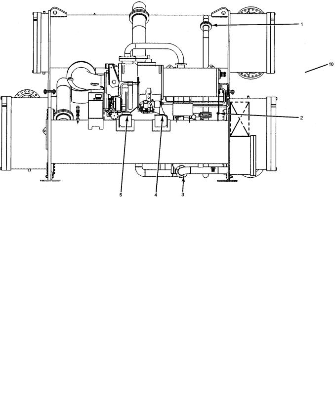
Fig. 6 Ð Typical Top View (19EX Shown)
NOTE: Item numbers are referenced in Rigging the Machine, Component Disassembly section.
Fig. 7 Ð Typical Side View (19EX Shown)
7
NOTE: Item numbers are referenced in Rigging the Machine, Component Disassembly section.
Fig. 8 Ð Typical Motor End View (19EX Shown)
To Separate Cooler From Utility Vessel
1.Remove condenser (see previous section).
2.Cut copper lines (Fig. 6, Items 6 and 8).
3.Unbolt liquid refrigerant line at ¯ange (Fig. 7, Item 3).
4.Connect rigging to all four corners of the cooler before lifting the unit.
5.Unbolt connections to the utility vessel (Fig. 6, Items 5 and 10).
To Assemble the Machine
1.Follow disassembly instructions (in reverse order) and bolt all ¯anges back together using a gasket sealant. The following torque requirements are speci®ed:
2.All gasketed or O-ring joints which have been disassembled must be assembled using new gaskets and O-rings. These new gaskets and O-rings (along with gasket sealant, O-ring lubricant, and copper line couplings) are available through your Carrier representative.
3.Braze all copper lines back together using a suitable brazing material for copper. Carrier recommends an AWS (American Welding Society) Classi®cation BCuP-2.
Do not tilt the compressor; oil is contained in the oil sump.
FIG. |
ITEM NO. |
|
TORQUE |
|
ft-lb |
|
N-m |
||
|
|
|
||
|
3 |
580 |
|
786 |
6 |
1 or 4 |
170 |
|
230 |
|
5 and 10 |
840* |
|
1139* |
7 |
1 |
380 |
|
515 |
4 and 5 |
250 |
|
340 |
|
|
|
|||
|
1 and 6 |
280 |
|
380 |
8 |
2 |
170 |
|
230 |
3 |
380 |
|
515 |
|
|
|
|||
|
5 |
71 |
|
96 |
|
|
|
|
|
N-m Ð Newton Meters
Additional Notes
1.Use silicon grease on new O-rings when re®tting.
2.Use gasket sealant on new gaskets when re®tting.
3.Cooler, utility, and condenser vessels may be rigged vertically, as separate components. Rigging should be ®xed to all four corners of the tube sheet.
4.New gaskets, grease for O-rings, and gasket sealant for a complete take-apart operation are available in a kit. Contact your Carrier representative.
*This torque is used to rig the entire machine. Once the machine is in place, if no further rigging is anticipated, the bolt torque can be reduced to 280 ft-lb (380 N-m).
8
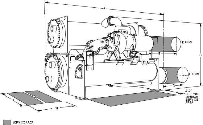
NOTES:
1.Certi®ed drawings available upon request.
2.Service access should be provided per American Society of Heating, Refrigeration, and Air Conditioning Engineers (ASHRAE) 15, latest edition, National Fire Protection Association (NFPA) 70, and local safety codes.
DIMENSIONS
CONDENSER |
|
|
A (LENGTH)² |
|
|
|
|
B (WIDTH) |
|
|
|
C (HEIGHT) |
|
|
H (TUBE PULL) |
|||||||||||||||
|
|
|
|
|
|
|
|
17EX** |
|
19EX |
|
|
|
|
|
|
|
|
|
|
|
|
|
|
||||||
SIZE |
|
ft-in. |
|
mm |
|
|
|
|
|
|
ft-in. |
|
|
mm |
|
|
ft-in. |
|
|
mm |
||||||||||
|
|
|
ft-in. |
|
mm |
ft-in. |
|
|
mm |
|
|
|
|
|
|
|
||||||||||||||
|
|
|
|
|
|
|
|
|
|
|
|
|
|
|
|
|
|
|
|
|
|
|
||||||||
31 - 33 |
15-6 |
|
4724 |
|
|
N/A |
|
N/A |
8-10 |
|
|
2692 |
10-81¤2 |
|
|
3264 |
|
12-10 |
|
3912 |
||||||||||
41 - 43 |
15-6 |
|
4724 |
|
|
N/A |
|
N/A |
|
|
|
|
|
|
12-2 |
|
|
3708 |
|
12-10 |
|
3912 |
||||||||
45 - 47 |
20-3 |
|
6172 |
|
|
12-2 |
|
3708 |
|
9-41¤2 |
|
|
2858 |
|
|
|
17- 6 |
|
5334 |
|||||||||||
|
|
|
|
|
|
|
|
|
|
|
|
|
|
|
||||||||||||||||
51 - 53 |
15-6 |
|
4724 |
|
|
N/A |
|
N/A |
|
|
12-5 |
|
|
3785 |
|
12-10 |
|
3912 |
||||||||||||
|
|
|
|
|
|
|
|
|
|
|
|
|
|
|||||||||||||||||
55 - 57 |
20-3 |
|
6172 |
|
|
12-2 |
|
3708 |
|
|
|
|
|
|
|
|
|
|
17- 6 |
|
5334 |
|||||||||
|
|
|
|
|
|
|
|
|
|
|
|
|
|
|
|
|
|
|
||||||||||||
|
|
|
|
|
|
|
|
|
|
|
|
|
|
|
|
|
|
|
|
|
|
|
|
|
|
|
|
|
|
|
|
|
|
|
|
|
|
|
|
|
SERVICE CLEARANCES |
|
|
|
|
|
|
|
|
|
|
|
|
||||||||
|
|
|
|
|
|
|
|
|
|
|
|
|
|
|
|
|
|
|
|
|
|
|
||||||||
COMPONENT |
|
|
|
D (DIAMETER)²² |
|
E (LENGTH)²² |
|
|
F (DIAMETER) |
|
|
G (LENGTH) |
||||||||||||||||||
|
|
|
ft-in. |
|
|
mm |
|
ft-in. |
|
mm |
|
|
ft-in. |
|
|
mm |
|
|
ft-in. |
|
|
mm |
||||||||
|
|
|
|
|
|
|
|
|
|
|
|
|
|
|
||||||||||||||||
Motor DB - DQ |
|
|
|
1-111¤4 |
|
|
591 |
|
|
3- 71¤2 |
|
1105 |
|
|
Ð |
|
|
Ð |
|
|
Ð |
|
Ð |
|||||||
Motor EA - ED |
|
|
|
2- 23¤4 |
|
|
679 |
|
|
3-101¤4 |
|
1175 |
|
|
Ð |
|
|
Ð |
|
|
Ð |
|
Ð |
|||||||
Motor EE |
|
|
|
|
|
|
|
4- 11¤4 |
|
1251 |
|
|
Ð |
|
|
Ð |
|
|
|
Ð |
|
|
Ð |
|||||||
|
|
|
|
|
|
|
|
|
|
|
|
|
|
|
|
|
|
|||||||||||||
Low-Side Float |
|
|
|
Ð |
|
|
Ð |
|
|
Ð |
|
|
Ð |
|
|
|
2-6 |
1¤2 |
|
775 |
|
|
1-0 |
|
305 |
|||||
|
|
|
|
|
|
|
|
|
|
|
NOZZLE SIZES |
|
|
|
|
|
|
|
|
|
|
|
|
|
|
|||||
|
|
|
|
|
|
|
|
|
|
|
|
|
|
|
|
|
|
|
|
|
|
|
|
|
|
|||||
HEAT |
|
|
|
|
|
|
|
|
|
|
|
|
|
|
|
|
NOZZLE SIZES (in.)| |
|
|
|
|
|
|
|||||||
|
|
|
NOZZLE TYPE |
|
|
|
Cooler Passes |
|
|
|
|
|
|
Condenser Passes |
||||||||||||||||
EXCHANGER |
|
|
|
|
|
|
|
|
|
|
|
|
||||||||||||||||||
|
|
|
|
|
|
|
|
|
|
1 |
|
2 |
|
|
3 |
|
|
1 |
|
|
2 |
3 |
||||||||
31 - 33 |
|
|
|
|
Marine |
|
|
12 |
|
10 |
|
|
10 |
|
|
12 |
|
10 |
10 |
|||||||||||
|
|
|
|
NIH |
|
|
12 |
|
10 |
|
|
10 |
|
|
Ð |
|
|
10 |
10 |
|||||||||||
|
|
|
|
|
|
|
|
|
|
|
|
|
|
|||||||||||||||||
41 - 48 |
|
|
|
|
Marine |
|
|
20 |
|
14 |
|
|
12 |
|
|
20 |
|
14 |
12 |
|||||||||||
|
|
|
|
NIH |
|
|
18 |
|
14 |
|
|
10 |
|
|
18 |
|
12 |
10 |
||||||||||||
|
|
|
|
|
|
|
|
|
|
|
|
|
||||||||||||||||||
51 - 57 |
|
|
|
|
Marine |
|
|
Ð |
|
Ð |
|
|
Ð |
|
|
Ð |
|
|
|
|
16 |
Ð |
||||||||
|
|
|
|
NIH |
|
|
Ð |
|
Ð |
|
|
Ð |
|
|
20 |
|
|
|
|
16 |
Ð |
|||||||||
|
|
|
|
|
|
|
|
|
|
|
|
|
|
|
|
|||||||||||||||
LEGEND
NIH Ð Nozzle-In-Head
*Distance required for tube removal may be either end.
²Based on 2-pass, nozzle-in-head (NIH) waterboxes with 150 psi (1038 kPa) covers.
**Overall width of units with 17 Series compressors will vary greatly depending upon the application. See the appropriate certi®ed drawings.
²²For hermetic motors (19 Series) only.
\The table at right provides additional information on nozzle sizes. Victaulic grooves are standard for these nozzles. Optional 150 psi (1034 kPa) and 300 psi (2068 kPa) ¯anges are available.
¶In conformance with ASA B36.10 (American Standards Association).
NOMINAL PIPE SIZE (in.) |
SCHEDULE¶ |
WALL THICKNESS |
||
in. |
mm |
|||
|
|
|||
10 |
40 |
.365 |
9.27 |
|
12 |
Std |
.375 |
9.53 |
|
14 |
30 |
.375 |
9.53 |
|
16 |
30 |
.375 |
9.53 |
|
18 |
Std |
.375 |
9.53 |
|
20 |
20 |
.375 |
9.53 |
|
|
|
|
|
|
Fig. 9 Ð Typical Dimensions
9
Table 1 Ð 17/19EX Heat Exchanger, Economizer/Storage Vessel, Piping, and Pumpout Unit Weights*
|
|
COOLER |
|
|
|
|
|
|
|
COOLER |
|
|
|
|
|
ECONOMIZER/ |
ECONOMIZER |
MISCELLANEOUS |
PUMPOUT |
|||||||||||||||||||||
|
|
TOTAL |
|
|
|
|
|
|
|
|
|
|
|
|
|
STORAGE |
||||||||||||||||||||||||
COOLER |
|
|
|
|
|
|
|
|
CHARGE |
|
|
|
|
|
|
REFRIGERANT |
|
|
PIPING |
|
UNIT |
|||||||||||||||||||
|
WEIGHT |
|
|
|
|
|
|
|
|
|
|
|
|
|
VESSEL** |
|
|
|
|
|||||||||||||||||||||
SIZE² |
|
|
|
|
|
|
|
|
|
|
|
|
|
|
|
|
|
|
|
|
|
|
|
|
|
|
|
|
|
|
|
|
|
|
|
|
|
|
|
|
Dry |
|
Operating²² |
|
Refrigerant |
|
|
|
Water |
|
|
|
|
lb |
|
|
kg |
|
lb |
|
|
kg |
|
|
lb |
|
|
kg |
lb |
kg |
|||||||||||
|
|
|
|
|
|
|
|
|
|
|
|
|
|
|
|
|
|
|
||||||||||||||||||||||
|
lb |
kg |
|
lb |
|
kg |
|
lb |
|
kg |
lb |
|
gal |
|
kg |
|
L |
|
|
|
|
|
|
|
|
|
|
|
||||||||||||
|
|
|
|
|
|
|
|
|
|
|
|
|
|
|
|
|
|
|
|
|
|
|
|
|
|
|
|
|
||||||||||||
31 |
14,173 |
6 429 |
|
17,518 |
7 946 |
|
1,540 |
|
699 |
1,810 |
|
217 |
|
821 |
821 |
|
|
|
|
|
|
|
|
|
|
|
|
|
|
|
|
|
|
|
|
|
||||
32 |
14,538 |
6 594 |
|
18,117 |
8 218 |
|
1,640 |
|
744 |
1,944 |
|
233 |
|
882 |
882 |
|
7,169 |
|
3252 |
|
610 |
|
277 |
|
820 |
|
|
372 |
|
|
||||||||||
33 |
14,904 |
6 760 |
|
18,722 |
8 492 |
|
1,740 |
|
789 |
2,078 |
|
249 |
|
943 |
943 |
|
|
|
|
|
|
|
|
|
|
|
|
|
|
|
|
|
|
|
|
|
||||
41 |
21,674 |
9 831 |
|
26,120 |
11 848 |
|
1,900 |
|
862 |
2,441 |
|
293 |
|
1 107 |
1 107 |
|
|
|
|
|
|
|
|
|
|
|
|
|
|
|
|
|
|
|
|
|
||||
42 |
22,019 |
9 988 |
|
26,736 |
12 127 |
|
2,000 |
|
907 |
2,575 |
|
309 |
|
1 168 |
1 168 |
|
7,169 |
|
3 252 |
|
610 |
|
277 |
|
1,095 |
|
|
497 |
|
|
||||||||||
43 |
22,364 |
10 144 |
|
27,322 |
12 393 |
|
2,100 |
|
953 |
2,709 |
|
325 |
|
1 229 |
1 229 |
|
|
|
|
|
|
|
210 |
95 |
||||||||||||||||
|
|
|
|
|
|
|
|
|
|
|
|
|
|
|
|
|
|
|
|
|
|
|
|
|||||||||||||||||
44 |
23,841 |
10 814 |
|
29,836 |
13 533 |
|
2,190 |
|
993 |
3,285 |
|
394 |
|
1 490 |
1 490 |
|
|
|
|
|
|
|
|
|
|
|
|
|
|
|
|
|
|
|
|
|
||||
45 |
25,032 |
11 354 |
|
30,790 |
13 966 |
|
2,260 |
|
1 025 |
3,006 |
|
361 |
|
1 363 |
1 363 |
|
|
|
|
|
|
|
|
|
|
|
|
|
|
|
|
|
|
|
|
|
||||
46 |
25,529 |
11 580 |
|
31,658 |
14 360 |
|
2,360 |
|
1 070 |
3,192 |
|
383 |
|
1 448 |
1 448 |
|
7,900 |
|
3 583 |
|
840 |
|
381 |
|
1,149 |
|
|
521 |
|
|
||||||||||
47 |
26,025 |
11 805 |
|
32,496 |
14 740 |
|
2,460 |
|
1 116 |
3,378 |
|
405 |
|
1 532 |
1 532 |
|
|
|
|
|
|
|
|
|
||||||||||||||||
|
|
|
|
|
|
|
|
|
|
|
|
|
|
|
|
|
|
|
|
|
|
|
|
|
|
|||||||||||||||
48 |
28,153 |
12 770 |
|
36,053 |
16 353 |
|
2,540 |
|
1 152 |
4,173 |
|
500 |
|
1 893 |
1 893 |
|
|
|
|
|
|
|
|
|
|
|
|
|
|
|
|
|
|
|
|
|
||||
|
|
|
|
|
|
|
|
|
|
|
|
|
|
|
|
|
|
|
|
|
|
|
|
|
|
|
|
|
|
|
|
|
|
|||||||
|
|
|
|
|
|
|
|
|
|
|
|
|
|
|
|
|
|
|
|
|
|
|
|
|
|
|
||||||||||||||
|
|
CONDENSER |
|
CONDENSER TOTAL WEIGHT |
|
|
|
|
|
|
CONDENSER CHARGE |
|
|
|
|
|
|
|
||||||||||||||||||||||
|
|
|
|
|
Dry |
|
|
Operating²² |
|
Refrigerant |
|
|
|
|
|
|
|
Water |
|
|
|
|
|
|
|
|||||||||||||||
|
|
SIZE² |
|
|
|
|
|
|
|
|
|
|
|
|
|
|
|
|
|
|
|
|
||||||||||||||||||
|
|
|
|
|
|
lb |
|
|
|
kg |
lb |
|
|
|
kg |
|
lb |
|
kg |
|
|
lb |
|
|
gal |
|
kg |
|
L |
|
|
|
||||||||
|
|
|
31 |
|
10,454 |
|
|
4 742 |
13,022 |
|
|
5 907 |
|
950 |
|
431 |
|
|
1,613 |
|
193 |
|
732 |
|
732 |
|
|
|
|
|||||||||||
|
|
|
32 |
|
10,809 |
|
|
4 903 |
13,514 |
|
|
6 130 |
|
950 |
|
431 |
|
|
1,750 |
|
210 |
|
794 |
|
794 |
|
|
|
|
|||||||||||
|
|
|
33 |
|
11,164 |
|
|
5 064 |
14,000 |
|
|
6 350 |
|
950 |
|
431 |
|
|
1,886 |
|
226 |
|
855 |
|
855 |
|
|
|
|
|||||||||||
|
|
|
41 |
|
13,768 |
|
|
6 245 |
16,999 |
|
|
7 711 |
|
1,090 |
|
494 |
|
|
2,146 |
|
257 |
|
973 |
|
973 |
|
|
|
|
|||||||||||
|
|
|
42 |
|
14,118 |
|
|
6 404 |
17,498 |
|
|
7 937 |
|
1,090 |
|
494 |
|
|
2,282 |
|
274 |
|
1 035 |
|
1 035 |
|
|
|
|
|||||||||||
|
|
|
43 |
|
14,468 |
|
|
6 563 |
17,978 |
|
|
8 155 |
|
1,090 |
|
494 |
|
|
2,419 |
|
290 |
|
1 097 |
|
1 097 |
|
|
|
|
|||||||||||
|
|
|
45 |
|
16,676 |
|
|
7 564 |
20,800 |
|
|
9 435 |
|
1,400 |
|
635 |
|
|
2,720 |
|
326 |
|
1 234 |
|
1 234 |
|
|
|
|
|||||||||||
|
|
|
46 |
|
17,172 |
|
|
7 789 |
21,489 |
|
|
9 747 |
|
1,400 |
|
635 |
|
|
2,908 |
|
348 |
|
1 319 |
|
1 319 |
|
|
|
|
|||||||||||
|
|
|
47 |
|
17,669 |
|
|
8 015 |
22,178 |
|
|
10 060 |
|
1,400 |
|
635 |
|
|
3,096 |
|
371 |
|
1 404 |
|
1 404 |
|
|
|
|
|||||||||||
|
|
|
51 |
|
17,188 |
|
|
7 796 |
20,993 |
|
|
9 522 |
|
1,100 |
|
499 |
|
|
2,707 |
|
325 |
|
1 228 |
|
1 228 |
|
|
|
|
|||||||||||
|
|
|
52 |
|
17,848 |
|
|
8 096 |
21,923 |
|
|
9 944 |
|
1,100 |
|
499 |
|
|
2,964 |
|
355 |
|
1 344 |
|
1 344 |
|
|
|
|
|||||||||||
|
|
|
53 |
|
18,400 |
|
|
8 346 |
22,682 |
|
|
10 288 |
|
1,100 |
|
499 |
|
|
3,178 |
|
381 |
|
1 442 |
|
1 442 |
|
|
|
|
|||||||||||
|
|
|
55 |
|
20,725 |
|
|
9 401 |
25,598 |
|
|
11 611 |
|
1,420 |
|
644 |
|
|
3,453 |
|
412 |
|
1 566 |
|
1 566 |
|
|
|
|
|||||||||||
|
|
|
56 |
|
21,663 |
|
|
9 826 |
26,896 |
|
|
12 199 |
|
1,420 |
|
644 |
|
|
3,808 |
|
457 |
|
1 727 |
|
1 727 |
|
|
|
|
|||||||||||
|
|
|
57 |
|
22,446 |
|
10 181 |
27,980 |
|
|
12 691 |
|
1,420 |
|
644 |
|
|
4,105 |
|
492 |
|
1 862 |
|
1 862 |
|
|
|
|
||||||||||||
|
|
|
|
|
|
|
|
|
|
|
|
|
|
|
|
|
|
|
|
|
|
|
|
|
|
|
|
|
|
|
|
|
|
|
|
|
|
|
|
|
*If a machine con®guration other than 2-pass, 150 psig (1034 kPa), NIH waterbox con®guration is used, refer to Tables 3 and 4 to obtain the additional dry and water weights that must be added to the values shown in this table.
²Cooler and condenser weights shown are based upon 2-pass, nozzle-in-head (NIH) waterboxes with 150 psig (1034 kPa) covers. Includes components attached to cooler, but does not include suction/discharge, elbow, or other interconnecting piping.
**Dry weight includes all components attached to economizer: Covers, ¯oat valves, brackets, control center (31 lb [14 kg]), and power panel (20 lb [9 kg]). Dry weight does not include compressor weight, motor weight, or pumpout condensing unit weight. The pumpout condensing unit weight is 210 lb (95 kg). For compressor and motor weights, refer to Tables 6, 7, 8, 10A, and 10B.
²²Operating weight includes the sum of the dry weight, refrigerant weight, and water weight.
Table 2 Ð Refrigerant Charge
HEAT EXCHANGER SIZE |
COOLER CHARGE |
CONDENSER CHARGE |
ECONOMIZER CHARGE |
TOTAL REFRIGERANT |
||||||
|
CHARGE* |
|||||||||
|
|
|
|
|
|
|
|
|
||
Cooler |
Condenser |
lb |
kg |
lb |
kg |
lb |
kg |
lb |
|
kg |
31 |
31 |
1540 |
699 |
950 |
431 |
|
|
3100 |
|
1 406 |
32 |
32 |
1640 |
744 |
950 |
431 |
|
|
3200 |
|
1 452 |
33 |
33 |
1740 |
789 |
950 |
431 |
|
|
3300 |
|
1 497 |
41 |
41 |
1900 |
862 |
1090 |
494 |
|
|
3600 |
|
1 633 |
42 |
42 |
2000 |
907 |
1090 |
494 |
610 |
277 |
3700 |
|
1 678 |
43 |
43 |
2100 |
953 |
1090 |
494 |
|
|
3800 |
|
1 724 |
44 |
51 |
2190 |
993 |
1100 |
499 |
|
|
3900 |
|
1 769 |
44 |
52 |
2190 |
993 |
1100 |
499 |
|
|
3900 |
|
1 769 |
44 |
53 |
2190 |
993 |
1100 |
499 |
|
|
3900 |
|
1 769 |
45 |
45 |
2260 |
1 025 |
1400 |
635 |
|
|
4500 |
|
2 041 |
46 |
46 |
2360 |
1 070 |
1400 |
635 |
|
|
4600 |
|
2 087 |
47 |
47 |
2460 |
1 116 |
1400 |
635 |
844 |
381 |
4700 |
|
2 132 |
48 |
55 |
2540 |
1 152 |
1420 |
644 |
4800 |
|
2 177 |
||
|
|
|
||||||||
48 |
56 |
2540 |
1 152 |
1420 |
644 |
|
|
4800 |
|
2 177 |
48 |
57 |
2540 |
1 152 |
1420 |
644 |
|
|
4800 |
|
2 177 |
|
|
|
|
|
|
|
|
|
|
|
*Total machine refrigerant charge includes the cooler, condenser, and economizer.
NOTE: Regulations mandate that machine shipping charge is limited to 7500 lb (3402 kg).
10
 Loading...