


17EX Externally Geared Centrifugal Liquid Chillers 50/60 Hz 1500 to 2250 Nominal Tons (5280 to 7910 kW)
Start-Up, Operation, and Maintenance Instructions
SAFETY CONSIDERATIONS
Centrifugal liquid chillers are designed to provide safe and reliable service when operated within design speci- ®cations. When operating this equipment, use good judgment and safety precautions to avoid damage to equipment and property or injury to personnel.
Be sure you understand and follow the procedures and safety precautions contained in the chiller instructions as well as those listed in this guide.
DO NOT VENT refrigerant relief valves within a building. Outlet from rupture disc or relief valve must be vented outdoors in accordance with the latest edition of ASHRAE (American Society of Heating, Refrigeration, and Air Conditioning Engineers) 15. The accumulation of refrigerant in an enclosed space can displace oxygen and cause asphyxiation.
PROVIDE adequate ventilation in accordance with ASHRAE 15, especially for enclosed and low overhead spaces. Inhalation of high concentrations of vapor is harmful and may cause heart irregularities, unconsciousness, or death. Misuse can be fatal. Vapor is heavier than air and reduces the amount of oxygen available for breathing. Product causes eye and skin irritation. Decomposition products are hazardous.
DO NOT USE OXYGEN to purge lines or to pressurize a chiller for any purpose. Oxygen gas reacts violently with oil, grease, and other common substances.
NEVER EXCEED speci®ed test pressures, VERIFY the allowable test pressure by checking the instruction literature and the design pressures on the equipment nameplate.
DO NOT USE air for leak testing. Use only refrigerant or dry nitrogen.
DO NOT VALVE OFF any safety device.
BE SURE that all pressure relief devices are properly installed and functioning before operating any machine.
DO NOT WELD OR FLAME CUT any refrigerant line or vessel until all refrigerant (liquid and vapor) has been removed from chiller. Traces of vapor should be displaced with dry air or nitrogen and the work area should be well ventilated. Refrigerant in contact with an open ¯ame produces toxic gases.
DO NOT USE eyebolts or eyebolt holes to rig chiller sections or the entire assembly.
DO NOT work on high-voltage equipment unless you are a quali- ®ed electrician.
DO NOT WORK ON electrical components, including control panels, switches, starters, or oil heater until you are sure ALL POWER IS OFF and no residual voltage can leak from capacitors or solidstate components.
LOCK OPEN AND TAG electrical circuits during servicing. IF WORK IS INTERRUPTED, con®rm that all circuits are deenergized before resuming work.
AVOID SPILLING liquid refrigerant on skin or getting it into the eyes. USE SAFETY GOGGLES. Wash any spills from the skin with soap and water. If any enters the eyes, IMMEDIATELY FLUSH EYES with water and consult a physician.
NEVER APPLY an open ¯ame or live steam to a refrigerant cylinder. Dangerous overpressure can result. When necessary to heat refrigerant, use only warm (110 F [43 C]) water.
DO NOT REUSE disposable (nonreturnable) cylinders or attempt to re®ll them. It is DANGEROUS AND ILLEGAL. When cylinder is emptied, evacuate remaining gas pressure, loosen the collar and unscrew and discard the valve stem. DO NOT INCINERATE.
CHECK THE REFRIGERANT TYPE before adding refrigerant to the chiller. The introduction of the wrong refrigerant can cause damage or malfunction to this chiller.
Operation of this equipment with refrigerants other than those cited herein should comply with ASHRAE-15 (latest edition). Contact Carrier for further information on use of this chiller with other refrigerants.
DO NOT ATTEMPT TO REMOVE ®ttings, covers, etc., while chiller is under pressure or while chiller is running. Be sure pressure is at 0 psig (0 kPa) before breaking any refrigerant connection.
CAREFULLY INSPECT all relief devices, rupture discs, and other relief devices AT LEAST ONCE A YEAR. If chiller operates in a corrosive atmosphere, inspect the devices at more frequent intervals.
DO NOT ATTEMPT TO REPAIR OR RECONDITION any relief device when corrosion or build-up of foreign material (rust, dirt, scale, etc.) is found within the valve body or mechanism. Replace the device.
DO NOT install relief devices in series or backwards.
USE CARE when working near or in line with a compressed spring. Sudden release of the spring can cause it and objects in its path to act as projectiles.
RUN WATER PUMPS when removing, transferring, or charging refrigerant.
DO NOT STEP on refrigerant lines. Broken lines can whip about and cause personal injury.
DO NOT climb over a chiller. Use platform, catwalk, or staging. Follow safe practices when using ladders.
USE MECHANICAL EQUIPMENT (crane, hoist, etc.) to lift or move inspection covers or other heavy components. Even if components are light, use such equipment when there is a risk of slipping or losing your balance.
BE AWARE that certain automatic start arrangements CAN ENGAGE THE STARTER. Open the disconnect ahead of the starter in addition to shutting off the machine or pump.
USE only repair or replacement parts that meet the code requirements of the original equipment.
DO NOT VENT OR DRAIN waterboxes containing industrial brines, liquid, gases, or semisolids without permission of your process control group.
DO NOT LOOSEN waterbox cover bolts until the waterbox has been completely drained.
DOUBLE-CHECK that coupling nut wrenches, dial indicators, or other items have been removed before rotating any shafts.
DO NOT LOOSEN a packing gland nut before checking that the nut has a positive thread engagement.
PERIODICALLY INSPECT all valves, ®ttings, and piping for corrosion, rust, leaks, or damage.
PROVIDE A DRAIN connection in the vent line near each pressure relief device to prevent a build-up of condensate or rain water.
Manufacturer reserves the right to discontinue, or change at any time, speci®cations or designs without notice and without incurring obligations.
Book |
2 |
|
PC 211 |
Catalog No. 531-721 |
Printed in U.S.A. |
Form 17EX-1SS |
Pg 1 |
7-97 |
Replaces: New |
Tab |
5d |
|
|
|
|
|
|
|
|
|
|
|
|
|
|
|
|
|
|
CONTENTS
Page Page
SAFETY CONSIDERATIONS . . . . . . . . . . . . . . . . . . . . . . 1
INTRODUCTION . . . . . . . . . . . . . . . . . . . . . . . . . . . . . . . . 5
ABBREVIATIONS . . . . . . . . . . . . . . . . . . . . . . . . . . . . . . . 5
17EX CHILLER FAMILIARIZATION . . . . . . . . . . . . . . . . . 5
Chiller Identi®cation Label . . . . . . . . . . . . . . . . . . . . . . . 5
System Components . . . . . . . . . . . . . . . . . . . . . . . . . . . . 5
Cooler . . . . . . . . . . . . . . . . . . . . . . . . . . . . . . . . . . . . . . . . 5
Condenser . . . . . . . . . . . . . . . . . . . . . . . . . . . . . . . . . . . . 5
Compressor . . . . . . . . . . . . . . . . . . . . . . . . . . . . . . . . . . . 5
Control Center . . . . . . . . . . . . . . . . . . . . . . . . . . . . . . . . . 5
Motor Starter (Purchased Separately) . . . . . . . . . . . . . . 5
Economizer/Storage Vessel . . . . . . . . . . . . . . . . . . . . . . 5
REFRIGERATION CYCLE . . . . . . . . . . . . . . . . . . . . . . . 5-8
OIL COOLING CYCLE . . . . . . . . . . . . . . . . . . . . . . . . . . . 8
Compressor Oil Cooling . . . . . . . . . . . . . . . . . . . . . . . . . 8
External Gear Oil Cooling . . . . . . . . . . . . . . . . . . . . . . . . 8
LUBRICATION CYCLE . . . . . . . . . . . . . . . . . . . . . . . . . . 8,9
Compressor Lubrication Cycle . . . . . . . . . . . . . . . . . . . 8
External Gear Lubrication Cycle . . . . . . . . . . . . . . . . . . 9
STARTERS . . . . . . . . . . . . . . . . . . . . . . . . . . . . . . . . . . . . 9
CONTROLS . . . . . . . . . . . . . . . . . . . . . . . . . . . . . . . . . 11-43 De®nitions . . . . . . . . . . . . . . . . . . . . . . . . . . . . . . . . . . . . 11
·ANALOG SIGNAL
·DIGITAL SIGNAL
·VOLATILE MEMORY
General . . . . . . . . . . . . . . . . . . . . . . . . . . . . . . . . . . . . . . 11
PIC System Components . . . . . . . . . . . . . . . . . . . . . . . 12
·PROCESSOR/SENSOR INPUT/OUTPUT MODULE (PSIO)
·STARTER MANAGEMENT MODULE (SMM)
·LOCAL INTERFACE DEVICE (LID)
·SIX-PACK RELAY BOARD
·EIGHT-INPUT MODULES
·FOUR-IN/TWO-OUT (4-IN/2-OUT) MODULE
·OIL HEATER CONTACTOR (1C)
·COMPRESSOR OIL PUMP CONTACTOR (2C) AND GEAR OIL PUMP CONTACTOR (5C)
·HOT GAS BYPASS CONTACTOR RELAY (3C) (Optional)
·OIL AUXILIARY RELAY (4C)
·CONTROL TRANSFORMERS (T1-T4)
·CONTROL AND OIL HEATER VOLTAGE SELECTOR (S1)
·OIL DIFFERENTIAL PRESSURE/POWER SUPPLY
MODULE
LID Operation and Menus . . . . . . . . . . . . . . . . . . . . . . . 16
·GENERAL
·ALARMS AND ALERTS
·LID DEFAULT SCREEN MENU ITEMS
·MENU STRUCTURE
·TO VIEW OR CHANGE POINT STATUS
·OVERRIDE OPERATIONS
·TO VIEW OR CHANGE TIME SCHEDULE OPERATION
·TO VIEW AND CHANGE SET POINTS
·SERVICE OPERATION
PIC System Functions . . . . . . . . . . . . . . . . . . . . . . . . . . 32
·CAPACITY CONTROL
·ENTERING CHILLED WATER CONTROL
·DEADBAND
·PROPORTIONAL BANDS AND GAIN
·DEMAND LIMITING
·CHILLER TIMERS
·OCCUPANCY SCHEDULE
Safety Controls . . . . . . . . . . . . . . . . . . . . . . . . . . . . . . . 33
· SHUNT TRIP
Default Screen Freeze . . . . . . . . . . . . . . . . . . . . . . . . . 33
Auxiliary Compressor Oil Pump Control . . . . . . . . . . 33
Auxiliary Gear Oil Pump Control . . . . . . . . . . . . . . . . 33
Shaft Seal Oil Control . . . . . . . . . . . . . . . . . . . . . . . . . . 33
Ramp Loading Control . . . . . . . . . . . . . . . . . . . . . . . . . 33
Capacity Override . . . . . . . . . . . . . . . . . . . . . . . . . . . . . 35
High Discharge Temperature Control . . . . . . . . . . . . . 35
Oil Sump Temperature Control . . . . . . . . . . . . . . . . . . 35
Oil Cooler . . . . . . . . . . . . . . . . . . . . . . . . . . . . . . . . . . . . 36
Remote Start/Stop Controls . . . . . . . . . . . . . . . . . . . . . 36
Spare Safety Inputs . . . . . . . . . . . . . . . . . . . . . . . . . . . 36
Spare Alarm Contacts . . . . . . . . . . . . . . . . . . . . . . . . . 36
Condenser Pump Control . . . . . . . . . . . . . . . . . . . . . . 36
Condenser Freeze Prevention . . . . . . . . . . . . . . . . . . . 36
Tower-Fan Relay . . . . . . . . . . . . . . . . . . . . . . . . . . . . . . 36
Auto. Restart After Power Failure . . . . . . . . . . . . . . . . 36
Water/Brine Reset . . . . . . . . . . . . . . . . . . . . . . . . . . . . . 37
Demand Limit Control, Option (Requires Optional
8-Input Module) . . . . . . . . . . . . . . . . . . . . . . . . . . . . . 37
Surge Prevention Algorithm . . . . . . . . . . . . . . . . . . . . 37
Surge Protection . . . . . . . . . . . . . . . . . . . . . . . . . . . . . . 38
Lead/Lag Control . . . . . . . . . . . . . . . . . . . . . . . . . . . . . 38
·COMMON POINT SENSOR INSTALLATION
·CHILLER COMMUNICATION WIRING
·LEAD/LAG OPERATION
·FAULTED CHILLER OPERATION
·LOAD BALANCING
·AUTO. RESTART AFTER POWER FAILURE
Ice Build Control . . . . . . . . . . . . . . . . . . . . . . . . . . . . . . 40
·ICE BUILD INITIATION
·START-UP/RECYCLE OPERATION
·TEMPERATURE CONTROL DURING ICE BUILD
·TERMINATION OF ICE BUILD
·RETURN TO NON-ICE BUILD OPERATIONS
Attach to Network Device Control . . . . . . . . . . . . . . . 41
· |
ATTACHING TO OTHER CCN MODULES |
|
Service Operation . . . . . . . . . . . . . . . . . . . . . . . . . . . . . |
42 |
|
· |
TO ACCESS THE SERVICE SCREENS |
|
· |
TO LOG OFF |
|
· |
HOLIDAY SCHEDULING |
|
START-UP/SHUTDOWN/RECYCLE SEQUENCE . . . 43-45
Local Start-Up . . . . . . . . . . . . . . . . . . . . . . . . . . . . . . . . 43
Shutdown Sequence . . . . . . . . . . . . . . . . . . . . . . . . . . . 44
Automatic Soft Stop Amps Threshold . . . . . . . . . . . . 44
Chilled Water Recycle Mode . . . . . . . . . . . . . . . . . . . . 44
Safety Shutdown . . . . . . . . . . . . . . . . . . . . . . . . . . . . . . 45
BEFORE INITIAL START-UP . . . . . . . . . . . . . . . . . . . 45-57
Job Data Required . . . . . . . . . . . . . . . . . . . . . . . . . . . . 45
Equipment Required . . . . . . . . . . . . . . . . . . . . . . . . . . . 45
Using the Economizer/Storage Vessel and Pumpout
System . . . . . . . . . . . . . . . . . . . . . . . . . . . . . . . . . . . . 45
Remove Shipping Packaging . . . . . . . . . . . . . . . . . . . 45
·MOTOR
·EXTERNAL GEAR
Motor Electrical Connection . . . . . . . . . . . . . . . . . . . . 45
Motor Auxiliary Devices . . . . . . . . . . . . . . . . . . . . . . . . 46
Open Oil Circuit Valves . . . . . . . . . . . . . . . . . . . . . . . . 46
Tighten All Gasketed Joints and Guide Vane
Shaft Packing . . . . . . . . . . . . . . . . . . . . . . . . . . . . . . . 46
Check Chiller Tightness . . . . . . . . . . . . . . . . . . . . . . . . 46
Refrigerant Tracer . . . . . . . . . . . . . . . . . . . . . . . . . . . . . 46
Leak Test the Chiller . . . . . . . . . . . . . . . . . . . . . . . . . . . 46
Standing Vacuum Test . . . . . . . . . . . . . . . . . . . . . . . . . 49
Chiller Dehydration . . . . . . . . . . . . . . . . . . . . . . . . . . . . 49
2
CONTENTS
Page Page
Inspect Water Piping . . . . . . . . . . . . . . . . . . . . . . . . . . 50
Check Optional Pumpout Compressor Water
Piping . . . . . . . . . . . . . . . . . . . . . . . . . . . . . . . . . . . . 50
Check Relief Devices . . . . . . . . . . . . . . . . . . . . . . . . . . 50
Inspect Wiring . . . . . . . . . . . . . . . . . . . . . . . . . . . . . . . . 50
· CHECK INSULATION RESISTANCE
Motor Pre-Start Checks . . . . . . . . . . . . . . . . . . . . . . . . 51
External Gear Pre-Start Checks . . . . . . . . . . . . . . . . . 51
Carrier Comfort Network Interface . . . . . . . . . . . . . . . 53
Check Starter . . . . . . . . . . . . . . . . . . . . . . . . . . . . . . . . . 53
·MECHANICAL STARTERS
·SOLID-STATE STARTERS
Compressor Oil Charge . . . . . . . . . . . . . . . . . . . . . . . . 54
Power Up the Controls and
Check the Compressor Oil Heater . . . . . . . . . . . . . 54
· SOFTWARE VERSION
Set Up Chiller Control Con®guration . . . . . . . . . . . . . 54
Input the Design Set Points . . . . . . . . . . . . . . . . . . . . . 54
Input the Local Occupied Schedule
(OCCPC01S) . . . . . . . . . . . . . . . . . . . . . . . . . . . . . . . . 54
Input Service Con®gurations . . . . . . . . . . . . . . . . . . . . 54
·PASSWORD
·INPUT TIME AND DATE
·CHANGE LID CONFIGURATION IF NECESSARY
·MODIFY CONTROLLER IDENTIFICATION IF NECESSARY
·INPUT EQUIPMENT SERVICE PARAMETERS IF NECESSARY
·MODIFY EQUIPMENT CONFIGURATION IF NECESSARY
·CHECK VOLTAGE SUPPLY
·PERFORM AN AUTOMATED CONTROL TEST
Check Pumpout System Controls and Optional
Pumpout Compressor . . . . . . . . . . . . . . . . . . . . . . . . 56
High Altitude Locations . . . . . . . . . . . . . . . . . . . . . . . . 57
Charge Refrigerant Into Chiller . . . . . . . . . . . . . . . . . . 57
· TRIMMING REFRIGERANT CHARGE
INITIAL START-UP . . . . . . . . . . . . . . . . . . . . . . . . . . . 57-62 Preparation . . . . . . . . . . . . . . . . . . . . . . . . . . . . . . . . . . 57
Manual Operation of the Guide Vanes . . . . . . . . . . . . 58 Dry Run to Test Start-Up Sequence . . . . . . . . . . . . . . 58
Check Motor Rotation . . . . . . . . . . . . . . . . . . . . . . . . . 58
· INITIAL MOTOR START-UP |
|
Disc Coupling Installation and Alignment . . . . . . . . . |
59 |
· IMPORTANT INFORMATION |
|
Check Oil Pressure and Compressor Stop . . . . . . . . |
61 |
Calibrate Motor Current Demand Setting . . . . . . . . . . |
61 |
To Prevent Accidental Start-Up . . . . . . . . . . . . . . . . . . |
61 |
Hot Alignment Check . . . . . . . . . . . . . . . . . . . . . . . . . |
61 |
Doweling . . . . . . . . . . . . . . . . . . . . . . . . . . . . . . . . . . . . |
61 |
Check Chiller Operating Condition . . . . . . . . . . . . . . . |
61 |
Instruct the Operator . . . . . . . . . . . . . . . . . . . . . . . . . . |
62 |
·COOLER-CONDENSER
·ECONOMIZER/STORAGE VESSEL
·PUMPOUT SYSTEM
·COMPRESSOR ASSEMBLY
·COMPRESSOR LUBRICATION SYSTEM EXTERNAL GEAR LUBRICATION SYSTEM
·CONTROL SYSTEM
·AUXILIARY EQUIPMENT
·CHILLER CYCLES
·MAINTENANCE
·SAFETY DEVICES AND PROCEDURES
·CHECK OPERATOR KNOWLEDGE
·THIS MANUAL
OPERATING INSTRUCTIONS . . . . . . . . . . . . . . . . . . 62,63
Operator Duties . . . . . . . . . . . . . . . . . . . . . . . . . . . . . . . 62
Prepare the Chiller for Start-Up . . . . . . . . . . . . . . . . . 62
Starting the Chiller . . . . . . . . . . . . . . . . . . . . . . . . . . . 62
Check the Running System . . . . . . . . . . . . . . . . . . . . . 62
Stopping the Chiller . . . . . . . . . . . . . . . . . . . . . . . . . . . 62 After Limited Shutdown . . . . . . . . . . . . . . . . . . . . . . . . 63 Extended Shutdown . . . . . . . . . . . . . . . . . . . . . . . . . . . 63 After Extended Shutdown . . . . . . . . . . . . . . . . . . . . . . 63 Cold Weather Operation . . . . . . . . . . . . . . . . . . . . . . . . 63
Manual Guide Vane Operation . . . . . . . . . . . . . . . . . . . 63
Refrigeration Log . . . . . . . . . . . . . . . . . . . . . . . . . . . . . 63
PUMPOUT AND REFRIGERANT TRANSFER PROCEDURES . . . . . . . . . . . . . . . . . . . . . . . . . . . . 63-67
Preparation . . . . . . . . . . . . . . . . . . . . . . . . . . . . . . . . . . 63
Operating the Optional Pumpout
Compressor . . . . . . . . . . . . . . . . . . . . . . . . . . . . . . . . 63
· READING REFRIGERANT PRESSURES
Transferring Refrigerant into the
Economizer/Storage Vessel . . . . . . . . . . . . . . . . . . . 66
Transferring Refrigerant into
the Cooler/Condenser/Compressor Section . . . . . 67
Return Chiller to Normal Operating
Conditions . . . . . . . . . . . . . . . . . . . . . . . . . . . . . . . . . 67
GENERAL MAINTENANCE . . . . . . . . . . . . . . . . . . . . 67-75 Refrigerant Properties . . . . . . . . . . . . . . . . . . . . . . . . . 67 Adding Refrigerant . . . . . . . . . . . . . . . . . . . . . . . . . . . . 67 Removing Refrigerant . . . . . . . . . . . . . . . . . . . . . . . . . 67
Adjusting the Refrigerant Charge . . . . . . . . . . . . . . . . 67
Refrigerant Leak Testing . . . . . . . . . . . . . . . . . . . . . . . 67 Leak Rate . . . . . . . . . . . . . . . . . . . . . . . . . . . . . . . . . . . . 67
Test After Service, Repair, or Major Leak . . . . . . . . . 67
·REFRIGERANT TRACER
·TO PRESSURIZE WITH DRY NITROGEN
Repair the Leak, Retest, and Apply
|
Standing Vacuum Test . . . . . . . . . . . . . . . . . . . . . . . |
68 |
Checking Guide Vane Linkage . . . . . . . . . . . . . . . . . . |
68 |
|
Contact Seal Maintenance . . . . . . . . . . . . . . . . . . . . . . |
68 |
|
· |
SEAL DISASSEMBLY |
|
· |
SEAL REASSEMBLY |
|
Chiller Alignment . . . . . . . . . . . . . . . . . . . . . . . . . . . . . 71
·ALIGNMENT METHODS
·PRELIMINARY ALIGNMENT
·NEAR FINAL ALIGNMENT
·FINAL ALIGNMENT
·HOT ALIGNMENT CHECK
·DOWELING
WEEKLY MAINTENANCE . . . . . . . . . . . . . . . . . . . . . . . 76
Check the Lubrication System . . . . . . . . . . . . . . . . . . 76
SCHEDULED MAINTENANCE . . . . . . . . . . . . . . . . . . 76-83
Service Ontime . . . . . . . . . . . . . . . . . . . . . . . . . . . . . . . 76
Inspect the Control Center . . . . . . . . . . . . . . . . . . . . . 76
Check Safety and Operating Controls Monthly . . . . . 76
Changing the Oil Filters . . . . . . . . . . . . . . . . . . . . . . . . 76
·COMPRESSOR OIL FILTER
·EXTERNAL GEAR OIL FILTER
Oil Speci®cations . . . . . . . . . . . . . . . . . . . . . . . . . . . . . 77
Oil Changes . . . . . . . . . . . . . . . . . . . . . . . . . . . . . . . . . . 77
·COMPRESSOR OIL
·EXTERNAL GEAR OIL
·MOTOR SLEEVE BEARING AND PUMPOUT
COMPRESSOR OIL
Inspect Refrigerant Float System . . . . . . . . . . . . . . . . 78
Inspect Relief Valves and Piping . . . . . . . . . . . . . . . . 78
Coupling Maintenance . . . . . . . . . . . . . . . . . . . . . . . . 78
Motor Maintenance . . . . . . . . . . . . . . . . . . . . . . . . . . . . 78
·CLEANLINESS
·SLEEVE BEARINGS
3
CONTENTS (cont)
Page Page
Motor Handling/Rigging . . . . . . . . . . . . . . . . . . . . . . . . 81
Motor Storage . . . . . . . . . . . . . . . . . . . . . . . . . . . . . . . . 81
External Gear Storage . . . . . . . . . . . . . . . . . . . . . . . . . 81
·SHORT-TERM STORAGE (Indoors)
·LONG-TERM STORAGE (Indoors)
·EXTENDED DOWNTIME
Compressor Bearing Maintenance . . . . . . . . . . . . . . . 82
External Gear Maintenance . . . . . . . . . . . . . . . . . . . . . 82
Inspect the Heat Exchanger Tubes . . . . . . . . . . . . . . . 82
·COOLER
·CONDENSER
Water Leaks . . . . . . . . . . . . . . . . . . . . . . . . . . . . . . . . . . 82
Water Treatment . . . . . . . . . . . . . . . . . . . . . . . . . . . . . . 82
Inspect the Starting Equipment . . . . . . . . . . . . . . . . . 83
Check Pressure Transducers . . . . . . . . . . . . . . . . . . . 83
Pumpout System Maintenance . . . . . . . . . . . . . . . . . . 83
·OPTIONAL PUMPOUT COMPRESSOR OIL CHARGE
·PUMPOUT SAFETY CONTROL SETTINGS
Ordering Replacement Chiller Parts . . . . . . . . . . . . . . 83
·MOTOR REPLACEMENT PARTS
·EXTERNAL GEAR REPLACEMENT PARTS
TROUBLESHOOTING GUIDE . . . . . . . . . . . . . . . . . . 83-99
Overview . . . . . . . . . . . . . . . . . . . . . . . . . . . . . . . . . . . . 83
Checking the Display Messages . . . . . . . . . . . . . . . . . 84
Checking Temperature Sensors . . . . . . . . . . . . . . . . . 84
·RESISTANCE CHECK
·VOLTAGE DROP
·CHECK SENSOR ACCURACY
·DUAL TEMPERATURE SENSORS
Checking Pressure Transducers . . . . . . . . . . . . . . . . 84
·OIL DIFFERENTIAL PRESSURE/POWER SUPPLY MODULE CALIBRATION
·TROUBLESHOOTING TRANSDUCERS
·TRANSDUCER REPLACEMENT
Control Algorithms Checkout Procedure . . . . . . . . . 85
Control Test . . . . . . . . . . . . . . . . . . . . . . . . . . . . . . . . . 85
Control Modules . . . . . . . . . . . . . . . . . . . . . . . . . . . . . . 96
·RED LEDs
·GREEN LEDs
Notes on Module Operation . . . . . . . . . . . . . . . . . . . . 96 Processor/Sensor Input/Output Module (PSIO) . . . . 97
·INPUTS
·OUTPUTS
Starter Management Module (SMM) . . . . . . . . . . . . . . 97
·INPUTS
·OUTPUTS
Options Modules (8-Input) . . . . . . . . . . . . . . . . . . . . . 98
Four-In/Two-Out Module . . . . . . . . . . . . . . . . . . . . . . . 98
·INPUTS
·OUTPUTS
Replacing Defective Processor Modules . . . . . . . . . 98
· INSTALLATION OF NEW PSIO MODULE
PHYSICAL DATA AND WIRING SCHEMATICS . . . . 99-114
INDEX . . . . . . . . . . . . . . . . . . . . . . . . . . . . . . . . . . . . 115-120
INITIAL START-UP CHECKLIST FOR 17EX EXTERNALLY GEARED CENTRIFUGAL LIQUID CHILLER . . . . . . . . . . . . . . . . . . . . . . . . . . CL-1 to CL-12
4

INTRODUCTION
Before initial start-up of the 17EX unit, those involved in the start-up, operation, and maintenance should be thoroughly familiar with these instructions and other necessary job data. This book is outlined so that you may become familiar with the control system before performing start-up procedures. Procedures in this manual are arranged in the sequence required for proper chiller start-up and operation.
This unit uses a microprocessor controlled system. Do not short or jumper between terminations on circuit boards or modules; control or board failure may result.
Be aware of electrostatic discharge (static electricity) when handling or making contact with circuit boards or module connections. Always touch a chassis (grounded) part to dissipate body electrostatic charge before working inside the control center.
Use extreme care when handling tools near boards and when connecting or disconnecting terminal plugs. Circuit boards can easily be damaged. Always hold boards by the edges and avoid touching components and connections.
This equipment uses, and can radiate, radio frequency energy. If not installed and used in accordance with the instruction manual, it may cause interference to radio communications. It has been tested and found to comply with the limits for a Class A computing device pursuant to Subpart J of Part 15 of FCC Rules, which are designed to provide reasonable protection against such interference when operated in a commercial environment. Operation of this equipment in a residential area is likely to cause interference, in which case the user, at his own expense, will be required to take whatever measures may be required to correct the interference.
Always store and transport replacement or defective boards in anti-static shipping bag.
ABBREVIATIONS
Frequently used abbreviations in this manual include:
CCN |
Ð |
Carrier Comfort Network |
CCW |
Ð |
Counterclockwise |
CHW |
Ð |
Chilled Water |
CHWR |
Ð |
Chilled Water Return |
CHWS |
Ð |
Chilled Water Supply |
CW |
Ð Clockwise |
|
ECW |
Ð |
Entering Chilled Water |
ECDW |
Ð |
Entering Condenser Water |
EMS |
Ð |
Energy Management System |
HGBP |
Ð Hot Gas Bypass |
|
I/O |
Ð |
Input/Output |
LCD |
Ð |
Liquid Crystal Display |
LCDW |
Ð |
Leaving Condenser Water |
LCW |
Ð |
Leaving Chilled Water |
LED |
Ð |
Light-Emitting Diode |
LID |
Ð |
Local Interface Device |
OLTA |
Ð |
Overload Trip Amps |
PIC |
Ð |
Product Integrated Control |
PSIO |
Ð |
Processor Sensor Input/ |
RLA |
|
Output Module |
Ð Rated Load Amps |
||
SCR |
Ð |
Silicon Control Recti®er |
SMM |
Ð |
Starter Management Module |
TXV |
Ð |
Thermostatic Expansion Valve |
17EX CHILLER FAMILIARIZATION
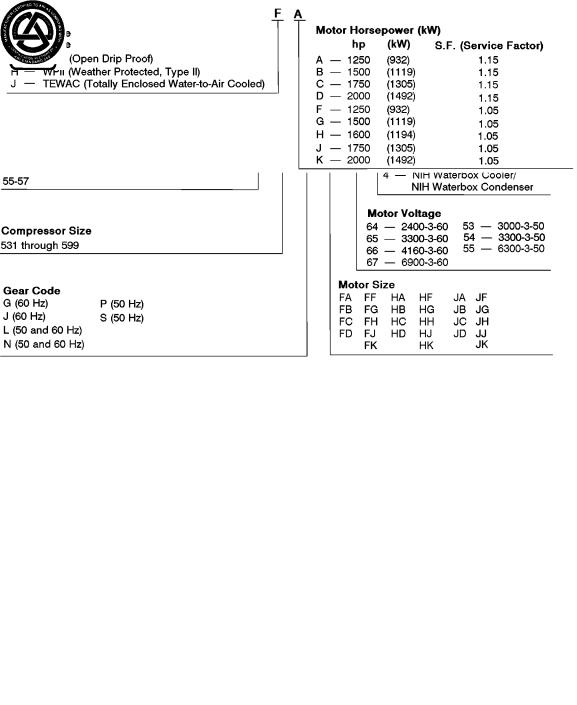
Chiller Identi®cation Label (Fig. 1) Ð The identi®cation label is located on the right side of the chiller control center panel. The label contains information on model number, refrigerant charge, rated voltage, etc.
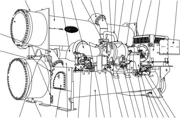
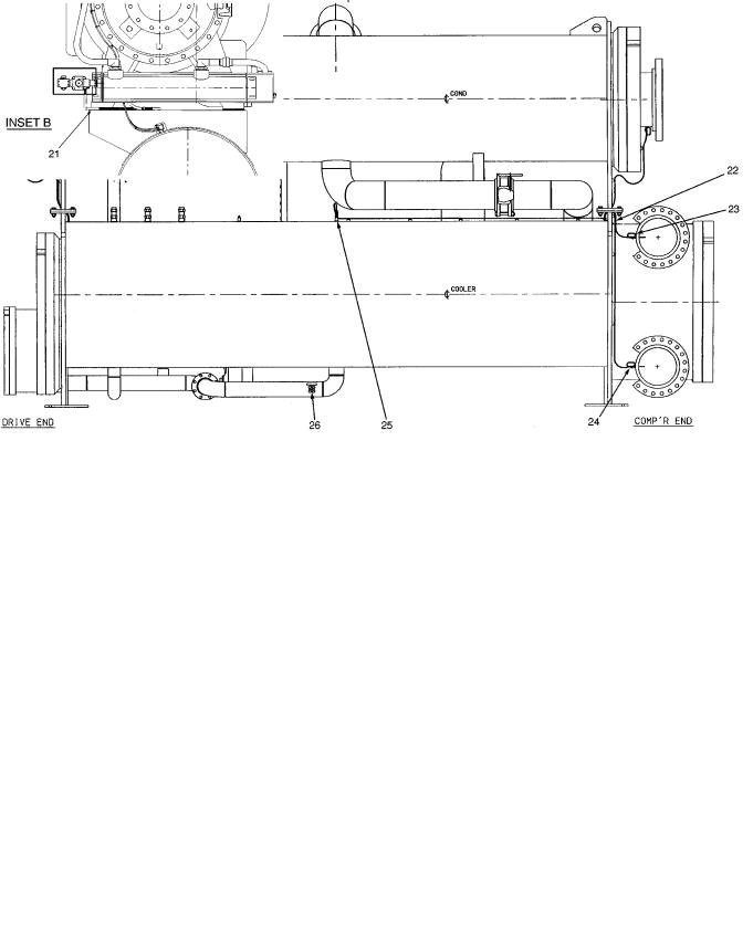
System Components (Fig. 2) Ð The components include the cooler and condenser heat exchangers in separate vessels, compressor, compressor and gear lubrication packages, control center, speed increaser economizer/storage vessel, motor, and starter. The compressor drive consists of an external gear (speed increaser) and an electric motor. All connections from pressure vessels have external threads to enable each component to be pressure tested with a threaded pipe cap during factory assembly.
Cooler Ð This vessel (also known as the evaporator) is located underneath the condenser, next to the economizer/ storage vessel. The cooler is maintained at lower temperature and pressure so that evaporating refrigerant can remove heat from water ¯owing through its internal tubes.
Condenser Ð The condenser operates at a higher temperature and pressure than the cooler and has water ¯owing through its internal tubes in order to remove heat from the refrigerant.
Compressor Ð This component maintains system temperature and pressure differences and moves the heatcarrying refrigerant from the cooler to the condenser.
Control Center Ð The control center is the user interface for controlling the chiller and regulates the chiller capacity as required to maintain proper leaving chilled water temperature. The control center:
·registers cooler, condenser, and lubricating system pressures
·shows chiller operating and alarm shutdown conditions
·records the total chiller operating hours and how many hours the chiller has been running
·sequences chiller start, stop, and recycle under microprocessor control
·provides access to other CCN (Carrier Comfort Network) devices
Motor Starter (Purchased Separately) Ð The starter allows the proper start and disconnect of electrical energy for the compressor-motor, oil pump, oil heater, and control panels.
Economizer/Storage Vessel Ð During normal operation, this vessel functions as an economizer, returning flash gas to the second stage of the compressor and increasing the efficiency of the refrigeration cycle. During periods of shutdown and service, the economizer/storage vessel can serve as a storage tank for the refrigerant.
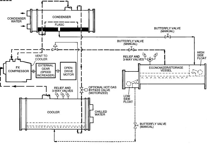
REFRIGERATION CYCLE (Fig. 3)
The 17EX chiller can be used to chill either water or brine. The data in this book applies to either application. Applications using corrosive brines may require using special tubes, tubesheet, and waterbox materials which are special order items.
5
LEGEND
NIH Ð Nozzle-In-Head
*Any available cooler size can be combined with any available condenser size.
NOTE: For details on motor size designations, see below.
ASME |
ARI (Air Conditioning |
`U' STAMP |
and Refrigeration |
|
Institute) |
|
PERFORMANCE |
|
CERTIFIED |
|
(60 Hz Only) |
|
Fig. 1 Ð Model Number Identi®cation |
6
40 |
1 |
2 |
3 |
4 |
5 |
6 |
7 |
8 |
9 |
10 |
11 |
12 |
13 |
14 |
39 
38
37 
36
35 
 15
15
|
34 |
33 |
32 |
31 |
30 |
29 |
28 |
27 |
26 |
25 |
24 |
23 |
22 |
21 |
20 |
19 |
18 |
17 |
16 |
|
|
|
|
|
LEGEND |
|
|
|
|
|
|
|
|
|
|
|
|
|
|
1 |
Ð Condenser |
|
|
|
|
|
|
22 |
Ð Oil Drain and Charging Valve |
|
|
|
|
||||||
2 |
Ð Cooler Suction Pipe |
|
|
|
|
|
23 |
Ð Oil Heater (Hidden) |
|
|
|
|
|
|
|||||
3 |
Ð Compressor Suction Elbow |
|
|
|
|
24 |
Ð Compressor Oil Pump |
|
|
|
|
|
|||||||
4 |
Ð Guide Vane Actuator |
|
|
|
|
|
25 |
Ð Compressor Oil Cooler/Filter |
|
|
|
|
|||||||
5 |
Ð Condenser Discharge Pipe |
|
|
|
|
26 |
Ð Local Interface Display Control Panel |
|
|
||||||||||
6 |
Ð Compressor Discharge Elbow |
|
|
|
|
27 |
Ð Cooler Relief Valves (Behind Compressor, |
|
|||||||||||
7 |
Ð Two-Stage Compressor |
|
|
|
|
|
|
Hidden) |
|
|
|
|
|
|
|
|
|
||
8 |
Ð Economizer Gas Line to Compressor |
|
|
|
28 |
Ð Economizer Storage Vessel |
|
|
|
|
|||||||||
9 |
Ð Compressor Housing Access Cover |
|
|
|
29 |
Ð Economizer/Storage Vessel Relief Valves |
|
||||||||||||
10 |
Ð High-Speed Coupling (Hidden) |
|
|
|
|
30 |
Ð Pumpout Unit |
|
|
|
|
|
|
|
|
||||
11 |
Ð External Gear (Speed Increaser) |
|
|
|
31 |
Ð Cooler |
|
|
|
|
|
|
|
|
|
||||
12 |
Ð Low-Speed Coupling (Hidden) |
|
|
|
|
32 |
Ð High Side Float Box Cover |
|
|
|
|
||||||||
13 |
Ð Open-Drive Compressor Motor |
|
|
|
|
33 |
Ð Cooler Waterbox Drain |
|
|
|
|
|
|||||||
14 |
Ð Compressor Motor Terminal Box |
|
|
|
34 |
Ð Take-Apart Connections |
|
|
|
|
|
||||||||
15 |
Ð Low-Side Float Box Cover |
|
|
|
|
35 |
Ð Cooler Marine Waterbox |
|
|
|
|
|
|||||||
16 |
Ð Gear Oil Pump |
|
|
|
|
|
36 |
Ð Cooler Waterbox Vent |
|
|
|
|
|
||||||
17 |
Ð Gear Oil Cooler/Filter |
|
|
|
|
|
37 |
Ð Condenser Waterbox Drain |
|
|
|
|
|||||||
18 |
Ð Refrigerant Charging/Service Valve |
|
|
|
38 |
Ð Refrigerant Liquid Line to Economizer/ |
|
||||||||||||
19 |
Ð Refrigerant Liquid Line to Cooler |
|
|
|
|
|
Storage Vessel |
|
|
|
|
|
|
|
|||||
20 |
Ð Power Panel |
|
|
|
|
|
39 |
Ð Condenser Marine Waterbox |
|
|
|
|
|||||||
21 |
Ð Oil Level Sight Glasses (2) |
|
|
|
|
40 |
Ð Condenser Waterbox Vent |
|
|
|
|
||||||||
17EX WITH EXTERNAL GEAR (SPEED INCREASER)
Fig. 2 Ð Typical 17EX Chiller Components
7

The chiller compressor continuously draws large quantities of refrigerant vapor from the cooler at a rate determined by the amount of guide vane opening. This compressor suction reduces the pressure within the cooler, allowing the liquid refrigerant to boil vigorously at a fairly low temperature (typically 38 to 42 F [3 to 6 C]).
The liquid refrigerant obtains the energy needed to vaporize by removing heat from the water or brine in the cooler tubes. The cold water or brine can then be used in air conditioning and/or other processes.
After removing heat from the water or brine, the refrigerant vapor enters the ®rst stage of the compressor, is compressed, and ¯ows into the compressor second stage. Here it is mixed with ¯ash-economizer gas and is further compressed.
Compression raises the refrigerant temperature above that of the water ¯owing through the condenser tubes. When the warm (typically 98 to 102 F [37 to 40 C]) refrigerant vapor comes into contact with the condenser tubes, the relatively cool condensing water (typically 85 to 95 F [29 to 35 C]) removes some of the heat, and the vapor condenses into a liquid.
The liquid refrigerant passes through an ori®ce into the FLASC chamber. The coolest condenser water ¯ows through the FLASC and allows a lower saturated temperature and pressure. Part of the entering liquid refrigerant will ¯ash to vapor once it has passed through the FLASC ori®ce, thereby cooling the remaining liquid. The vapor is then recondensed by the condenser water ¯owing through the FLASC chamber.
The subcooled liquid refrigerant drains into a high-side valve chamber that meters the refrigerant liquid into a ¯ash economizer chamber. Pressure in this chamber is intermediate between condenser and cooler pressures. At this lower pressure, some of the liquid refrigerant ¯ashes to gas, further cooling the remaining liquid. The ¯ash gas, having absorbed heat, is returned directly to the compressor second stage. Here it is mixed with discharge gas that is already compressed by the ®rst-stage impeller. Since the ¯ash gas has to pass through only half the compression cycle to reach condenser pressure, there is a savings in power.
The cooled liquid refrigerant in the economizer is metered through the low-side valve chamber, reducing the refrigerant pressure. Pressure in the cooler is lower than in the economizer. Some of the liquid ¯ashes as it passes through the low side ¯oat valve. The cycle is now complete.
OIL COOLING CYCLE
Compressor Oil Cooling Ð The compressor oil is water cooled. Water ¯ow through the oil cooler is manually adjusted by a plug valve to maintain an operating temperature at the reservoir of approximately 145 F (63 C). An oil heater in the reservoir helps to prevent oil from being diluted by the refrigerant. The heater is controlled by the PIC (Product Integrated Control) and is energized when the oil temperature is outside the operating temperature range of 150 to 160 F (66 to 71 C).
External Gear Oil Cooling Ð The external gear oil is also water cooled. Water ¯ow through the gear oil cooler is manually adjusted by a plug valve to maintain an operating temperature of approximately 130 F (54 C). If so equipped, an oil heater in the reservoir helps to maintain the oil temperature under cold ambient operating conditions. The heater is controlled by an internal thermostat.
LUBRICATION CYCLE
Compressor Lubrication Cycle (Refer to item numbers shown in Fig. 4) Ð The compressor oil pump and oil reservoir are contained in the compressor base. Oil is pumped through an oil cooler and ®lter to remove heat and any foreign particles. A portion of the oil is then directed to the shaft-end bearing and the shaft seal. The balance of the oil lubricates the thrust and journal bearings and the thrust end seal. The bearing and transmission oil returns directly to the reservoir to complete the cycle. Contact-seal oil leakage, however, is collected in an atmospheric ¯oat chamber to be pumped back to the main reservoir as the oil accumulates.
Oil may be charged into the compressor oil reservoir (Item 8) through a charging valve (Item 6) which also functions as an oil drain. If there is refrigerant in the chiller, however, a hand pump will be required for charging at this connection.
An oil-charging elbow (Item 3) on the seal-oil return chamber allows oil to be added without pumping. The seal-oil return pump (Item 4) automatically transfers the oil to the main reservoir. Sight glasses (11) on the reservoir wall permit observation of the oil level.
A motor-driven oil pump (Item 10) discharges oil to an oil cooler/®lter (Item 16) at a rate and pressure controlled by an oil regulator (Item 10). The differential oil pressure (bearing supply versus oil reservoir) is registered on the control panel.
Water ¯ow through the oil cooler is manually adjusted by a plug valve (Item 17) to maintain the oil at an operating temperature of approximately 145 F (63 C). During shutdown, the oil temperature is also maintained at 150 to 160 F (65 to 71 C) by an immersion heater (Item 7) in order to minimize absorption of refrigerant by the oil.
Upon leaving the cooler section of the oil cooler/®lter, the oil is ®ltered (Item 15) and a portion is directed to the sealend bearing (Item 1) and the shaft seal (Item 2). The remainder lubricates thrust (Item 14) and journal bearings (Item 12). Thrust bearing temperature is indicated on the PIC controls. Oil from both circuits returns by gravity to the reservoir.
The shaft seal of the open compressor drive must be kept full of lubrication oil, even when the chiller is not operating, to prevent loss of refrigerant.
If the chiller is not operating and the oil pump has not operated during the last 12 hours, the control system automatically runs the oil pump for one minute in order to keep the contact seal ®lled with oil.
IMPORTANT: If the control power is to be deenergized for more than one day, the chiller refrigerant should be pumped over to the economizer/storage vessel.
8
LEGEND
TXV Ð Thermostatic Expansion Valve Liquid
Liquid/Vapor
Vapor
*The FX compressor and the gear have a water cooled oil cooler.
Fig. 3 Ð Refrigeration, Cycle
External Gear Lubrication Cycle (Refer to Item numbers shown in Fig. 5) Ð Oil reservoir is contained in the gear base. The external gear oil pump is mounted below the gear with the cooler/®lter. Oil is pumped through an oil cooler/®lter to remove heat and any foreign particles. A portion of the oil is directed to the gear bearings and gear mesh spray. The remainder is bypassed to the sump. The bearing and transmission oil returns directly to the reservoir to complete the cycle.
Oil may be charged into the external gear oil reservoir as described in the section, External Gear Pre-Start Checks, page 51. Observe the oil level in the oil level glass (Item 4) on the reservoir wall.
A motor driven oil pump (Item 10) discharges oil to the oil cooler/®lter (Item 12). The pump has an internal pressure regulator to protect the pump in the event of an obstruction downstream. Water ¯ow through the oil cooler is manually adjusted by a plug valve (Item 14) to maintain the oil at an operating temperature of approximately 130 F (54 C).
Upon leaving the cooler section (Item 13) of the oil cooler/ ®lter, the oil is ®ltered (Item 11) and is directed to the pressure control valve (Item 7). Before entering the pressure control valve, the oil pressure (Item 16) and temperature (Item 8) are monitored by the PIC.
A portion of the oil then lubricates the gear bearings (Item 2). Another portion is directed through an ori®ce (Item 5) to the gear mesh spray (Item 3) to lubricate the gear mesh (Item 1) during operation. Oil from both circuits returns by gravity to the reservoir.
STARTERS
All starters, whether supplied by Carrier or the customer, must meet Carrier Starter Speci®cation Z-375. This speci- ®cation can be obtained from a Carrier Sales Representative. The purpose of this speci®cation is to ensure the compatibility of the starter and the chiller. Many styles of compatible starters are available, including solid-state , auto-transformer, full-voltage, and, in the case of low-voltage main power supply, wye-delta closed transition.
9

SHAFT DISPLACEMENT |
|
|
& BRG TEMP. CUTOUT |
|
1 |
CONNECTIONS |
COAST DOWN |
SEAL-END |
|
||
|
RESERVOIRS |
BEARING |
13 |
|
|
|
COMPRESSOR OIL |
|
|
|
PRESSURE LEAVING |
|
|
|
FILTER LINE |
|
|
|
12 |
|
2 |
|
|
SHAFT |
||
JOURNAL |
|
||
|
SEAL |
||
BEARING |
|
|
|
|
|
14 |
|
|
|
THRUST |
|
|
|
BEARING |
|
CHECK VALVE |
|
|
|
15 |
|
|
|
OIL FILTER |
|
|
|
16 |
|
|
|
OIL COOLER/ |
|
|
|
FILTER |
TO PIC |
|
|
|
|
||
17 |
CONTROLLER |
3 |
|
|
|||
PLUG VALVE |
8 |
||
OIL CHARGING |
|||
|
MAIN OIL |
||
|
ELBOW |
||
|
RESERVOIR |
|
11 |
|
|
|
|
4 |
|
|
|
|
|
PUMP, SEAL |
||
SIGHT |
|
|
|
|
||
|
|
|
|
OIL RETURN |
||
GLASSES |
|
|
|
|
|
|
10 |
TO POWER |
9 |
7 |
6 |
5 |
|
|
PANEL |
|
|
|
||
OIL PUMP |
OIL |
OIL |
DRAIN & |
COMPRESSOR OIL |
||
|
||||||
& PRESS. REGULATOR |
|
THERMISTOR |
HEATER |
CHARGING VALVE |
SUCTION PRESSURE |
Fig. 4 Ð 17EX Compressor Lubrication Cycle
10
1 |
Ð Gear Mesh |
8 |
Ð Oil Supply Temperature Thermistor |
2 |
Ð Bearings |
9 |
Ð Oil Pump Motor |
3 |
Ð Gear Mesh Spray |
10 |
Ð Oil Pump and Pressure Regulator |
4 |
Ð Oil Level Glass |
11 |
Ð Oil Filter |
5 |
Ð Ori®ce |
12 |
Ð Oil Cooler/Filter |
6 |
Ð Oil Supply Pressure |
13 |
Ð Oil Cooler |
|
Transducer |
14 |
Ð Plug Valve |
7 |
Ð Pressure Control Valve |
|
|
NOTE: The oil reservoir is at the base of the gear box.
Fig. 5 Ð External Gear Oil Lubrication Cycle (Plan View)
CONTROLS
De®nitions
ANALOG SIGNAL Ð An analog signal varies in proportion to the monitored source. It quanti®es values between operating limits. (Example: A temperature sensor is an analog device because its resistance changes in proportion to the temperature, generating many values.)
DIGITAL SIGNAL Ð A digital (discrete) signal is a 2-position representation of the value of a monitored source. (Example: A switch is a digital device because it only indicates whether a value is above or below a set point or boundary by generating an on/off, high/low, or open/closed signal.)
VOLATILE MEMORY Ð Volatile memory is memory incapable of being sustained if power is lost and subsequently restored.
The memories of the PSIO and LID modules are volatile. If the battery in a module is removed or damaged, all programming will be lost.
General Ð The 17EX externally geared open-drive centrifugal liquid chiller contains a microprocessor-based control center that monitors and controls all operations of the chiller. The microprocessor control system matches the cooling capacity of the chiller to the cooling load while providing state-of-the-art chiller protection. The system controls cooling load within the set point plus the deadband by sensing the leaving chilled water or brine temperature and regulating the inlet guide vane via a mechanically linked actuator motor. The guide vane is a variable ¯ow prewhirl assembly that controls the refrigeration effect in the cooler by regulating the amount of refrigerant vapor ¯ow into the compressor. An increase in guide vane opening increases capacity. A decrease in guide vane opening decreases capacity. Chiller protection is provided by the processor which monitors the digital and analog inputs and executes capacity overrides or safety shutdowns, if required.
11
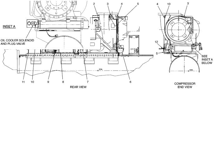
PIC System Components Ð The Product Integrated Control (PIC) is the control system on the chiller. See Table 1. The PIC controls the operation of the chiller by monitoring all operating conditions. The PIC can diagnose a problem and let the operator know what the problem is and what to check. It promptly positions the guide vanes to maintain leaving chilled water temperature. It can interface with auxiliary equipment such as pumps and cooling tower fans to turn them on only when required. It continually checks all safeties to prevent any unsafe operating condition. It also regulates the oil heater while the compressor is off and the hot gas bypass valve, if installed. See Fig. 6-10 for the locations of sensors, transducers, and other devices controlled and/or monitored by the PIC system.
The PIC can be interfaced with the Carrier Comfort Network (CCN) if desired. It can communicate with other PIC-equipped chillers and other CCN devices.
The PIC consists of 4 modules housed inside one of 3 locations: the control center, the power panel, or the starter cabinet. The component names and the control voltage of each location are listed below (also see Table 1):
·control center
Ð all extra low-voltage wiring (24 v or less)
REAR
·power panel
Ð115 v control voltage
Ðup to 600 v for oil pump power
·starter cabinet
Ðchiller power wiring (per job requirement)
Table 1 Ð Major PIC Components and
Panel Locations*
PIC COMPONENT |
PANEL |
|
LOCATION |
||
|
||
Processor Sensor Input/Output Module |
Control Center |
|
(PSIO) |
||
|
||
Starter Management Module (SMM) |
Starter Cabinet |
|
Local Interface Device (LID) |
Control Center |
|
6-Pack Relay Board |
Control Center |
|
8-Input Modules (Optional) |
Control Center |
|
4-In/2-Out Module |
Power Panel |
|
Oil Differential Pressure/Power Supply |
Control Center |
|
Module |
||
|
||
Oil Heater Contactor (1C) |
Power Panel |
|
Compressor Oil Pump Contactor (2C) |
Power Panel |
|
Gear Oil Pump Contactor (5C) |
Power Panel |
|
Hot Gas Bypass Relay (3C) (Optional) |
Power Panel |
|
Control Transformers (T1-T4) |
Power Panel |
|
Control and Oil Heater Voltage Selector (S1) |
Power Panel |
|
Temperature Sensors |
See Fig. 7 |
|
Pressure Transducers |
See Fig. 7 |
|
*See Fig. 6-10. |
|
|
|
|
LEGEND |
|
1 |
Ð Gear Oil Pressure Sensor |
6 |
Ð Compressor Oil Cooler |
11 Ð Motor Water Cooling Leak Detector |
2 |
Ð Thrust Bearing Temperature and |
|
Solenoid Conduit |
Cable (TEWAC Motor Only) |
3 |
Impeller Displacement Cable |
7 |
Ð Oil Heater Conduit |
12 Ð Discharge Oil Pressure Sensor |
Ð Discharge Temperature Sensor |
8 |
Ð Motor Space Heater Conduit |
TEWAC Ð Totally Enclosed Water-to-Air Cooled |
|
4 |
Ð Guide Vane Conduit and Cable |
9 |
Ð Gear Oil Temperature Sensor |
|
5 |
Ð High Pressure Cutout Switch |
10 |
Ð Motor High Temperature Switch Cable |
|
Fig. 6 Ð 17EX Controls and Sensor Locations
12
|
LEGEND |
|
|
13 |
Ð Condenser Pressure Transducer |
17 |
Ð Oil Pump Conduit |
14 |
Ð Condenser Entering Water |
18 |
Ð Oil Pump Sensor |
|
Temperature Sensor |
19 |
Ð PIC Control Panel |
15 |
Ð Condenser Entering and Leaving Water |
20 |
Ð Condenser Leaving Water |
|
Temperature Cable |
|
Temperature Sensor |
16 |
Ð Oil Suction Pressure Sensor |
21 |
Ð Gear Oil Cooler Solenoid Conduit |
LEGEND
22Ð Cooler Temperature Cable
23Ð Cooler Leaving Water Temperature Sensor
24Ð Cooler Entering Water Temperature Sensor
25Ð Cooler Pressure Sensor
26Ð Refrigerant Charging Valve
Fig. 6 Ð 17EX Controls and Sensor Locations (cont)
13
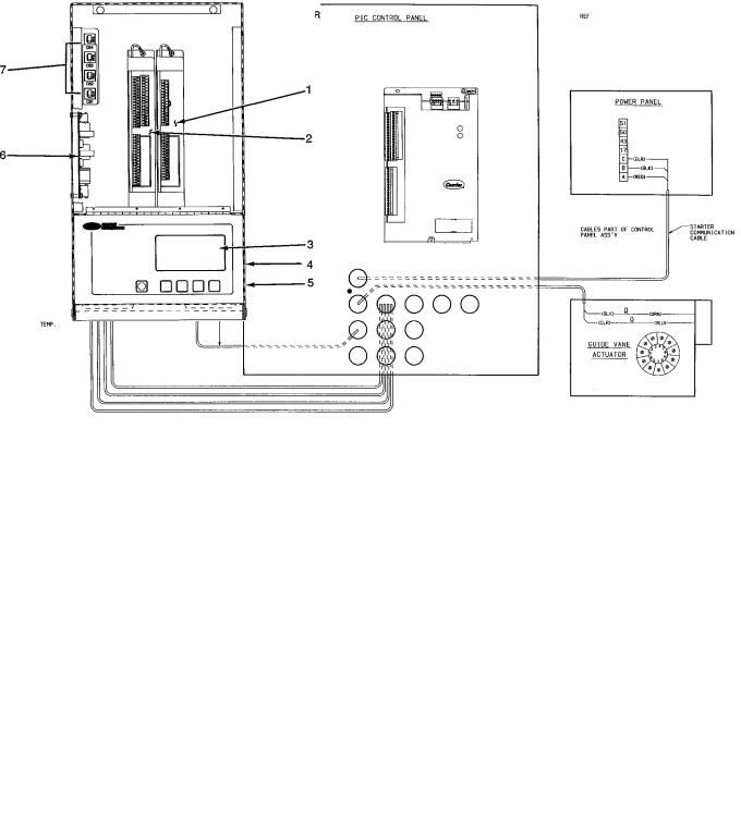
Fig. 6 Ð 17EX Controls and Sensor Locations (cont)
Fig. 7 Ð Control Sensors (Temperature)
Fig. 8 Ð Control Sensors
(Pressure Transducer, Typical)
|
|
|
LEGEND |
LID |
Ð |
Local Interface Device |
|
PIC |
Ð |
Product Integrated Controls |
|
PSIO |
Ð Processor Sensor Input/Output Module |
||
1 |
Ð |
Optional 8-Input Module for Spare Inputs to Control |
|
2 |
Ð |
Interface (One of Two Available) |
|
PSIO |
|||
3 |
Ð |
LID Input/Output Interface Panel Display |
|
4 |
Ð |
Oil Differential Pressure/Power Supply Module (Hidden) |
|
5 |
Ð |
LID Light (Hidden) |
|
6 |
Ð |
6-Pack Relay Board |
|
7 |
Ð |
Circuit Breakers (4) |
|
Fig. 9 Ð Control Center (Front View);
Shown with Options Module
14

15
|
LEGEND |
EQUIP GND Ð Equipment Ground |
|
GRD |
Ð Ground |
M |
Ð Motor |
TEWAC |
Ð Totally Enclosed Water-to- |
|
Air Cooled |
Fig. 10 Ð 17EX Chiller Power Panel and Controls Connections
PROCESSOR/SENSOR INPUT/OUTPUT MODULE (PSIO) Ð This module contains all the operating software needed to control the chiller. The 17EX uses 5 pressure transducers and 8 thermistors to sense pressures and temperatures. These inputs are connected to the PSIO module. The PSIO also provides outputs to the guide vane actuator, compressor and gear oil pumps, oil heater, hot gas bypass (optional), and alarm contact. The PSIO communicates with the LID, the SMM, and the optional 8-input modules for user interface and starter management.
STARTER MANAGEMENT MODULE (SMM) Ð This module is located within the starter cabinet. This module initiates PSIO commands for starter functions such as start/ stop of the compressor; start/stop of the condenser and chilled water pumps; start/stop of the tower fan, spare alarm contacts, and the shunt trip. The SMM monitors starter inputs such as ¯ow switches, line voltage, remote start contact, spare safety, condenser high pressure, oil pump interlock, motor current signal, starter 1M and run contacts, and the kW transducer input (optional). The SMM contains logic capable of safely shutting down the chiller if communication with the PSIO is lost.
LOCAL INTERFACE DEVICE (LID) Ð The LID is mounted to the control center and allows the operator to interface with the PSIO or other CCN devices. It is the input center for all local chiller set points, schedules, set-up functions, and options. The LID has a STOP button, an alarm light, 4 buttons for logic inputs, and a display. The function of the 4 buttons or ``softkeys'' are menu driven and are shown on the display directly above the key.
SIX-PACK RELAY BOARD (6-Pack Relay Board) Ð This device is a cluster of 6 pilot relays located in the control center. It is energized by the PSIO for the compressor oil pump, oil heater, alarm, optional hot gas bypass relay, auxiliary oil pump.
EIGHT-INPUT (8-Input) MODULES Ð One optional module is factory installed in the control center panel when ordered. There can be up to 2 of these modules per chiller with 8 spare inputs each. They are used whenever chilled water reset, demand reset, or reading a spare sensor is required. The sensors or 4 to 20 mA signals are ®eld-installed.
The spare temperature sensors must have the same temperature/resistance curve as the other temperature sensors on this unit. These sensors are rated 5,000 ohm at 75 F (25 C).
FOUR-IN/TWO-OUT (4-IN/2-OUT) MODULE Ð This module monitors and controls the external gear lubrication system. It energizes the gear oil pump and is located in the power panel.
OIL HEATER CONTACTOR (1C) Ð This contactor is located in the power panel and operates the heater at 115 v. It is controlled by the PIC to maintain oil temperature during chiller shutdown.
COMPRESSOR OIL PUMP CONTACTOR (2C) AND GEAR OIL PUMP CONTACTOR (5C) Ð These contactors are located in the power panel. They operate all 200 to 575-v oil pumps. The PIC energizes the contactor to turn on the oil pumps as necessary.
HOT GAS BYPASS CONTACTOR RELAY (3C) (Optional) Ð This relay, located in the power panel, controls the opening of the hot gas bypass valve. The PIC energizes the relay during low load, high lift conditions.
OIL AUXILIARY RELAY (4C) Ð This relay opens the oil cooler solenoid valve and interlocks the oil pump with the compressor (special order).
CONTROL TRANSFORMERS (T1-T4) Ð These transformers are located in the power panel and convert
incoming control voltage to either 21 vac power for the PSIO module and options modules, or 24 vac power for 3 power panel contactor relays and a control solenoid valve.
CONTROL AND OIL HEATER VOLTAGE SELECTOR (S1) Ð It is necessary to use 115 v incoming control power in the power panel. The switch must be set to the 115-v position.
OIL DIFFERENTIAL PRESSURE/POWER SUPPLY MODULE Ð This module, which is located in the control center, provides 5 vdc power for the transducers and LID backlight. This module outputs the difference between two pressure transducer input signals. The module subtracts oil supply pressure from transmission sump pressure and outputs the difference as an oil differential pressure signal to the PSIO. The PSIO converts this signal to differential oil pressure. To calibrate this reading, refer to the Troubleshooting, Checking Pressure Transducers section on page 84.
LID Operation and Menus (Fig. 11-17)
GENERAL
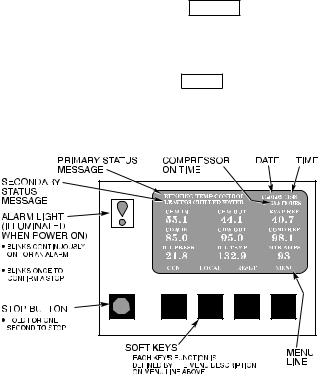
·The LID display automatically reverts to the default screen (Fig. 11) after 15 minutes if no softkey activity takes place and if the chiller is not in PUMPDOWN mode
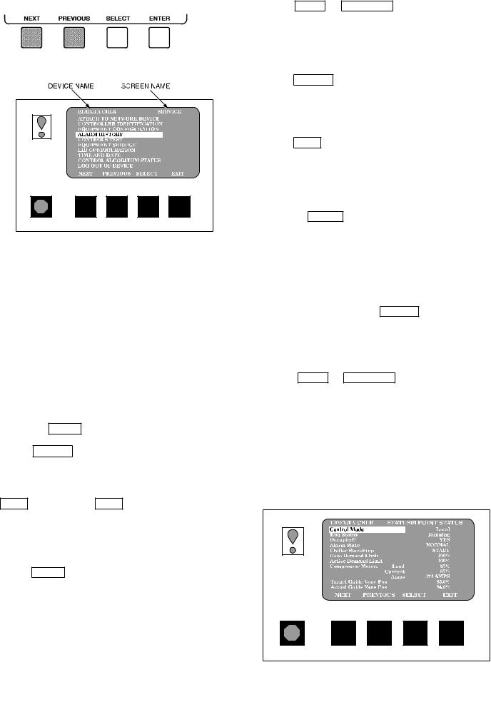
·When not displaying the default screen, the upper righthand corner of the LID displays the name of the screen that you have entered (Fig. 12).
·The LID may be con®gured in English or SI units, through the LID con®guration screen.
·Local Operation Ð Pressing the LOCAL softkey places
the PIC in LOCAL operation mode, and the control accepts modi®cation to programming from the LID only. The PIC uses the Local Time Schedule to determine chiller start and stop times.
·CCN Operation Ð Pressing the CCN softkey places the
PIC in the CCN operation mode, and the control accepts modi®cations from any CCN interface or module (with the proper authority), as well as the LID. The PIC uses the CCN time schedule to determine start and stop times.
Fig. 11 Ð LID Default Screen
ALARMS AND ALERTS Ð An alarm (*) or alert (!) status is indicated on the default screen and the status tables. An alarm (*) shuts down the compressor. An alert (!) noti®es the operator that an unusual condition has occurred. The chiller continues to operate when an alert is shown.
Alarms are indicated when the control center alarm light
(!) ¯ashes. The primary alarm message is viewed on the default screen and an additional, secondary, message and troubleshooting information are sent to the ALARM HISTORY table.
16
NOTE: When an alarm is detected, the LID default screen freezes (stops updating) at the time of alarm. The freeze enables the operator to view the chiller conditions at the time of the alarm. The status tables show the updated informa-
tion. Once all alarms have been cleared (by pressing the
RESET softkey), the default LID screen returns to normal
operation.
·Press NEXT or PREVIOUS to highlight the desired entry
· Press
·Press QUIT to leave the selected decision or ®eld without
Fig. 12 Ð LID Service Screen
LID DEFAULT SCREEN MENU ITEMS Ð To perform any of the operations described below, the PIC must be powered up and have successfully completed its self test.
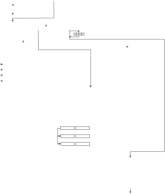
The default screen menu selection offers four options (STATUS, SCHEDULE, SETPOINT, and SERVICE). The STATUS menu allows viewing and limited calibration/ modi®cation of control points and sensors, relays and contacts, and the options board. The SCHEDULE menu allows viewing and modi®cation of the Local Control, CCN Control, and Ice Build time schedules. Numerous set points including Base Demand Limit, LCW, ECW, and Ice Build can be adjusted under the SETPOINT menu. The SERVICE menu can be used to revise alarm history, control test, control algorithm status, equipment con®guration, equipment service, time and date, attach to network, log out of device, controller identi®cation, and LID con®gurations. Figures 15 and 16 provide additional information on the menu structure.
Press the MENU softkey to select from the 4 options.
To view or change parameters within any menu structure,
use the SELECT softkey to choose the desired table or
item. The softkey modi®cation choices displayed will depend on whether the selected item is a discrete point, analog point, or an override point. Press the softkey that corresponds to your con®guration selection or press the
QUIT softkey. If the QUIT softkey is depressed, the
con®guration will not be modi®ed. Use the following softkeys to access and select the desired section.
MENU STRUCTURE Ð To perform any of the operations described below, the PIC must be powered up and have successfully completed its self test.
· Press MENU to select from the four available options.
·Press the softkey that corresponds to the desired menu structure.
·Or, press ENTER to leave the selected decision or ®eld and
TO VIEW OR CHANGE POINT STATUS (Fig. 13) Ð Point Status is the actual value of all of the temperatures, pressures, relays, and actuators sensed and controlled by the PIC.
1.On the Menu screen, press STATUS to view the list of Point
2.Press NEXT or PREVIOUS to highlight the desired status table. The list of tables is:
·STATUS01 Ð Status of control points and sensors
·STATUS02 Ð Status of relays and contacts
·STATUS03 Ð Status of both optional 8-input modules
and sensors
· STATUS04 Ð Gear oil temperature and pressure
Fig. 13 Ð Example of Point Status Screen
(Status01)
17
3. |
Press |
|
|
|
|
|
Override Indication Ð An override value is indicated by |
|||
|
|
|
|
|
|
|
``SUPVSR,'' ``SERVC,'' or ``BEST'' ¯ashing next to the point |
|||
|
|
|
|
|
|
|
||||
|
|
|
|
|
|
|
value on the Status table. |
|||
|
|
|
|
|
|
|
TO VIEW OR CHANGE TIME SCHEDULE OPERATION |
|||
|
|
|
|
|
|
|
(Fig. 14) |
|||
4. |
On the Point Status table press |
NEXT |
or |
|
|
. |
||||
1. On the Menu screen, press |
SCHEDULE |
|||||||||
|
|
|
|
|
|
|
||||
|
|
|
|
|
|
|
|
|
|
|
For Discrete Points Ð Press START or STOP ,
YES or NO , ON or OFF , etc. to select the desired state
For Analog Points Ð Press INCREASE or
5. Press
OVERRIDE OPERATIONS
NOTE: When overriding or changing metric values, it is necessary to hold the softkey down for a few seconds in order to see a value change, especially on kilopascal values.
To Remove an Override
1. On the Point Status table press NEXT or
2. Press
3.Press RELEASE to remove the override and return the point
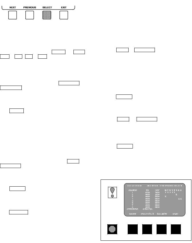
2.Press NEXT or PREVIOUS to highlight one of the following schedules.
OCCPC01S Ð LOCAL Time Schedule OCCPC02S Ð ICE BUILD Time Schedule OCCPC03-99S Ð CCN Time Schedule (Actual
3.
4. Press NEXT or PREVIOUS to highlight the de-
5.Press SELECT to access the highlighted period or override.
Fig. 14 Ð Example of Time Schedule
Operation Screen
18
|
|
|
|
|
|
|
|
|
|
DEFAULT SCREEN |
|
|
|
|
|
|
|
|
|
|
|
|
|
|
|
|
|
|
|
|
|
|
|
|||||||
|
|
|
|
|
CCN |
|
|
LOCAL |
|
|
|
RESET |
|
MENU |
(SOFTKEYS) |
|
|
|
|
|
|
|
|
|
|
|
|
|
||||||||||||
|
|
|
|
|
|
|
|
|
|
|
|
|
|
|
|
|
|
|
|
|
|
|
|
|
|
|
|
|
|
|
|
|
|
|
|
|
|
|
|
|
|
|
|
|
|
|
|
|
|
|
|
|
|
|
|
|
|
|
|
|
|
|
|
|
|
|
|
|
|
|
|
|
|
|
|
|
|
|
|
|
|
|
|
Start Chiller In CCN Control |
|
|
|
|
|
|
|
|
|
|
|
|
|
|
|
|
|
|
|
|
|
|
|
|
|
|
|
|
|
|
||||||||
|
|
|
|
|
|
|
|
|
|
|
|
|
|
|
|
|
|
|
|
|
|
|
|
|
|
|
|
|
|
|
|
|
|
|
|
|
|
|
|
|
|
|
|
|
|
|
|
|
|
|
|
|
|
|
|
|
|
|
|
|
|
|
|
|
|
|
|
|
|
|
|
|
|
|
|
|
|
|
|
|
|
|
|
Start Chiller In Local Control |
|
|
|
|
|
|
|
|
|
|
|
|
|
|
|
|
|
|
|
|
|
|
|
|
|
|
||||||||||||
|
|
Clear Alarms |
|
|
|
|
|
|
|
|
|
|
|
|
|
|
|
|
|
|
|
|
|
|
|
|
|
|
|
|
|
|
|
|
||||||
|
|
|
|
|
|
|
|
|
Access Main Menu |
|
|
|
|
|
|
|
|
|
|
|
|
|
|
|
|
|
||||||||||||||
|
|
|
|
|
|
|
|
|
|
|
|
|
|
|
|
|
|
|
|
|
|
|
|
|
|
|
|
|
|
|
|
|
|
|
|
|
||||
|
|
|
|
|
STATUS |
|
|
SCHEDULE |
|
|
SETPOINT |
|
SERVICE |
|
|
|
|
|
|
|
|
|
|
|
|
|
|
|
|
|
||||||||||
|
|
|
|
|
|
|
|
|
|
|
|
|
|
|
|
|
|
|
|
|
|
|
|
|
|
|
|
|
|
|
|
|
|
|
|
|
|
|||
|
|
|
|
|
|
|
|
|
|
|
|
|
|
|
|
|
|
|
1 |
|
2 3 4 |
(ENTER A 4-DIGIT PASSWORD) |
|
|
|
|
|
|||||||||||||
|
|
|
|
List the |
|
|
|
|
|
|
|
|
|
|
|
|
|
|
||||||||||||||||||||||
|
|
|
|
|
|
|
|
|
|
|
|
|
|
|
|
|
|
|
|
|
|
|
|
|
|
|
|
|
|
|
|
|
|
|
|
|||||
|
|
|
|
Status Tables |
|
|
|
|
|
|
|
|
|
|
|
|
|
|
|
|
|
|
|
|
|
|
|
|
|
|
|
|
List the Service Tables |
|||||||
|
|
|
|
|
|
|
|
|
|
|
|
|
|
|
|
|
|
|
|
|
|
|
|
|
|
|
|
|
Display the Setpoint Table |
|
|
|
|
|
||||||
|
|
|
|
STATUS 01 |
|
|
|
|
|
|
|
|
|
|
|
|
|
|
|
|
|
|
|
|
|
|
|
|
||||||||||||
|
|
|
|
STATUS 02 |
|
|
|
|
|
|
|
|
|
|
|
List the Schedules |
|
|
|
|
|
|
|
|
|
|
|
|
|
|||||||||||
|
|
|
|
|
|
|
|
|
|
|
|
|
|
|
|
|
|
|
|
|
|
|
|
|
|
|
|
|||||||||||||
|
|
|
|
STATUS 03 |
|
|
|
|
|
|
|
|
|
|
|
|
|
|
|
|
•Base Demand Limit |
|
|
|
||||||||||||||||
|
|
|
|
STATUS 04 |
|
|
|
|
|
|
|
|
|
|
|
|
|
|
|
|
|
|
|
|
|
|
|
|
|
|
|
|||||||||
|
|
|
|
|
|
|
|
|
|
|
|
|
|
|
|
|
|
|
|
|
|
|
|
|
|
|
|
•LCW Setpoint |
|
|
|
|||||||||
|
|
|
|
|
|
|
|
|
|
|
|
|
|
|
|
|
|
|
|
|
|
|
|
|
|
|
|
|
|
|
|
|
|
|
|
|||||
|
|
|
|
|
|
|
|
|
|
|
|
|
|
|
|
|
|
|
|
|
|
|
|
|
|
|
|
|
|
|
|
|
•ECW Setpoint |
|
|
|
||||
|
|
|
|
|
|
|
|
|
|
|
|
|
|
|
|
|
|
|
(SELECT A TABLE) |
|
|
|
|
|
•Ice Build Setpoint |
|
|
|
||||||||||||
|
|
NEXT |
|
PREVIOUS |
|
SELECT |
|
|
EXIT |
|
|
|
|
|
|
|
|
|||||||||||||||||||||||
|
|
|
|
|
|
|
|
|
|
|
|
|
|
|
|
|
|
|
|
|||||||||||||||||||||
|
|
|
|
|
|
|
|
|
|
|
|
|
|
|
|
|
|
|
(SELECT A POINT |
|
|
|
|
|
|
|
|
|
|
|
|
|
||||||||
|
|
NEXT |
|
PREVIOUS |
|
SELECT |
|
|
EXIT |
|
|
|
|
|
|
|
|
|
|
|
|
|
|
|||||||||||||||||
|
|
|
|
|
|
|
ON THE TABLE) |
|
Select the Setpoint |
|
|
|
|
|
||||||||||||||||||||||||||
|
|
|
|
|
|
|
|
|
|
|
|
|
|
|
|
|
|
|
|
|
|
|
|
|
||||||||||||||||
|
|
|
|
|
|
|
|
|
|
|
|
|
|
|
|
|
|
|
(MODIFY A |
|
|
|
|
|
|
|
|
|
|
|||||||||||
|
|
START |
|
STOP |
|
RELEASE |
|
ENTER |
|
|
|
|
|
|
NEXT |
|
PREVIOUS |
|
|
SELECT |
|
EXIT |
|
|||||||||||||||||
|
|
|
|
|
|
DISCRETE POINT) or |
|
|
|
|
|
|
||||||||||||||||||||||||||||
|
|
|
|
|
|
|
|
|
|
|
|
|
|
|
|
|
|
|
Modify the Setpoint |
|
|
|
|
|
||||||||||||||||
|
|
|
|
|
|
|
|
|
|
|
|
|
|
|
|
|
|
|
(MODIFY AN |
|
|
|
|
|
||||||||||||||||
|
|
INCREASE |
|
DECREASE |
|
RELEASE |
|
ENTER |
|
|
INCREASE |
|
DECREASE |
|
|
QUIT |
|
ENTER |
|
|||||||||||||||||||||
|
|
|
|
|
|
|
|
|
|
|
|
|
|
|
|
|
|
|
ANALOG POINT) or |
|
|
|
|
|
|
|||||||||||||||
|
|
|
|
|
|
|
|
|
|
|
|
|
|
|
|
|
|
|
||||||||||||||||||||||
|
|
|
|
|
|
|
|
|
|
|
|
|
|
|
|
|
|
|
(MODIFY CONTROL |
|
|
|
|
|
|
|
|
|
|
|
|
|
||||||||
|
|
ENABLE |
|
DISABLE |
|
RELEASE |
|
ENTER |
|
|
|
|
|
|
|
|
|
|
|
|
|
|
||||||||||||||||||
|
|
|
|
|
|
|
|
|
|
|
|
|
|
|
|
|
|
|
||||||||||||||||||||||
|
|
|
|
|
|
|
|
|
|
|
|
|
|
|
|
|
|
|
OPTIONS) |
|
|
|
|
|
|
|
|
|
|
|
|
|
|
|
|
|
||||
|
|
|
|
|
|
|
|
|
|
|
|
|
|
|
|
|
|
|
|
OCCPC01S - Local Time Schedule |
|
|
|
|
|
|
|
|
|
|||||||||||
|
|
|
|
|
|
|
|
|
|
|
|
|
|
|
|
|
|
|
|
OCCPC02S - Ice Build Time Schedule |
|
|
|
|
|
|||||||||||||||
|
|
|
|
|
|
|
|
|
|
|
|
|
|
|
|
|
|
|
|
OCCPC03S-99S - CCN Time Schedule |
|
|
|
|
|
|||||||||||||||
|
|
|
|
|
|
|
|
|
|
|
|
|
|
|
|
|
|
Select a Schedule |
|
|
|
|
|
|
|
|
|
|
|
|
|
|||||||||
|
|
|
|
|
|
|
|
|
|
|
|
|
|
|
|
|
|
|
NEXT |
|
|
PREVIOUS |
|
|
SELECT |
|
|
EXIT |
|
|
|
|
|
|
|
|||||
1
2
3
4
5
6
7
8 Override
Select a Time Period/Override
NEXT |
PREVIOUS |
Modify a Schedule Time |
|
INCREASE |
DECREASE |
Add/Eliminate a Day |
|
ENABLE |
DISABLE |
|
SELECT |
|
EXIT |
|
|
|
|
|
|
|
ENTER |
|
EXIT |
(ANALOG VALUES) |
|
|
|
|
|
|
ENTER |
|
EXIT |
(DISCRETE VALUES) |
• ALARM HISTORY
• CONTROL TEST
• CONTROL ALGORITHM STATUS
• EQUIPMENT CONFIGURATION
• EQUIPMENT SERVICE
• TIME AND DATE
• ATTACH TO NETWORK DEVICE
• LOG OUT OF DEVICE
• CONTROLLER IDENTIFICATION
• LID CONFIGURATION
Select a Service Table
NEXT |
|
PREVIOUS |
|
SELECT |
|
EXIT |
SEE FIGURE 16
Fig. 15 Ð 17EX LID Menu Structure
19
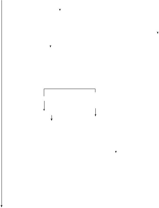
SERVICE TABLE |
|
|
|
|
|
|
|
|
|
|
|
|
|
|
|
|
|
|
|
|||||
NEXT |
|
PREVIOUS |
|
SELECT |
|
|
EXIT |
|
|
|
|
|
|
|
|
|
|
|
|
|||||
|
ALARM HISTORY |
|
|
|
|
|
|
|
|
|
|
|
|
|
|
|
|
|
|
|
||||
|
|
|
|
|
|
|
|
|
|
|
|
|
|
|
|
|
|
|
|
|
|
|
||
|
|
|
|
|
|
Display Alarm History |
|
|
|
|
|
|
|
|
|
|
|
|||||||
|
|
|
|
|
|
(The table holds up to 25 alarms |
|
|
|
|
|
|
|
|||||||||||
|
|
|
|
|
|
and alerts with the last alarm at |
|
|
|
|
|
|
|
|||||||||||
|
|
|
|
|
|
the top of the screen.) |
|
|
|
|
|
|
|
|
|
|
|
|||||||
|
CONTROL TEST |
|
|
|
|
|
|
|
|
|
|
List the Control Tests |
|
|
|
|||||||||
|
|
|
|
|
|
|
|
|
|
|
|
|
|
|
|
|
|
|
|
|
|
|
|
|
|
|
|
|
|
|
|
|
|
|
|
|
|
|
|
|
|
|
•Automated Test |
|
|
||||
|
CONTROL ALGORITHM STATUS |
|
|
|
|
|
|
|
|
•PSIO Thermistors |
|
|
||||||||||||
|
|
|
|
|
|
|
|
|
|
|
|
|
|
|
|
|
|
•Options Thermistor |
|
|
||||
|
|
|
|
|
|
|
|
|
|
|
|
|
|
|
|
|
|
|
|
|||||
|
|
|
|
|
|
|
|
|
|
|
|
|
|
|
|
|
|
•Transducers |
|
|
|
|||
|
|
|
|
|
|
|
|
|
|
|
|
|
|
|
|
|
|
|
|
|
||||
|
|
|
List the Control Algorithm Status Tables |
|
|
|
|
•Guide Vane Actuator |
|
|
||||||||||||||
|
|
|
MAINT01 (Capacity Control) |
|
|
|
|
|
|
|
|
•Pumps |
|
|
|
|||||||||
|
|
|
|
|
|
|
|
|
|
|
•Discrete Outputs |
|
|
|||||||||||
|
|
|
MAINT02 (Override Status) |
|
|
|
|
|
|
|
|
|
|
|||||||||||
|
|
|
|
|
|
|
|
|
|
|
•Pumpdown Lockout |
|
|
|||||||||||
|
|
|
MAINT03 (Surge/HGBP Status) |
|
|
|
|
|
|
|||||||||||||||
|
|
|
|
|
|
|
•Terminated Lockout |
|
|
|||||||||||||||
|
|
|
MAINT04 (Lead/Lag Status) |
|
|
|
|
|
|
|
|
|
|
|||||||||||
|
|
|
|
|
|
|
|
|
|
|
• FX Gear Oil Pump I/O |
|
|
|||||||||||
|
|
|
WSMDEFME (Water System Manager Control Status) |
|
|
|||||||||||||||||||
|
|
|
|
|
|
|
|
|
|
|||||||||||||||
|
|
|
OCCDEFM (Time Schedule Status) |
|
|
Select a Test |
|
|
|
|
|
|
|
|||||||||||
|
|
|
|
|
|
|
|
|
|
|
|
|
|
|
|
NEXT |
|
PREVIOUS |
|
|
SELECT |
|
EXIT |
|
|
|
Select a Table: |
|
|
|
|
|
|
|
|
|
|
|
|
|
|
|
|
|
|
|
|||
|
|
|
NEXT |
|
|
PREVIOUS |
|
|
SELECT |
|
|
EXIT |
|
|
|
|
|
|
|
|
||||
|
|
|
|
|
|
|
|
|
|
|
|
|
|
|
|
|
|
|
|
|
|
|
|
|
MAINT01 (Capacity Control Algorithm)
OCCDEFM (Time Schedule Status) MAINT02 (Override Status)\
MAINT03 (Surge/HGBP Status)
MAINT04 (LEAD/LAG Status)
WSMDEFM2 (Water System Manager Control Status)
Data Select Table
NEXT |
|
PREVIOUS |
|
SELECT |
|
EXIT |
Maintenance Table Data
OCCPC01S (Local Status)
OCCPC02S (CCN, ICE BUILD Status)
OCCPC03S (CCN Status)
|
EQUIPMENT CONFIGURATION |
List the Equipment Configuration Tables |
|
|
|
|
|
|
|
|
|
|
|||||||||||
|
|
|
|
|
|
|
|
|
|
|
|
|
|
|
|
|
|
|
|
|
|
|
|
|
|
|
|
|
|
|
|
• CONFIG |
|
|
|
|
|
|
|
|
|
|
|||||
|
|
|
|
|
|
|
|
• LEAD/LAG |
|
|
|
|
|
|
|
|
|
|
|||||
|
|
|
|
|
|
|
|
• OCCDEFCS |
|
|
|
|
|
|
|
|
|
||||||
|
|
|
|
|
|
|
|
• HOLIDEF |
|
|
|
|
|
|
|
|
|
|
|||||
|
|
|
|
|
|
|
|
• BRODEF |
|
|
|
|
|
|
|
|
|
|
|||||
|
|
|
|
|
|
|
|
• WSMALMDF |
|
|
|
|
|
|
|
|
|
||||||
|
|
|
|
|
|
|
|
• ALARMDEF |
|
|
|
|
|
|
|
|
|
||||||
|
|
|
|
|
|
|
|
• CONS_DEF |
|
|
|
|
|
|
|
|
|
||||||
|
|
|
|
|
|
|
|
• RUNT_DEF |
|
|
|
|
|
|
|
|
|
||||||
|
|
|
Select a Table |
|
|
|
|
|
|
|
|
|
|
|
|
|
|
|
|
||||
|
|
|
NEXT |
|
|
PREVIOUS |
|
|
SELECT |
|
|
EXIT |
|
|
|||||||||
|
|
|
|
Select a Parameter |
|
|
|
|
|
|
|
|
|
|
|||||||||
|
|
|
|
|
NEXT |
|
|
PREVIOUS |
|
SELECT |
|
|
EXIT |
|
|||||||||
CONTINUED |
|
|
Modify a Parameter |
|
|
|
|
|
|
|
|
|
(ANALOG |
||||||||||
ON NEXT PAGE |
|
|
INCREASE |
|
|
DECREASE |
|
QUIT |
|
|
ENTER |
VALUES) |
|||||||||||
|
|
|
|
|
|
|
|
|
|
|
|
|
|
|
|
|
|
|
|
|
|
|
(DISCRETE |
|
|
|
|
ENABLE |
|
|
DISABLE |
|
QUIT |
|
|
ENTER |
|||||||||||
|
|
|
|
|
|
|
|
|
VALUES) |
||||||||||||||
|
|
|
|
|
|
|
|
|
|
|
|
|
|
|
|
|
|
|
|
|
|
|
|
|
|
|
|
|
|
|
|
|
|
|
|
|
|
|
|
|
|
|
|
|
|
|
(DISCRETE |
|
|
|
|
|
YES |
|
|
|
NO |
|
|
QUIT |
|
|
ENTER |
||||||||
|
|
|
|
|
|
|
|
|
|
|
|
|
|
|
|
|
|
|
|
|
|
|
VALUES) |
|
|
|
|
|
|
|
|
|
|
|
|
|
|
|
|
|
|
|
|
|
|
|
|
Fig. 16 Ð 17EX Service Menu Structure
20
SERVICE MENU CONTINUED
FROM PREVIOUS PAGE
EQUIPMENT SERVICE (See Table 2, Examples 8, 9, and 10)
Service Tables: (See Note)
•SERVICE1
•SERVICE2
•SERVICE3
|
Select a Service Table |
|
|
|
|
|
|
|
|
|
|
|
|
|||||
|
NEXT |
|
PREVIOUS |
|
SELECT |
|
EXIT |
|
|
|
|
|
|
|
|
|
||
|
Select a Service Table Parameter |
|
|
|
|
|
|
|
|
|
|
|
||||||
|
NEXT |
|
PREVIOUS |
|
SELECT |
|
EXIT |
|
|
|
|
|
|
|
|
|
||
|
Modify a Service Table Parameter |
|
|
|
|
|
|
|
|
|
|
|
||||||
|
INCREASE |
|
DECREASE |
|
QUIT |
|
ENTER |
|
(ANALOG VALUES) |
|
|
|
||||||
|
|
|
|
|
|
|
|
|
|
|
|
|
|
|
|
|
|
|
|
ENABLE |
|
DISABLE |
|
QUIT |
|
ENTER |
|
(DISCRETE VALUES) |
|
|
|
||||||
|
|
|
|
|
|
|
|
|
|
|
|
|
|
|
|
|
|
|
|
NO |
|
|
YES |
|
|
QUIT |
|
ENTER |
|
(DISCRETE VALUES) |
|
|
|
||||
|
TIME AND DATE |
|
|
|
|
|
|
|
|
|
|
|
|
|||||
|
|
|
|
|
|
|
|
|
|
|
|
|
|
|
|
|
|
|
|
|
|
|
|
|
|
|
|
|
|
Display Time and Date Table: |
|
|
|||||
|
|
|
|
|
|
|
|
|
|
|
•To Modify — Time |
— Day of Week |
||||||
ATTACH TO NETWORK DEVICE |
|
|
|
|
|
— Date |
— Holiday Today |
|||||||||||
|
|
|
|
|
|
|
|
|
|
INCREASE |
|
DECREASE |
|
|
ENTER |
|
EXIT |
|
|
|
|
|
List Network Devices |
|
|
|
|
|
|
|
|
|
|
|
|||
|
|
|
|
•Local |
• Device 6 |
|
|
|
|
|
|
|
|
|
|
|
||
|
|
|
|
• Device 1 |
• Device 7 |
|
|
|
|
|
|
|
|
|
|
|
||
|
|
|
|
• Device 2 |
• Device 8 |
|
|
|
|
|
|
|
|
|
|
|
||
|
|
|
|
• Device 3 |
• Device 9 |
|
|
|
|
|
|
|
|
|
|
|
||
|
|
|
|
• Device 4 |
|
|
|
|
|
|
|
|
|
|
|
|
||
|
|
|
|
• Device 5 |
|
|
|
|
|
|
|
|
|
|
|
|
||
Select a Device |
|
|
|
|
|
|
|
||
NEXT |
|
PREVIOUS |
|
SELECT |
|
ATTACH |
|
||
Modify Device Address |
|
|
|
|
|
|
|
||
|
|
|
|
|
|
|
|||
INCREASE |
|
DECREASE |
|
ENTER |
|
EXIT |
|
||
•Use to attach LID to another CCN network or device
•Attach to "LOCAL" to enter this machine
•To upload new tables
|
LOG OUT OF DEVICE |
|
|
|
|
|
|
|
|
|
|
|
|
|||
|
|
|
|
|
|
|
|
Default Screen |
|
|
|
|
|
|
||
|
|
|
|
|
|
|
|
CCN |
|
|
LOCAL |
|
|
RESET |
|
MENU |
|
CONTROLLER IDENTIFICATION |
|
|
|
|
|
|
|
|
|
||||||
PSIO Controller |
|
|
|
|
|
|
|
|
|
|
|
|
||||
Identification Table |
|
|
|
|
|
|
|
|
|
|
|
|
||||
|
INCREASE |
|
DECREASE |
|
|
ENTER |
|
EXIT |
|
|
|
|
|
|
|
|
|
•To modify — PSIO CCN Address |
•To View — PSIO Software Version |
|
|||||||||||||
(last 2 digits on part number indicate software version)
LID CONFIGURATION
LID Configuration Table
INCREASE |
|
DECREASE |
|
ENTER |
•To Modify — LID CCN Address
— English or S.I. Metric Units
— Password
|
LEGEND |
CCN |
Ð Carrier Comfort Network |
HGBP Ð Hot Gas Bypass |
|
LID |
Ð Local Interface Device |
NOTE: SERVICE TABLES:
EXIT
•To View — LID Software Version
(last 2 digits of part number indicate software version)
SERVICE1: Ð Capacity Override
ÐType of Chilled Medium
ÐAlert Temperature
ÐFlow Veri®cation
ÐDeadband
ÐRecycle Restart Time
ÐSurge/HGBP Operation
ÐMotor Voltage, RLA, and Frequency
ÐStarter Type
ÐCondenser Freeze Safety
ÐSoft Stop Con®guration
ÐStart to Stop Timer
ÐGear Oil Pump Con®guration
SERVICE2: Ð 8-input Modules
Ð 20 mA Power Source
SERVICE3: Ð Proportional Inc each Band
ÐProportional Dec each Band
ÐProportional ECW Gain
ÐMaximum Guide Vane Opening
Fig. 16 Ð 17EX Service Menu Structure (cont)
21
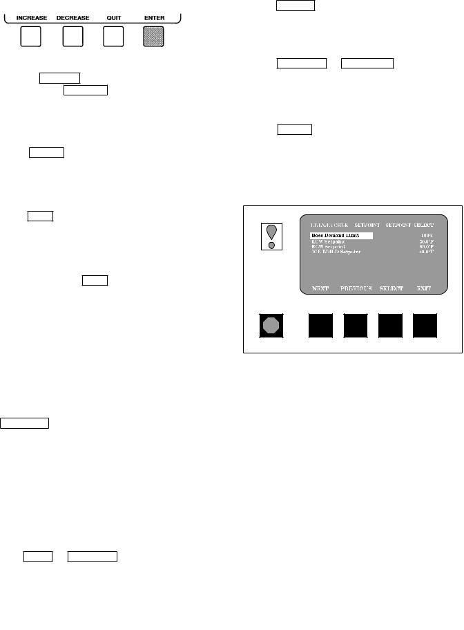
6. a. Press |
INCREASE |
or |
DECREASE |
to change the |
4. Press |
time values. Override values are in one-hour incre- |
|
||||
5. Press INCREASE or DECREASE to change the se-
b.Press ENABLE to select days in the day-of-week ®elds. Press DISABLE to eliminate days from the
6. Press ENTER to save the changes and return to the
7. Press ENTER to register the values and to move
8.
9. Either return to Step 4 to select another period or
override, or press EXIT again to leave the cur-
10.Holiday Designation (HOLIDEF table) may be found in the Service Operation section, page 42. You must assign the month, day, and duration for the holiday. The Broadcast function in the BRODEF table also must be enabled for holiday periods to function.
TO VIEW AND CHANGE SET POINTS (Fig. 17)
1. To view the Set Point table, at the Menu screen press
2.There are 4 set points on this screen: Base Demand Limit; LCW Set Point (leaving chilled water set point); ECW Set Point (entering chilled water set point); and ICE BUILD set point. Only one of the chilled water set points can be active at one time, and the type of set point is activated in the Service menu. ICE BUILD is also activated and con®gured in the Service menu.
3.Press NEXT or PREVIOUS to highlight the desired set
22
Fig. 17 Ð Example of Set Point Screen
SERVICE OPERATION Ð To view the menu-driven programs available for Service Operation, see the Service Operation section, page 42. For examples of LID display screens, see Table 2.
LEGEND FOR TABLE 2 Ð LID DISPLAY DATA
CCN |
Ð Carrier Comfort Network |
|
CHWR |
Ð Chilled Water Return |
|
CHWS |
Ð Chilled Water Supply |
|
Compr |
Ð Compressor |
|
Dec |
Ð Decrease |
|
Ecw |
Ð Entering Chilled Water |
|
HGBP |
Ð Hot Gas Bypass |
|
Inc |
Ð |
Increase |
LCW |
Ð Leaving Chilled Water |
|
mA |
Ð Milliamps |
|
P |
Ð Pressure |
|
PIC |
Ð |
Product Integrated Controls |
Refrig |
Ð |
Refrigerant |
T |
Ð Temperature |
|
Temp |
Ð Temperature |
|
Table 2 Ð LID Display Data
NOTES:
IMPORTANT: The following notes apply to all Table 2 examples.
1. Only 12 lines of information appear on the LID screen at any one
time. Press the NEXT or PREVIOUS softkey to highlight a point
or to view items below or above the current screen. If you have a
chiller with a backlit LID, press the NEXT softkey twice to page
forward; press the PREVIOUS softkey twice to page back.
2.To access the information shown in Examples 6 through 14, enter your 4-digit password after pressing the SERVICE softkey. If no
softkeys are pressed for 15 minutes, the LID automatically logs off (to prevent unrestricted access to PIC controls) and reverts to the default screen. If this happens, you must reenter your password to access the tables shown in Examples 6 through 14.
3.Terms in the Description column of these tables are listed as they appear on the LID screen.
4.The LID may be con®gured in English or Metric (SI) units using the LID CONFIGURATION screen. See the Service Operation section, page 42, for instructions on making this change.
5.The items in the Reference Point Name column do not appear on the LID screen. They are data or variable names used in CCN or Building Supervisor software. They are listed in these tables as a convenience to the operator if it is necessary to cross reference CCN/BS documentation or use CCN/BS programs. For more information, see the 17EX CCN literature.
6.Reference Point Names shown in these tables in all capital letters can be read by CCN and Building Supervisor software. Of these capitalized names, those preceded by an asterisk can also be changed (that is, written to) by the CCN, Building Supervisor software and the LID. Capitalized Reference Point Names preceded by two asterisks can be changed only from the LID. Reference Point Names in lower case type can be viewed by CCN or Building Supervisor software only by viewing the whole table.
7.Alarms and Alerts: An asterisk in the far right ®eld of a LID status screen indicates that the chiller is in an alarm state; an exclamation point in the far right ®eld of the LID screen indicates an alert state. The asterisk (or exclamation point) indicates that the value on that line has exceeded (or is approaching) a limit. For more information on alarms and alerts, see the Alarms and Alerts section, page 16.
EXAMPLE 1 Ð STATUS01 DISPLAY SCREEN
To access this display from the LID default screen:
1. Press MENU .
2.Press STATUS (STATUS01 will be highlighted).
3.Press SELECT .
|
DESCRIPTION |
RANGE |
|
UNITS |
REFERENCE POINT NAME |
|||||||||||||||
|
|
(ALARM HISTORY) |
||||||||||||||||||
|
|
|
|
|
||||||||||||||||
Control Mode |
Reset.Off. Local. CCN |
|
MODE |
|
|
|
||||||||||||||
Run Status |
Timeout. Recycle. Startup. |
|
STATUS |
|||||||||||||||||
|
|
Ramping. Running. Demand. |
|
|
|
|
|
|
|
|
|
|
|
|
|
|
|
|
|
|
|
|
Override. Shutdown. Abnormal. |
|
|
|
|
|
|
|
|
|
|
|
|
|
|
|
|
||
Occupied ? |
Pumpdown |
|
|
|
|
|
|
|
|
|
|
|
|
|
|
|
|
|
||
No/Yes |
|
|
OCC |
|
|
|
||||||||||||||
Alarm State |
Normal/Alarm |
|
|
ALM |
|
|
|
|||||||||||||
*Chiller Start/Stop |
Stop/Start |
|
|
CHIL |
|
|
|
|
S |
|
S |
|||||||||
Base Demand Limit |
40-100 |
|
% |
DLM |
|
|
|
|||||||||||||
*Active Demand Limit |
40-100 |
|
% |
DEM |
|
|
|
|
|
LIM |
||||||||||
Compressor Motor Load |
0-999 |
|
% |
CA |
|
|
|
|
|
|
|
|
L |
|
|
|
||||
|
Current |
0-999 |
|
% |
CA |
|
|
|
|
|
|
|
|
P |
|
|
|
|||
|
Amps |
0-9999 |
|
AMPS |
CA |
|
|
|
|
|
|
|
|
A |
|
|
|
|||
*Target Guide Vane Pos |
0-100 |
|
% |
GV |
|
|
|
|
|
|
|
TRG |
||||||||
Actual Guide Vane Pos |
0-100 |
|
% |
GV |
|
|
|
|
|
|
|
ACT |
||||||||
Water/Brine: Setpoint |
10-120 (±12.2-48.9) |
|
DEG F (DEG C) |
SP |
|
|
|
|
|
|
|
|
|
|
|
|
||||
* |
Control Point |
10-120 (±12.2-48.9) |
|
DEG F (DEG C) |
LCW |
|
|
STPT |
||||||||||||
Entering Chilled Water |
±40-245 (±40-118) |
|
DEG F (DEG C) |
ECW |
|
|
|
|||||||||||||
Leaving Chilled Water |
±40-245 (±40-118) |
|
DEG F (DEG C) |
LCW |
|
|
|
|||||||||||||
Entering Condenser Water |
±40-245 (±40-118) |
|
DEG F (DEG C) |
ECDW |
|
|
|
|||||||||||||
Leaving Condenser Water |
±40-245 (±40-118) |
|
DEG F (DEG C) |
LCDW |
|
|
|
|||||||||||||
Evaporator Refrig Temp |
±40-245 (±40-118) |
|
DEG F (DEG C) |
ERT |
|
|
|
|||||||||||||
Evaporator Pressure |
±6.7-420 (±46-2896) |
|
PSI (kPa) |
ERP |
|
|
|
|||||||||||||
Condenser Refrig Temp |
±40-245 (±40-118) |
|
DEG F (DEG C) |
CRT |
|
|
|
|||||||||||||
Condenser Pressure |
±6.7-420 (±46-2896) |
|
PSI (kPa) |
CRP |
|
|
|
|||||||||||||
Discharge Temperature |
±40-245 (±40-118) |
|
DEG F (DEG C) |
CMPD |
|
|
|
|||||||||||||
Bearing Temperature |
±40-245 (±40-118) |
|
DEG F (DEG C) |
MTRB |
|
|
|
|||||||||||||
Motor Winding Temp² |
±40-245 (±40-118) |
|
DEG F (DEG C) |
MTRW |
|
|
|
|||||||||||||
Motor Winding Hi |
Normal/Alarm |
|
|
MTRW |
|
|
|
|||||||||||||
|
Temp Cutout |
|
|
|
|
|
||||||||||||||
|
|
|
|
|
|
|
|
|
|
|
|
|
|
|
|
|
|
|
|
|
Oil Sump Temperature |
±40-245 (±40-118) |
|
DEG F (DEG C) |
OILT |
|
|
|
|||||||||||||
Oil Pressure Transducer² |
±6.7-420 (±46-2896) |
|
PSI (kPa) |
OILP |
|
|
|
|||||||||||||
Oil Pressure** |
±6.7-420 (±46-2896) |
|
PSID (kPad) |
OILPD |
|
|
|
|||||||||||||
Line Voltage: Percent |
0-999 |
|
% |
V |
|
|
|
P |
|
|
|
|||||||||
|
Actual |
0-9999 |
|
VOLTS |
V |
|
|
|
A |
|
|
|
||||||||
*Remote Contacts Input |
Off/On |
|
|
REMCON |
||||||||||||||||
Total Compressor Starts |
0-65535 |
|
|
c |
|
|
starts |
|||||||||||||
Starts in 12 Hours |
0-8 |
|
|
STARTS |
||||||||||||||||
Compressor Ontime |
0-500000.0 |
|
HOURS |
c |
|
|
hrs |
|
|
|
||||||||||
*Service Ontime |
0-32767 |
|
HOURS |
S |
|
|
|
HRS |
||||||||||||
*Compressor Motor kW |
0-9999 |
|
kW |
CKW |
|
|
|
|||||||||||||
²Information is applicable to hermetic chillers (19EX) only.
**Oil pressure is read directly from a differential pressure module on 17EX chillers.
NOTE: values preceded by an asterisk (*) can be forced (changed by an operator) from the LID screen or from another control device (such as a Carrier Comfort Network [CCN] terminal).
23
Table 2 Ð LID Display Data (cont)
EXAMPLE 2 Ð STATUS02 DISPLAY SCREEN
To access this display from the LID default screen: 1. Press MENU .
2.Press STATUS .
3.Scroll down to highlight STATUS02.
4.Press SELECT .
DESCRIPTION |
POINT TYPE |
UNITS |
REFERENCE POINT NAME |
||||||||||
INPUT |
OUTPUT |
|
(ALARM HISTORY) |
||||||||||
|
|
|
|||||||||||
Hot Gas Bypass Relay |
|
X |
OFF/ON |
HGBR |
|||||||||
*Chilled Water Pump |
|
X |
OFF/ON |
CHWP |
|||||||||
Chilled Water Flow |
X |
|
NO/YES |
EVFL |
|||||||||
*Condenser Water Pump |
|
X |
OFF/ON |
CDP |
|
|
|
|
|||||
Condenser Water Flow |
X |
|
NO/YES |
CDFL |
|||||||||
Compressor Start Relay |
|
X |
OFF/ON |
CMPR |
|||||||||
Compressor Start Contact |
X |
|
OPEN/CLOSED |
1CR |
|
|
|
|
|
|
AUX |
||
Compressor Run Contact |
X |
|
OPEN/CLOSED |
RUN |
|
|
|
|
AUX |
||||
Starter Fault Contact |
X |
|
OPEN/CLOSED |
STR |
|
|
|
|
FLT |
||||
Pressure Trip Contact |
X |
|
OPEN/CLOSED |
PRS |
|
|
|
|
TRIP |
||||
Single Cycle Dropout |
X |
|
NORMAL/ALARM |
V1 |
|
CYCLE |
|||||||
Oil Pump Relay |
|
X |
OFF/ON |
OILR |
|
|
|
|
|||||
Oil Heater Relay |
|
X |
OFF/ON |
OILH |
|
|
|
|
|||||
Motor Cooling Relay² |
|
X |
OFF/ON |
MTRC |
|||||||||
Auxiliary Oil Pump Relay |
|
X |
OFF/ON |
AUXOILR |
|||||||||
*Tower Fan Relay |
|
X |
OFF/ON |
TFR |
|
|
|
|
|||||
Compr. Shunt Trip Relay |
|
X |
OFF/ON |
TRIPR |
|||||||||
Alarm Relay |
|
X |
NORMAL/ALARM |
ALM |
|
|
|
|
|||||
Spare Prot Limit Input |
X |
|
ALARM/NORMAL |
SPR |
|
|
|
|
PL |
||||
|
|
|
|
|
|||||||||
|
|
|
|
|
|
|
|
|
|
|
|
|
|
²Information is applicable to hermetic machines only.
NOTE: values preceded by an asterisk (*) can be forced (changed by an operator) from the LID screen or from another control device (such as a Carrier Comfort Network [CCN] terminal).
EXAMPLE 3 Ð STATUS03 DISPLAY SCREEN
To access this display from the LID default screen:
1. Press MENU .
2.Press STATUS .
3.Scroll down to highlight STATUS03.
4.Press SELECT .
DESCRIPTION |
RANGE |
UNITS |
REFERENCE POINT NAME |
|||||||||
(ALARM HISTORY) |
||||||||||||
|
|
|
||||||||||
OPTIONS BOARD 1 |
|
|
|
|
|
|
|
|
|
|
|
|
*Demand Limit 4-20 mA |
4-20 |
mA |
DEM |
|
|
OPT |
||||||
*Temp Reset 4-20 mA |
4-20 |
mA |
RES |
|
|
OPT |
||||||
*Common CHWS Sensor |
±40-245 (±40-118) |
DEG F (DEG C) |
CHWS |
|
|
|
||||||
*Common CHWR Sensor |
±40-245 (±40-118) |
DEG F (DEG C) |
CHWR |
|
|
|
||||||
*Remote Reset Sensor |
±40-245 (±40-118) |
DEG F (DEG C) |
R |
|
RESET |
|||||||
*Temp Sensor Ð Spare 1 |
±40-245 (±40-118) |
DEG F (DEG C) |
SPARE1 |
|
||||||||
*Temp Sensor Ð Spare 2 |
±40-245 (±40-118) |
DEG F (DEG C) |
SPARE2 |
|
||||||||
*Temp Sensor Ð Spare 3 |
±40-245 (±40-118) |
DEG F (DEG C) |
SPARE3 |
|
||||||||
OPTIONS BOARD 2 |
|
|
|
|
|
|
|
|
|
|
|
|
*4-20 mA Ð Spare 1 |
4-20 |
mA |
SPARE1 |
|
M |
|||||||
*4-20 mA Ð Spare 2 |
4-20 |
mA |
SPARE2 |
|
M |
|||||||
*Temp Sensor Ð Spare 4 |
±40-245 (±40-118) |
DEG F (DEG C) |
SPARE4 |
|
||||||||
*Temp Sensor Ð Spare 5 |
±40-245 (±40-118) |
DEG F (DEG C) |
SPARE5 |
|
||||||||
*Temp Sensor Ð Spare 6 |
±40-245 (±40-118) |
DEG F (DEG C) |
SPARE6 |
|
||||||||
*Temp Sensor Ð Spare 7 |
±40-245 (±40-118) |
DEG F (DEG C) |
SPARE7 |
|
||||||||
*Temp Sensor Ð Spare 8 |
±40-245 (±40-118) |
DEG F (DEG C) |
SPARE8 |
|
||||||||
*Temp Sensor Ð Spare 9 |
±40-245 (±40-118) |
DEG F (DEG C) |
SPARE9 |
|
||||||||
NOTE: values preceded by an asterisk (*) can be forced (changed by an operator) from the LID screen or from another control device (such as a Carrier Comfort Network [CCN] terminal).
24

Table 2 Ð LID Display Data (cont)
EXAMPLE 4 Ð STATUS04 DISPLAY SCREEN
To access this display from the LID default screen: 1. Press MENU .
2.Press STATUS .
3.Scroll down to highlight STATUS04.
4.Press SELECT .
DESCRIPTION |
RANGE |
UNITS |
REFERENCE POINT NAME |
|
(ALARM HISTORY) |
||||
|
|
|
||
Main Gear Oil Pump |
|
OFF/ON |
MAINPMP1 |
|
Auxiliary Gear Oil Pump |
|
OFF/ON |
AUXPMP2 |
|
Gear Oil Pressure |
−6.7 to 420 (−46 to 2896) |
psi (kPa) |
GEAROILP |
|
Gear Oil Temperature |
−40 to 245 (−40 to 118) |
DEG F (DEG C) |
GEAROILT |
|
|
|
|
|
|
|
|
|
|
EXAMPLE 5 Ð SETPOINT DISPLAY SCREEN |
|
|
|
|
|||||
To access this display from the LID default screen: |
|
|
|
|
|
|
|
|
|
|||||
1. |
Press |
|
|
|
|
|
|
|
|
|
|
|
|
|
MENU |
. |
|
|
|
|
|
|
|
|
|
|
|
||
2. |
Press |
|
|
|
|
|
|
|
|
|
|
|
|
|
SETPOINT |
. |
|
|
|
|
|
|
|
|
|
|
|||
|
|
|
|
|
|
|
|
|
|
|
||||
|
DESCRIPTION |
CONFIGURABLE RANGE |
UNITS |
REFERENCE POINT NAME |
DEFAULT VALUE |
|||||||||
|
Base Demand Limit |
40-100 |
% |
DLM |
|
|
|
100 |
||||||
|
LCW Setpoint |
20-120 (±6.7-48.9) |
DEG F (DEG C) |
lcw |
|
|
|
sp |
50.0 (10.0) |
|||||
|
ECW Setpoint |
20-120 (±6.7-48.9) |
DEG F (DEG C) |
ecw |
|
|
|
sp |
60.0 (15.6) |
|||||
|
ICE BUILD Setpoint |
2060 (±6.7-15.6) |
DEG F (DEG C) |
ice |
|
sp |
40.0 ( 4.4) |
|||||||
|
|
|||||||||||||
|
|
|
|
|
|
|
|
|
|
|
|
|
|
|
25

Table 2 Ð LID Display Data (cont)
EXAMPLE 6 Ð CONFIGURATION (CONFIG) DISPLAY SCREEN
To access this display from the LID default screen: 1. Press MENU .
2.Press SERVICE .
3.Scroll down to highlight EQUIPMENT CONFIGURATION.
4.Press SELECT .
5.Scroll down to highlight CONFIG.
6.Press SELECT .
DESCRIPTION |
CONFIGURABLE RANGE |
UNITS |
REFERENCE POINT NAME |
DEFAULT VALUE |
|||||||||||||||||||||
RESET TYPE 1 |
|
|
|
|
|
|
|
|
|
|
|
|
|
|
|
|
|
|
|
|
|
|
|
|
|
Degrees Reset at 20 mA |
±30-30 (±17-17) |
DEG F (DEG C) |
deg |
|
|
|
|
|
|
|
|
|
|
20ma |
10D(6D) |
||||||||||
|
|
|
|
|
|
|
|
|
|||||||||||||||||
RESET TYPE 2 |
|
|
|
|
|
|
|
|
|
|
|
|
|
|
|
|
|
|
|
|
|
|
|
|
|
Remote Temp (No Reset) |
±40-245 (±40-118) |
DEG F (DEG C) |
res |
|
|
|
|
|
|
|
|
|
rt1 |
85 (29) |
|||||||||||
Remote Temp (Full Reset) |
±40-245 (±40-118) |
DEG F (DEG C) |
res |
|
|
|
|
|
|
|
|
|
rt2 |
65 (18) |
|||||||||||
Degrees Reset |
±30-30 (±17-17) |
DEG F (DEG C) |
res |
|
|
|
|
|
|
|
|
|
|
rt |
10D(6D) |
||||||||||
|
|
|
|
|
|
|
|
|
|
||||||||||||||||
RESET TYPE 3 |
|
|
|
|
|
|
|
|
|
|
|
|
|
|
|
|
|
|
|
|
|
|
|
|
|
CHW Delta T (No Reset) |
0-15 (0-8) |
DEG F (DEG C) |
restd |
|
|
|
|
|
1 |
10D(6D) |
|||||||||||||||
CHW Delta T (Full Reset) |
0-15 (0-8) |
DEG F (DEG C) |
restd |
|
|
|
|
|
2 |
0D(0D) |
|||||||||||||||
Degrees Reset |
±30-30 (±17-17) |
DEG F (DEG C) |
deg |
|
|
|
|
|
|
|
|
chw |
5D(3D) |
||||||||||||
|
|
|
|
|
|
|
|||||||||||||||||||
Select/Enable Reset Type |
0-3 |
|
res |
|
|
|
|
|
|
|
sel |
0 |
|||||||||||||
|
|
|
|
|
|
|
|
||||||||||||||||||
ECW CONTROL OPTION |
DISABLE/ENABLE |
|
ecw |
|
|
|
|
|
|
|
opt |
DISABLE |
|||||||||||||
Demand Limit At 20 mA |
40-100 |
% |
dem |
|
|
|
|
|
|
|
20ma |
40 |
|||||||||||||
20 mA Demand Limit Option |
DISABLE/ENABLE |
|
dem |
|
|
|
|
|
|
sel |
DISABLE |
||||||||||||||
|
|
|
|
|
|
|
|||||||||||||||||||
Auto Restart Option |
DISABLE/ENABLE |
|
astart |
DISABLE |
|||||||||||||||||||||
Remote Contacts Option |
DISABLE/ENABLE |
|
r |
|
|
contact |
DISABLE |
||||||||||||||||||
|
|
|
|||||||||||||||||||||||
Temp Pulldown Deg/Min |
2-10 |
|
tmp |
|
|
|
|
|
ramp |
3 |
|||||||||||||||
Load Pulldown %/Min |
5-20 |
|
kw |
|
|
ramp |
10 |
||||||||||||||||||
Select Ramp Type: |
0/1 |
|
ramp |
|
|
|
|
|
|
opt |
1 |
||||||||||||||
Temp = 0, Load = 1 |
|
|
|
|
|
|
|
|
|
|
|
|
|
|
|
|
|
|
|
|
|
|
|
|
|
Loadshed Group Number |
0-99 |
|
ldsgrp |
0 |
|||||||||||||||||||||
Loadshed Demand Delta |
0-60 |
% |
ldsdelta |
20 |
|||||||||||||||||||||
Maximum Loadshed Time |
0-120 |
MIN |
maxldstm |
60 |
|||||||||||||||||||||
CCN Occupancy Con®g: |
|
|
|
|
|
|
|
|
|
|
|
|
|
|
|
|
|
|
|
|
|
|
|
|
|
Schedule Number |
3-99 |
|
occpcxxe |
3 |
|||||||||||||||||||||
Broadcast Option |
DISABLE/ENABLE |
|
occbrcst |
DISABLE |
|||||||||||||||||||||
ICE BUILD Option |
DISABLE/ENABLE |
|
ibopt |
|
|
|
|
|
|
|
DISABLE |
||||||||||||||
ICE BUILD TERMINATION |
|
|
|
|
|
|
|
|
|
|
|
|
|
|
|
|
|
|
|
|
|
|
|
|
|
0 =Temp, 1 =Contacts, 2 =Both |
0-2 |
|
ibterm |
0 |
|||||||||||||||||||||
ICE BUILD Recycle Option |
DISABLE/ENABLE |
|
ibrecyc |
DISABLE |
|||||||||||||||||||||
|
|
|
|
|
|
|
|
|
|
|
|
|
|
|
|
|
|
|
|
|
|
|
|
|
|
NOTE: D = delta degrees.
26

Table 2 Ð LID Display Data (cont)
EXAMPLE 7 Ð LEAD/LAG CONFIGURATION DISPLAY SCREEN
To access this display from the LID default screen: 1. Press MENU .
2.Press SERVICE .
3.Scroll down to highlight EQUIPMENT CONFIGURATION.
4.Press SELECT .
5.Scroll down to highlight LEAD/LAG.
6.Press SELECT .
LEAD/LAG CONFIGURATION SCREEN
DESCRIPTION |
CONFIGURABLE RANGE |
UNITS |
REFERENCE POINT NAME |
DEFAULT VALUE |
|||||
LEAD/LAG SELECT |
|
|
|
|
|
|
|
|
|
DISABLE =0, LEAD =1, |
0-3 |
|
leadlag |
0 |
|||||
LAG =2, STANDBY =3 |
|
|
|
|
|
|
|
|
|
Load Balance Option |
DISABLE/ENABLE |
|
loadbal |
DISABLE |
|||||
Common Sensor Option |
DISABLE/ENABLE |
|
commsens |
DISABLE |
|||||
LAG Percent Capacity |
25-75 |
% |
lag |
|
|
|
per |
50 |
|
|
|
|
|||||||
LAG Address |
1-236 |
|
lag |
|
|
|
add |
92 |
|
|
|
|
|||||||
LAG START Timer |
2-60 |
MIN |
lagstart |
10 |
|||||
LAG STOP Timer |
2-60 |
MIN |
lagstop |
10 |
|||||
PRESTART FAULT Timer |
0-30 |
MIN |
pre¯t |
|
|
5 |
|||
STANDBY Chiller Option |
DISABLE/ENABLE |
|
stndopt |
DISABLE |
|||||
STANDBY Percent Capacity |
25-75 |
% |
stnd |
|
|
per |
50 |
||
|
|
||||||||
STANDBY Address |
1-236 |
|
stnd |
|
|
add |
93 |
||
|
|
|
|||||||
|
|
|
|
|
|
|
|
|
|
27

Table 2 Ð LID Display Data (cont)
EXAMPLE 8 Ð SERVICE1 DISPLAY SCREEN
To access this display from the LID default screen: 1. Press MENU .
2.Press SERVICE .
3.Scroll down to highlight EQUIPMENT SERVICE.
4.Press SELECT .
5.Scroll down to highlight SERVICE1.
6.Press SELECT .
DESCRIPTION |
CONFIGURABLE RANGE |
UNITS |
REFERENCE POINT NAME |
DEFAULT VALUE |
|||||||||||||||||||||||||||||||||||
Motor Temp Override* |
150-200 (66-93) |
DEG F (DEG C) |
mt |
|
|
|
|
|
|
|
|
|
|
|
|
|
|
|
over |
200 (93) |
|||||||||||||||||||
Cond Press Override |
90-200 (620-1379) |
PSI (kPa) |
cp |
|
|
|
|
|
|
|
|
|
|
|
|
|
|
|
|
|
|
|
|
over |
125 (862) |
||||||||||||||
Refrig Override Delta T |
2-5 (1-3) |
DEG F (DEG C) |
ref |
|
|
|
|
|
|
|
|
|
|
|
|
|
|
|
over |
3D (1.6D) |
|||||||||||||||||||
Chilled Medium |
Water/Brine |
|
medium |
WATER |
|||||||||||||||||||||||||||||||||||
Brine Refrig Trippoint |
8-40 (±13.3-4) |
DEG F (DEG C) |
br |
|
|
|
|
|
|
|
|
|
|
|
|
trip |
33 (1) |
||||||||||||||||||||||
|
|
|
|
|
|
|
|
|
|
|
|
||||||||||||||||||||||||||||
Compr Discharge Alert |
125-200 (52-93) |
DEG F (DEG C) |
cd |
|
|
|
|
|
|
|
|
|
|
|
|
|
alert |
200 (93) |
|||||||||||||||||||||
Bearing Temp Alert |
165-210 (74-99) |
DEG F (DEG C) |
tb |
|
|
|
|
|
|
|
|
|
|
|
alert |
175 (79) |
|||||||||||||||||||||||
|
|
|
|
|
|
|
|
|
|
|
|||||||||||||||||||||||||||||
Water Flow Verify Time |
0.5-5 |
MIN |
w¯ow |
|
|
|
|
|
|
|
|
|
|
t |
5 |
||||||||||||||||||||||||
Oil Press Verify Time |
15-300 |
SEC |
oilpr |
|
|
|
|
|
|
|
|
|
|
|
|
|
t |
15 |
|||||||||||||||||||||
|
|
|
|
|
|
|
|
|
|
|
|
||||||||||||||||||||||||||||
Water/Brine Deadband |
0.5-2.0 (0.3-1.1) |
DEG F (DEG C) |
cw |
|
|
|
|
|
|
|
|
|
|
|
|
|
db |
1.0 (0.6) |
|||||||||||||||||||||
Recycle Restart Delta T |
2.0-10.0 (1.1-5.6) |
DEG F (DEG C) |
rcycrdt |
5 (2.8) |
|||||||||||||||||||||||||||||||||||
Recycle Shutdown Delta |
0.5-4.0 (.27-2.2) |
|
rcycsdt |
1.0 (0.6) |
|||||||||||||||||||||||||||||||||||
Surge Limit/HGBP Option |
0/1 |
|
srg |
|
|
|
|
|
|
|
|
|
|
|
|
|
|
|
|
hgbp |
0 |
||||||||||||||||||
Select: Surge=0, HGBP=1 |
|
|
|
|
|
|
|
|
|
|
|
|
|
|
|
|
|
|
|
|
|
|
|
|
|
|
|
|
|
|
|
|
|
|
|
|
|
|
|
Surge/HGBP Delta T1 |
0.5-15 (0.3-8.3) |
DEG F (DEG C) |
hgb |
|
|
|
|
|
|
|
|
|
|
|
|
dt1 |
1.5 (0.8) |
||||||||||||||||||||||
Surge/HGBP Delta P1 |
30-170 (207-1172) |
PSI (kPa) |
hgb |
|
|
|
|
|
|
|
|
|
|
|
|
dp1 |
50 (345) |
||||||||||||||||||||||
Min. Load Points (T1/P1) |
|
|
|
|
|
|
|
|
|
|
|
|
|
|
|
|
|
|
|
|
|
|
|
|
|
|
|
|
|
|
|
|
|
|
|
|
|
|
|
Surge/HGBP Delta T2 |
0.5-15 (0.3-8.3) |
DEG F (DEG C) |
hgb |
|
|
|
|
|
|
|
|
|
|
|
|
dt2 |
10 (5.6) |
||||||||||||||||||||||
Surge/HGBP Delta P2 |
30-170 (207-1172) |
PSI (kPa) |
hgb |
|
|
|
|
|
|
|
|
|
|
|
|
dp2 |
85 (586) |
||||||||||||||||||||||
Full Load Points (T2/P2) |
|
|
|
|
|
|
|
|
|
|
|
|
|
|
|
|
|
|
|
|
|
|
|
|
|
|
|
|
|
|
|
|
|
|
|
|
|
|
|
Surge/HGBP Deadband |
1-3 (0.6-1.6) |
DEG F (DEG C) |
hgb |
|
|
|
|
|
|
|
|
|
|
|
dp |
1 (0.6) |
|||||||||||||||||||||||
|
|
|
|
|
|
|
|
|
|
|
|||||||||||||||||||||||||||||
Surge Delta Percent Amps |
10-50 |
% |
surge |
|
|
|
|
|
|
|
|
a |
25 |
||||||||||||||||||||||||||
Surge Time Period |
1-5 |
MIN |
surge |
|
|
|
|
|
|
|
|
t |
2 |
||||||||||||||||||||||||||
|
|
|
|
|
|
|
|||||||||||||||||||||||||||||||||
Demand Limit Source |
0/1 |
|
dem |
|
|
|
|
|
|
|
|
|
|
|
|
src |
0 |
||||||||||||||||||||||
Select: Amps=0, Load=1 |
|
|
|
|
|
|
|
|
|
|
|
|
|
|
|
|
|
|
|
|
|
|
|
|
|
|
|
|
|
|
|
|
|
|
|
|
|
|
|
Amps Correction Factor |
1-8 |
|
corfact |
3 |
|||||||||||||||||||||||||||||||||||
Motor Rated Load Amps |
1-9999 |
AMPS |
a |
|
|
|
|
|
|
|
fs |
|
|
|
|
|
|
|
200 |
||||||||||||||||||||
Motor Rated Line Voltage |
1-9999 |
VOLTS |
v |
|
|
|
fs |
|
|
|
|
|
|
|
460 |
||||||||||||||||||||||||
Meter Rated Line kW |
1-9999 |
kW |
kw |
|
|
|
|
|
|
|
|
|
|
fs |
600 |
||||||||||||||||||||||||
|
|
|
|
|
|
|
|
|
|||||||||||||||||||||||||||||||
Line Frequency |
0/1 |
HZ |
freq |
|
|
|
|
|
|
|
|
|
|
|
|
|
|
|
|
|
0 |
||||||||||||||||||
Select: 0=60 Hz, 1=50 Hz |
|
|
|
|
|
|
|
|
|
|
|
|
|
|
|
|
|
|
|
|
|
|
|
|
|
|
|
|
|
|
|
|
|
|
|
|
|
|
|
Compr Starter Type |
REDUCE/FULL |
|
starter |
REDUCE |
|||||||||||||||||||||||||||||||||||
Condenser Freeze Point |
±20-35 (±28.9-1.7) |
DEG F (DEG C) |
cdfreeze |
34 (1) |
|||||||||||||||||||||||||||||||||||
Soft Stop Amps Threshold |
40-100 |
% |
softstop |
100 |
|||||||||||||||||||||||||||||||||||
Stop to Start Timer |
3-50 |
MIN |
stopmtr |
20 |
|||||||||||||||||||||||||||||||||||
External Gear Option |
|
ENABLE/DSABLE |
exg |
|
|
|
|
|
|
|
|
|
|
|
|
|
|
|
opt |
ENABLE |
|||||||||||||||||||
Mechanical Gear Oil Pump |
|
ENABLE/DSABLE |
mech |
|
|
|
|
|
|
|
|
pmp |
DSABLE |
||||||||||||||||||||||||||
Auxiliary Gear Oil Pump |
|
ENABLE/DSABLE |
aux |
|
|
|
|
|
|
|
|
|
|
|
|
|
|
|
pmp |
DSABLE |
|||||||||||||||||||
Gear Oil Pressure Alert |
15-20 (103-138) |
PSI (kPa) |
gearp |
|
|
|
|
|
|
|
al |
15 (103) |
|||||||||||||||||||||||||||
Gear Oil Temperature Alert |
130-145 (54-63) |
DEG F (DEG C) |
geart |
|
|
|
|
al |
130 (54) |
||||||||||||||||||||||||||||||
|
|
|
|
||||||||||||||||||||||||||||||||||||
|
|
|
|
|
|
|
|
|
|
|
|
|
|
|
|
|
|
|
|
|
|
|
|
|
|
|
|
|
|
|
|
|
|
|
|
|
|
|
|
*Information is applicable to hermetic machines (19EX) only. NOTE: D = delta degrees.
28

Table 2 Ð LID Display Data (cont)
EXAMPLE 9 Ð SERVICE2 DISPLAY SCREEN
To access this display from the LID default screen: 1. Press MENU .
2.Press SERVICE .
3.Scroll down to highlight EQUIPMENT SERVICE.
4.Press SELECT .
5.Scroll down to highlight SERVICE2.
6.Press SELECT .
DESCRIPTION |
CONFIGURABLE RANGE |
UNITS |
REFERENCE POINT NAME |
DEFAULT VALUE |
||||||||||||||||
OPTIONS BOARD 1 |
|
|
|
|
|
|
|
|
|
|
|
|
|
|
|
|
|
|
|
|
20 mA POWER CONFIGURATION |
|
|
|
|
|
|
|
|
|
|
|
|
|
|
|
|
|
|
|
|
External = 0, Internal = 1 |
|
|
|
|
|
|
|
|
|
|
|
|
|
|
|
|
|
|
|
|
RESET 20 mA Power Source |
0,1 |
|
res |
|
|
|
|
|
|
|
|
|
|
|
20 ma |
0 |
||||
DEMAND 20 mA Power Source |
0,1 |
|
dem |
|
|
|
|
|
|
|
|
20 ma |
0 |
|||||||
|
|
|
|
|
|
|
|
|
||||||||||||
SPARE ALERT ENABLE |
|
|
|
|
|
|
|
|
|
|
|
|
|
|
|
|
|
|
|
|
Disable = 0, 1 = High Alert, 2 = Low Alert, |
|
|
|
|
|
|
|
|
|
|
|
|
|
|
|
|
|
|
|
|
3 = High Alarm, 4 = Low Alarm |
|
|
|
|
|
|
|
|
|
|
|
|
|
|
|
|
|
|
|
|
Temp = Alert Threshold |
|
|
|
|
|
|
|
|
|
|
|
|
|
|
|
|
|
|
|
|
CHWS Temp Enable |
0-4 |
|
chws |
|
|
|
|
|
en |
0 |
||||||||||
CHWS Temp Alert |
±40-245 (±40-118) |
DEG F (DEG C) |
chws |
|
|
|
|
|
al |
245 (118) |
||||||||||
CHWR Temp Enable |
0-4 |
|
chwr |
|
|
|
|
en |
0 |
|||||||||||
CHWR Temp Alert |
±40-245 (±40-118) |
DEG F (DEG C) |
chwr |
|
|
|
|
|
al |
245 (118) |
||||||||||
Reset Temp Enable |
0-4 |
|
rres |
|
|
|
|
en |
0 |
|||||||||||
Reset Temp Alert |
±40-245 (±40-118) |
DEG F (DEG C) |
rres |
|
|
|
al |
245 (118) |
||||||||||||
Spare Temp 1 Enable |
0-4 |
|
spr1 |
|
|
|
en |
0 |
||||||||||||
Spare Temp 1 Alert |
±40-245 (±40-118) |
DEG F (DEG C) |
spr1 |
|
|
|
|
al |
245 (118) |
|||||||||||
Spare Temp 2 Enable |
0-4 |
|
spr2 |
|
|
|
en |
0 |
||||||||||||
Spare Temp 2 Alert |
±40-245 (±40-118) |
DEG F (DEG C) |
spr2 |
|
|
|
|
al |
245 (118) |
|||||||||||
Spare Temp 3 Enable |
0-4 |
|
spr3 |
|
|
|
en |
0 |
||||||||||||
Spare Temp 3 Alert |
±40-245 (±40-118) |
DEG F (DEG C) |
spr3 |
|
|
|
|
al |
245 (118) |
|||||||||||
|
|
|
|
|||||||||||||||||
OPTIONS BOARD 2 |
|
|
|
|
|
|
|
|
|
|
|
|
|
|
|
|
|
|
|
|
20 mA POWER CONFIGURATION |
|
|
|
|
|
|
|
|
|
|
|
|
|
|
|
|
|
|
|
|
External = 0, Internal = 1 |
|
|
|
|
|
|
|
|
|
|
|
|
|
|
|
|
|
|
|
|
SPARE 1 20 mA Power Source |
0,1 |
|
sp1 |
|
|
20 ma |
0 |
|||||||||||||
SPARE 2 20 mA Power Source |
0,1 |
|
sp2 |
|
|
20 ma |
0 |
|||||||||||||
|
|
|
||||||||||||||||||
SPARE ALERT ENABLE |
|
|
|
|
|
|
|
|
|
|
|
|
|
|
|
|
|
|
|
|
Disable = 0, 1 = High Alert, 2 = Low Alert, |
|
|
|
|
|
|
|
|
|
|
|
|
|
|
|
|
|
|
|
|
3 = High Alarm, 4 = Low Alarm |
|
|
|
|
|
|
|
|
|
|
|
|
|
|
|
|
|
|
|
|
Temp = Alert Threshold |
|
|
|
|
|
|
|
|
|
|
|
|
|
|
|
|
|
|
|
|
Spare Temp 4 Enable |
0-4 |
|
spr4 |
|
|
|
en |
0 |
||||||||||||
Spare Temp 4 Alert |
±40-245 (±40-118) |
DEG F (DEG C) |
spr4 |
|
|
|
|
al |
245 (118) |
|||||||||||
Spare Temp 5 Enable |
0-4 |
|
spr5 |
|
|
|
en |
0 |
||||||||||||
Spare Temp 5 Alert |
±40-245 (±40-118) |
DEG F (DEG C) |
spr5 |
|
|
|
|
al |
245 (118) |
|||||||||||
Spare Temp 6 Enable |
0-4 |
|
spr6 |
|
|
|
en |
0 |
||||||||||||
Spare Temp 6 Alert |
±40-245 (±40-118) |
DEG F (DEG C) |
spr6 |
|
|
|
|
al |
245 (118) |
|||||||||||
Spare Temp 7 Enable |
0-4 |
|
spr7 |
|
|
|
en |
0 |
||||||||||||
Spare Temp 7 Alert |
±40-245 (±40-118) |
DEG F (DEG C) |
spr7 |
|
|
|
|
al |
245 (118) |
|||||||||||
Spare Temp 8 Enable |
0-4 |
|
spr8 |
|
|
|
en |
0 |
||||||||||||
Spare Temp 8 Alert |
±40-245 (±0-118) |
DEG F (DEG C) |
spr8 |
|
|
|
|
al |
245 (118) |
|||||||||||
Spare Temp 9 Enable |
0-4 |
|
spr9 |
|
|
|
en |
0 |
||||||||||||
Spare Temp 9 Alert |
±40-245 (±40-118) |
DEG F (DEG C) |
spr9 |
|
|
|
|
al |
245 (118) |
|||||||||||
|
|
|
|
|||||||||||||||||
NOTE: This screen provides the means to generate alert messages based on exceeding the ``Temp'' threshold for each point listed. If the ``Enable'' is set to 1, a value above the ``Temp'' threshold generates an alert message. If the ``Enable'' is set to 2, a value below the ``Temp Alert'' threshold generates an alert message. If the ``Enable'' is set to 0, alert generation is disabled. If the ``Enable'' is set to 3, a value above the ``Temp'' threshold generates an alarm. If the ``Enable'' is set to 4, a value below the ``Temp'' threshold generates an alarm.
EXAMPLE 10 Ð SERVICE3 DISPLAY SCREEN
To access this display from the LID default screen:
1. Press MENU .
2.Press SERVICE .
3.Scroll down to highlight EQUIPMENT SERVICE.
4.Press SELECT .
5.Scroll down to highlight SERVICE3.
DESCRIPTION |
CONFIGURABLE RANGE |
UNITS |
REFERENCE POINT NAME |
DEFAULT VALUE |
||
Proportional Inc Band |
2-10 |
|
gv |
|
inc |
6.5 |
Proportional Dec Band |
2-10 |
|
gv |
|
de |
6.0 |
Proportional ECW Gain |
1-3 |
|
gv |
|
ecw |
2.0 |
|
|
|||||
Guide Vane Travel Limit |
30-100 |
% |
gv |
|
lim |
50 |
|
||||||
|
|
|
|
|
|
|
29

Table 2 Ð LID Display Data (cont)
EXAMPLE 11 Ð MAINTENANCE (MAINT01) DISPLAY SCREEN
To access this display from the LID default screen: 1. Press MENU .
2.Press SERVICE .
3.Scroll down to highlight CONTROL ALGORITHM STATUS.
4.Press SELECT .
5.Scroll down to highlight MAINT01.
DESCRIPTION |
RANGE/STATUS |
UNITS |
REFERENCE POINT NAME |
|||||
CAPACITY CONTROL |
|
|
|
|
|
|
|
|
Control Point |
10-120 (±12.2-48.9) |
DEG F (DEG C) |
ctrlpt |
|||||
Leaving Chilled Water |
±40-245 (±40-118) |
DEG F (DEG C) |
LCW |
|||||
Entering Chilled Water |
±40-245 (±40-118) |
DEG F (DEG C) |
ECW |
|||||
Control Point Error |
±99-99 (±55-55) |
DEG F (DEG C) |
cperr |
|||||
ECW Delta T |
±99-99 (±55-55) |
DEG F (DEG C) |
ecwdt |
|||||
ECW Reset |
±99-99 (±55-55) |
DEG F (DEG C) |
ecwres |
|||||
LCW Reset |
±99-99 (±55-55) |
DEG F (DEG C) |
lcwres |
|||||
Total Error + Resets |
±99-99 (±55-55) |
DEG F (DEG C) |
error |
|
|
|||
Guide Vane Delta |
±2-2 |
% |
gvd |
|
|
|||
Target Guide Vane Pos |
0-100 |
% |
GV |
|
|
|
TRG |
|
Actual Guide Vane Pos |
0-100 |
% |
GV |
|
|
|
ACT |
|
|
|
|
||||||
Proportional Inc Band |
2-10 |
|
gv |
|
|
inc |
||
Proportional Dec Band |
2-10 |
|
gv |
|
|
dec |
||
Proportional ECW Gain |
1-3 |
|
gv |
|
|
ecw |
||
Water/Brine Deadband |
0.5-2 (0.3-1.1) |
DEG F (DEG C) |
cwdb |
|||||
|
|
|
|
|
|
|
|
|
NOTE: Overriding is not supported on this maintenance screen. Active overrides show the associated point in alert (*). Reference point names with capital letters can be read by CCN and Building Supervisor software.
EXAMPLE 12 Ð MAINTENANCE (MAINT02) DISPLAY SCREEN
To access this display from the LID default screen:
1. Press MENU .
2.Press SERVICE .
3.Scroll down to highlight CONTROL ALGORITHM STATUS.
4.Press SELECT .
5.Scroll down to highlight MAINT02.
6.Press SELECT .
DESCRIPTION |
RANGE/STATUS |
UNITS |
REFERENCE POINT NAME |
||||||||
OVERRIDE/ALERT STATUS |
|
|
|
|
|
|
|
|
|
|
|
MOTOR WINDING TEMP² |
±40-245 (±40-118) |
DEG F (DEG C) |
MTRW |
||||||||
Override Threshold |
150-200 (66-93) |
DEG F (DEG C) |
mt |
|
|
|
over |
||||
CONDENSER PRESSURE |
±6.7-420 (±42-2896) |
PSI (kPa) |
CRP |
||||||||
Override Threshold |
90-245 (621-1689) |
PSI (kPa) |
cp |
|
|
|
|
|
over |
||
EVAPORATOR REFRIG TEMP |
±40-245 (±40-118) |
DEG F (DEG C) |
ERT |
||||||||
Override Threshold |
2-45 (1-7.2) |
DEG F (DEG C) |
rt |
|
|
|
|
over |
|||
DISCHARGE TEMPERATURE |
±40-245 (±40-118) |
DEG F (DEG C) |
CMPD |
||||||||
Alert Threshold |
125-200 (52-93) |
DEG F (DEG C) |
cd |
|
|
|
|
alert |
|||
BEARING TEMPERATURE |
±40-245 (±40-118) |
DEG F (DEG C) |
MTRB |
||||||||
Alert Threshold |
175-185 (79-85) |
DEG F (DEG C) |
tb |
|
|
|
alert |
||||
|
|
|
|||||||||
|
|
|
|
|
|
|
|
|
|
|
|
²Information is applicable to hermetic machines (19EX) only.
NOTE: Overriding is not supported on this maintenance screen. Active overrides show the associated point in alert (*). Reference point names with capital letters can be read by CCN and Building Supervisor software.
30
 Loading...