


50LJQ008,012 (50 Hz)
Single-Package Rooftop Heat Pump Units
Installation, Start-Up and Service
Instructions
CONTENTS
Page
SAFETY CONSIDERATIONS . . . . . . . . . . . . . . . . . . 1
INSTALLATION . . . . . . . . . . . . . . . . . . . . . . . . . . . . 1-16
Step 1 Ð Provide Unit Support . . . . . . . . . . . . . . 1
·ROOF CURB
·SLAB MOUNT
Step 2 Ð Field Fabricate Ductwork . . . . . . . . . . . 1
Step 3 Ð Make Field Connection for Condensate Disposal . . . . . . . . . . . . . . . . . . . . . . . . . 3
Step 4 Ð Rig and Place Unit . . . . . . . . . . . . . . . . . 3 Step 5 Ð Make Electrical Connections . . . . . . . 7
·FIELD POWER SUPPLY
·FIELD CONTROL WIRING
·HEAT ANTICIPATOR SETTINGS
Step 6 Ð Adjust Indoor-Fan Speed . . . . . . . . . . . 13
START-UP . . . . . . . . . . . . . . . . . . . . . . . . . . . . . . . . 17-19 SERVICE . . . . . . . . . . . . . . . . . . . . . . . . . . . . . . . . . . 19-21
SAFETY CONSIDERATIONS
Installation and servicing of air conditioning equipment can be hazardous due to system pressure and electrical components. Only trained and quali®ed service personnel should install, repair or service air conditioning equipment.
Untrained personnel can perform basic maintenance functions of cleaning coils and ®lters and replacing ®lters. All other operations should be performed by trained service personnel. When working on air conditioning equipment, observe precautions in the literature, tags and labels attached to the unit, and other safety precautions that may apply.
Follow all safety codes. Wear safety glasses and work gloves. Use quenching cloth for unbrazing operations. Have ®re extinguisher available for all brazing operations.
Before performing service or maintenance operations on unit, turn off main power switch to unit. Electrical shock could cause personal injury.
INSTALLATION
Unit is shipped in the vertical con®guration. To convert to horizontal con®guration, remove side duct opening covers. Using the same screws, install covers on vertical duct openings with the insulation-side down. Seals around duct openings must be tight.
IMPORTANT: An external ®lter kit MUST be used, or the ®lters MUST be ®eld-installed outside the unit on horizontal applications with accessory economizer or two-position damper. Otherwise, the economizer or two-position must be partially removed to access the ®lters. The area of the ®eld-installed ®lters should be equal to the area of the factory-installed ®lters.
Step 1 Ð Provide Unit Support
ROOF CURB Ð Assemble and install accessory roof curb in accordance with instructions shipped with curb. See Fig. 1. Install insulation, cant strips, roo®ng and counter ¯ashing as shown. Ductwork must be attached to curb, not to the unit. If electric or control power is to be routed through the curb, attach the accessory thru-the-curb service connection plates to the roof curb in accordance with the accessory installation instructions. Connection plates must be installed before unit is set in roof curb.
IMPORTANT: The gasketing of the unit to the roof curb is critical for a watertight seal. Install gasket supplied with the roof curb as shown in Fig. 1. Improperly applied gasket also can result in air leaks and poor unit performance.
Curb should be level. Unit leveling tolerances are shown in Fig. 2. This is necessary for unit drain to function properly. Refer to Accessory Roof Curb Installation Instructions for additional information as required.
SLAB MOUNT (Horizontal Units Only) Ð Provide a level concrete slab that extends a minimum of 152 mm (6 in.) beyond unit cabinet. The slab should be 203 mm (8 in.) thick with 102 mm (4 in.) above grade. Install a gravel apron in front of outdoor coil air inlet to prevent grass and foliage from obstructing air¯ow. In areas where high snowfall occurs, increase height of slab to ensure that snow does not block coil.
NOTE: Horizontal units may be installed on a roof curb if required.
Step 2 Ð Field Fabricate Ductwork Ð On vertical discharge units, secure all ducts to roof curb and building structure. Do not connect ductwork to unit. For horizontal applications, ®eld-supplied ¯anges should be attached to horizontal discharge openings and all ductwork attached to the ¯anges. Insulate and weatherproof all external ductwork, joints and roof openings with counter ¯ashing and mastic in accordance with applicable codes.
Ducts passing through an unconditioned space must be insulated and covered with a vapor barrier.
If a plenum return is used on a vertical unit, the return should be ducted through the roof deck to comply with applicable ®re codes.
A minimum clearance to combustibles is not required around ductwork on vertical discharge units. On horizontal discharge units, a minimum clearance of 25 mm (one in.) is required for the ®rst 305 mm (12 in.) of ductwork.
Cabinet return-air static shall not exceed −87 Pa (−.35 in. wg) with economizer or −112 Pa (−.45 in. wg) without economizer.
Manufacturer reserves the right to discontinue, or change at any time, speci®cations or designs without notice and without incurring obligations.
Catalog No. 015-015 |
Printed in U.S.A. |
Form 50LJQ-C1SI |
Pg 1 |
1-92 |
Replaces: New |

ROOF CURB |
``A'' |
UNIT SIZE |
|
ACCESSORY |
|||
|
|
||
50DJ901371 |
18-29 |
|
|
[356] |
|
||
|
50LJQ008,012 |
||
50DJ901381 |
28-09 |
||
[610] |
|
||
|
|
UNIT SIZE |
``F'' POWER |
``G'' CONTROL |
CONNECTOR |
|
PKG. ACC. |
||||
|
|
|
||
50LJQ008,012 |
19 [25] NPT or |
3¤49 [19] NPT |
50DJ901311 |
|
29 [51] NPT |
||||
|
|
|
||
|
NOTES: |
|
|
|
|
1. Roof curb accessory is shipped unassembled. |
|||
.
Fig. 1 Ð Roof Curb Dimensions
2
MAXIMUM ALLOWABLE DIFFERENCE
A-B |
|
B-C |
|
A-C |
|
|||
mm |
|
in. |
mm |
|
in. |
mm |
|
in. |
13 |
|
.5 |
25 |
|
1.0 |
25 |
|
1.0 |
Fig. 2 Ð Unit Leveling Tolerance
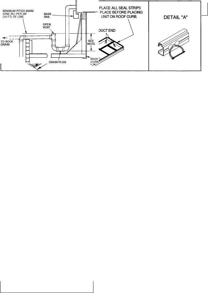
Step 3 Ð Make Field Connection for Condensate Disposal Ð Units must have an external trap added. See Fig. 3. A 3¤4-in. FPT connection is located on the side of the unit. Use a trap at least 100 mm (4 in.) deep, and protect against freeze-up.
If drain line is run to a drain, pitch line away from unit at 25 mm (one in.) per 3 m (10 ft) of run. Do not use a pipe size smaller than the unit connection.
Step 4 Ð Rig and Place Unit Ð Inspect unit for transportation damage. File any claim with transportation agency. Keep unit upright and do not drop. Spreader bars are not required if top crating is left on unit. Rollers may be used to move unit across a roof. Level by using unit frame as a reference. See Tables 1A and 1B and Fig. 4 for additional information. Operating weight is shown in Tables 1A and 1B and Fig. 4.
Lifting holes are provided in base rails as shown in Fig. 4 and 5. Refer to rigging instructions on unit.
NOTES:
1. Dimensions in ( ) is in millimeters.
2.Hood rigging shackles through holes in base rail, as shown in detail ``A''. Holes in base rails are centered around the unit center of gravity. Use wooden top skid when rigging to prevent rigging straps from damaging unit.
3.Weights do not include economizer. See Tables 1A and 1B for economizer weights.
All panels must be in place when rigging.
All panels must be in place when rigging.
POSITIONING Ð Maintain clearance around and above unit to provide proper air ¯ow and service access. See Fig. 5.
Position unit on roof curb so that the following clearances are maintained; 6 mm (1¤4 in.) clearance between roof curb and base rails on each side and front of unit: 29 mm (15¤32 in.) clearance between roof curb and rear of unit (see Fig. 1, section C-C).
Do not install unit in an indoor location. Do not locate unit air inlet near exhaust vents or other sources of contaminated air.
Although unit is weatherproof, guard against water from higher level runoff and overhangs.
After unit is in position, remove polyethylene shipping wrapper and rigging skid.
NOTE: Trap should be deep enough to offset maximum unit static difference. A 100 mm (4 in.) trap is recommended.
Fig. 3 Ð External Trap Condensate Drain
UNIT |
MAX |
|
|
DIMENSIONS |
|
|
|||
WEIGHT |
``A'' |
``B'' |
``C'' |
||||||
50LJQ |
|||||||||
|
lb |
kg |
in. |
mm |
in. |
mm |
in. |
mm |
|
008 |
840 |
381 |
87.38 |
2219 |
40.25 |
1022 |
41.31 |
1050 |
|
012 |
940 |
426 |
87.38 |
2219 |
40.25 |
1022 |
48.31 |
1253 |
|
|
|
|
|
|
|
|
|
|
|
Fig. 4 Ð Rigging Details
3
Table 1A Ð Physical Data (SI)
BASE UNIT 50LJQ |
008 |
|
012 |
NOMINAL CAPACITY (kW) |
23.2 |
|
28.8 |
OPERATING WEIGHT (kg) |
|
|
|
Unit |
381 |
|
426 |
With Economizer |
401 |
|
446 |
Roof Curb |
101 |
|
101 |
COMPRESSOR |
|
Hermetic |
|
Quantity |
2 |
|
2 |
Oil (ml) (each compressor) |
1627 |
|
2071 |
REFRIGERANT TYPE |
|
R-22 |
|
Operating Charge (kg) |
|
|
|
Circuit 1 |
3.7 |
|
4.0 |
Circuit 2 |
3.2 |
|
3.9 |
OUTDOOR FAN |
|
Propeller |
|
Quantity...Diameter (mm) |
1...660 |
|
1...660 |
Nominal L/s |
2900 |
|
3260 |
Motor BkW...r/s |
.25...16.0 |
|
.25...16.0 |
OUTDOOR COIL |
Enhanced Copper Tubes, Aluminum Fins, Acutrol™ Feed Device |
||
Rows...Fins/m |
2...669 |
|
2...669 |
Total Face Area (sq m) |
1.9 |
|
2.3 |
INDOOR FAN |
|
Centrifugal |
|
Size (mm) |
381 x 381 |
|
381 x 381 |
Type Drive |
Belt |
|
Belt |
Nominal L/s |
1200 |
|
1600 |
Motor BkW per NEC* |
1.12 |
|
1.50 |
Maximum Continuous BkW |
1.79 |
|
2.16 |
Motor Frame |
56 |
|
56 |
Fan r/s Range |
10.30-14.70 |
|
11.50-15.00 |
Motor Bearing Type |
Ball |
|
Ball |
Maximum Fan r/s |
26.7 |
|
26.7 |
Motor Pulley Pitch Diameter |
61/86 |
|
86/112 |
A/B (mm) |
|
||
|
|
|
|
Fan Pulley Pitch Diameter (mm) |
140 |
|
178 |
Belt Ð Type...Length (mm) |
A...1219 |
|
A...1295 |
Pulley Center Line Distance (mm) |
425-489 |
|
464-527 |
Fan Shaft Diameter at Pulley (mm) |
25 |
|
25 |
Speed Change per Full Turn of |
.88 |
|
.70 |
Movable Pulley Flange (r/s) |
|
||
|
|
|
|
Movable Pulley Maximum Full |
5 |
|
5 |
Turns from Closed Position |
|
||
|
|
|
|
Factory Setting Ð Full Turns Open |
5 |
|
5 |
Factory Speed Setting (r/s) |
10.3 |
|
11.5 |
INDOOR COIL |
Enhanced Copper Tubes, Aluminum Double Wavy Fins, |
||
Rows...Fins/m |
|
Acutrol Feed Device |
|
3...590 |
|
3...590 |
|
Total Face Area (sq m) |
.74 |
|
.93 |
OUTDOOR-AIR INLET SCREENS |
|
Cleanable |
|
Quantity...Size (mm) |
|
1...508 x 635 x 25 |
|
|
1...406 x 635 x 25 |
||
|
|
||
RETURN-AIR FILTERS |
|
Disposable |
|
Quantity...Size (mm) |
4...406 x 508 x 50 |
|
4...508 x 508 x 50 |
LEGEND
BkW Ð Brake Kilowatt
NEC Ð National Electrical Code (U.S.A. Standard) *Used to determine wire sizing per NEC.
4
Table 1B Ð Physical Data (English)
BASE UNIT 50QJ |
008 |
|
012 |
NOMINAL CAPACITY (tons) |
6.6 |
|
8.2 |
OPERATING WEIGHT (lb) |
|
|
|
Unit |
840 |
|
940 |
With Economizer |
884 |
|
984 |
Roof Curb |
223 |
|
223 |
COMPRESSOR |
|
Hermetic |
|
Quantity |
2 |
|
2 |
Oil (¯uid oz) (each compressor) |
55 |
|
70 |
REFRIGERANT TYPE |
|
R-22 |
|
Operating Charge (lb-oz) |
|
|
|
Circuit 1 |
8-2 |
|
8-14 |
Circuit 2 |
7-0 |
|
8-10 |
OUTDOOR FAN |
|
Propeller |
|
Quantity...Diameter (in.) |
1...26 |
|
1...26 |
Nominal Cfm |
6100 |
|
6900 |
Motor Hp...Rpm |
1¤3...960 |
|
1¤3...960 |
OUTDOOR COIL |
Enhanced Copper Tubes, Aluminum Fins, Acutrol™ Feed Device |
||
Rows...Fins/in. |
2...17 |
|
2...17 |
Total Face Area (sq ft) |
20.5 |
|
25.0 |
INDOOR FAN |
|
Centrifugal |
|
Size (in.) |
15 x 15 |
|
15 x 15 |
Type Drive |
Belt |
|
Belt |
Nominal Cfm |
2600 |
|
3400 |
Horsepower per NEC* |
1.5 |
|
2.0 |
Maximum Continuous Bhp |
2.4 |
|
2.9 |
Motor Frame |
56 |
|
56 |
Fan Rpm Range |
622-882 |
|
692-896 |
Motor Bearing Type |
Ball |
|
Ball |
Maximum Fan Rpm |
1600 |
|
1600 |
Motor Pulley Pitch Diameter |
2.4/3.4 |
|
3.4/4.4 |
A/B (in.) |
|
||
|
|
|
|
Fan Pulley Pitch Diameter (in.) |
5.5 |
|
7.0 |
Belt Ð Type...Length (in.) |
A...48 |
|
A...51 |
Pulley Center Line Distance (in.) |
16.75-19.25 |
|
18.25-20.75 |
Fan Shaft Diameter at Pulley (in.) |
1 |
|
1 |
Speed Change per Full Turn of |
52 |
|
42 |
Movable Pulley Flange (rpm) |
|
||
|
|
|
|
Movable Pulley Maximum Full |
5 |
|
5 |
Turns from Closed Position |
|
||
|
|
|
|
Factory Setting Ð Full Turns Open |
5 |
|
5 |
Factory Speed Setting (Rpm) |
620 |
|
690 |
INDOOR COIL |
Enhanced Copper Tubes, Aluminum Double Wavy Fins, |
||
Rows...Fins/in. |
|
Acutrol Feed Device |
|
3...15 |
|
3...15 |
|
Total Face Area (sq ft) |
8.0 |
|
10.0 |
OUTDOOR-AIR INLET SCREENS |
|
Cleanable |
|
Quantity...Size (in.) |
|
1...20 x 25 x 1 |
|
|
1...16 x 25 x 1 |
||
|
|
||
RETURN-AIR FILTERS |
|
Disposable |
|
Quantity...Size (in.) |
4...16 x 20 x 2 |
|
4...20 x 20 x 2 |
LEGEND
Bhp Ð Brake Horsepower
NEC Ð National Electrical Code (U.S.A. Standard) *Used to determine wire sizing per NEC.
5
UNIT |
STD. UNIT |
ECONOMIZER |
CORNER |
CORNER |
CORNER |
CORNER |
``H'' |
``J'' |
``K'' |
|
||||||||||
WEIGHT |
WEIGHT |
WEIGHT ``A'' |
WEIGHT ``B'' |
WEIGHT ``C'' |
WEIGHT ``D'' |
|
||||||||||||||
50LJQ |
|
|
|
|
|
|
|
|||||||||||||
Lb |
Kg |
Lb |
Kg |
Lb |
Kg |
Lb |
Kg |
Lb |
|
Kg |
Lb |
Kg |
Ft-in. |
mm |
Ft-in. |
mm |
Ft-in. |
|
mm |
|
|
|
|
||||||||||||||||||
008 |
840 |
381 |
44 |
20 |
182 |
83 |
156 |
71 |
231 |
|
105 |
271 |
123 |
2-07¤8 |
632 |
3-55¤16 |
1050 |
2-911¤16 |
|
856 |
012 |
940 |
426 |
44 |
20 |
204 |
93 |
174 |
79 |
259 |
|
117 |
303 |
137 |
1-27¤8 |
378 |
4-15¤16 |
1253 |
3-03¤8 |
|
924 |
|
|
|
|
|
|
|
|
|
NOTES: |
|
|
|
|
|
|
|
|
|
||
|
|
|
|
|
|
|
|
|
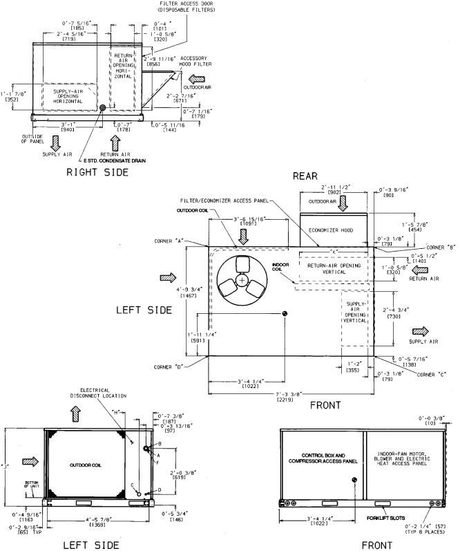
1. |
Dimensions in [ ] are in millimeters. |
|
|
|
|
||||||
2.  Center of gravity.
-
Fig. 5 Ð Base Unit Dimensions
6
Step 5 Ð Make Electrical Connections
Unit cabinet must have uninterrupted, unbroken electrical ground to minimize the possibility of personal injury if an electrical fault should occur. This ground may consist of electrical wire connected to unit ground lug in control compartment, or conduit approved for electrical ground when installed in accordance with U.S.A. National Electrical Code (Ref: ANSI/NFPA 70-1987) or equivalent local electrical codes. Failure to follow this warning could result in the installer being liable for personal injury of others.
FIELD POWER SUPPLY Ð Pigtails are provided for ®eld wire connections. Use factory-supplied splices or copper/ aluminum connector.
When installing units, provide a disconnect per local codes. All ®eld wiring must comply with local requirements.
Install conduit through side panel openings. For units without electric heat, install conduit between disconnect and control box. Install power lines to terminal connections as shown in Fig. 6. For units with electric resistance heat, refer to Table 2 to determine appropriate power wiring ®gure (Fig.7-13) and route lines as indicated in appropriate ®gure.
Voltage to compressor terminals during operation must be within voltage range indicated on unit nameplate (also see Table 2). On 3-phase units, voltages between phases must be balanced within 2% and the current within 10%. Use the formula shown in Table 2, Note 3 to determine the % voltage imbalance. Operation on improper line voltage or excessive phase imbalance constitutes abuse and may cause damage to electrical components. Such operation would invalidate any applicable Carrier warranty.
When electric heat is installed, remove knockouts for appropriate size conduit from unit block-off panel and single point box. Install conduit (rigid or electro-metallic tubing) through conduit drip boot as shown in Fig. 14. Drip boot eliminates the need for water tight conduit ®ttings at the single point box. Refer to Fig. 15 for component locations.
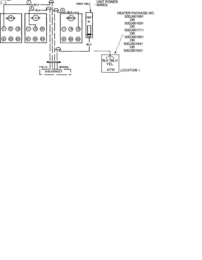
LEGEND
C Ð Contactor
IFC Ð Indoor-Fan Contactor
TB Ð Terminal Block
Field Wiring
Factory Wiring
Splice Connection (Factory Supplied)
Fig. 6 Ð Power Wiring Connections
LEGEND |
FOR FIG. 7-13 |
|
EQUIP |
Ð |
Equipment |
FU |
Ð |
Fuse |
GND |
Ð |
Ground |
HTR |
Ð |
Heater |
TB |
Ð |
Terminal Block |
Fig. 7 Ð Electric Heater Power Wiring Connections Ð 50LJQ, 220-3-50 and 400-3-50; Single Point Kit 50DJ902021 and 50DJ902071
7
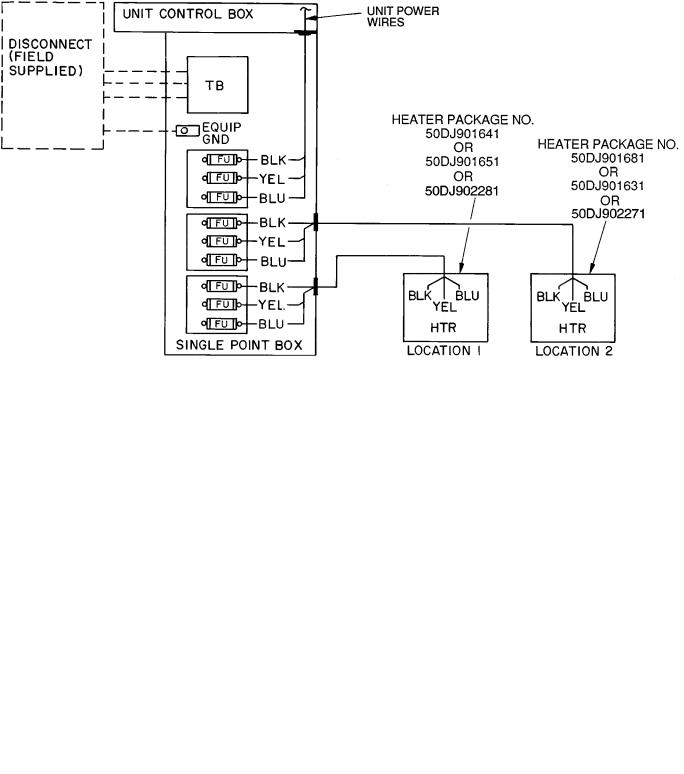
Fig. 8 Ð Electric Heater Power Wiring Connections Ð 50LJQ, 400-3-50; Single Point Kit 50DJ902041 and 50DJ902101
Fig. 9 Ð Electric Heater Power Wiring Connections Ð 50LJQ, 400-3-50; Single Point Kit 50DJ902061 and 50DJ902121
8
 Loading...