


INSTRUCTION MANUAL
ENGLISH

 Introduction
Thank you for purchasing the Canon Communication Camera VC-C50i/VC-C50iR. Please read this Instruction Manual carefully to ensure that you use the Product correctly and safely. Read the “a Safe Use of Equipment” section first and observe these instructions when you use the Product.
Features of the VC-C50i/VC-C50iR Communication Camera
■Genuine Canon 26× optical zoom and 12× digital zoom for highmagnification imaging
■Capable of shooting at low light levels down to 1 lux
■Built-in infrared light allows shooting even at 0 lux (Night mode)
■High-speed high-precision camera head movement
■Noise reduction circuitry for crystal clear images
2

Introduction
Notice
This product uses a microcomputer. External radio frequency energy, may cause picture interference, avoid using this product in such a location.
Exclusion of Liability
If the Product is connected to a recording device (for example a VCR), Canon Inc. accepts no responsibility whatsoever for any financial losses that may be incurred as a result of the loss of recorded information or images, regardless of the internal or external cause of the loss.
Copyright Information |
|
|
Video or still images recorded using your VC-C50i/VC-C50iR cannot be used in |
ENGLISH |
|
ways that infringe copyright laws or without the consent of the owner, unless |
||
|
||
intended for personal use only. |
|
|
Note |
|
|
The contents of this Manual are subject to change without notice. |
|
CANON and the CANON logo are registered trademarks of Canon Inc. Other names of products and companies mentioned in this Manual are trademarks or registered trademarks of the respective companies.
© Copyright 2003 CANON INC.
ALL RIGHTS RESERVED
3

 a Safe Use of Equipment
aAn exclamation point, within a triangle, is intended to alert the user to the presence of important operating and maintenance (servicing) instructions in the literature
accompanying the equipment.
 a Important Warnings
a CAUTION:
TO REDUCE THE RISK OF ELECTRIC SHOCK, DO NOT REMOVE COVERS. NO USER-SERVICEABLE PARTS INSIDE. REFER SERVICING TO QUALIFIED SERVICE PERSONNEL.
The serial number of this equipment may be found on the back of the camera head. No others have the same serial number as yours.
You should record the number and other vital information here and retain this book as a permanent record of your purchase to aid identification in case of theft.
Date of Purchase Dealer Purchased from Dealer Address
Dealer Phone No.
Model No. VC-C50i or VC-C50iR
Serial No.
For Users in the UK (PA-V16)
When replacing the fuse only a correctly rated approved type should be used and be sure to re-fit the fuse cover.
The AC adapter can be connected to the VC-C50i/VC-C50iR from a standard AC power outlet. Please check your instruction manual to make sure that your VC-C50i/VC-C50iR is compatible with this adapter.
–The socket-outlet should be installed near the equipment and should be easily accessible.
–Unplug the apparatus from the wall outlet before cleaning or maintaining.
4

a Safe Use of Equipment
 a Important Operational Instructions
a WARNING:
TO REDUCE THE RISK OF ELECTRIC SHOCK, DO NOT EXPOSE THIS EQUIPMENT TO RAIN OR MOISTURE.
a CAUTION:
TO REDUCE THE RISK OF ELECTRIC SHOCK AND TO REDUCE ANNOYING INTERFERENCE, USE THE RECOMMENDED ACCESSORIES ONLY.
FDA regulation |
ENGLISH |
|
This equipment has not been evaluated by the Food and Drug Administration |
||
|
||
(FDA) for use as a medical device. When incorporated into a system with |
|
|
medical applications, FDA regulations may apply. Consult your legal advisor to |
|
|
determine whether FDA regulations apply. |
|
5

a Safe Use of Equipment
FCC NOTICE
COMMUNICATION CAMERA, Model: PT-50iN/PT-50iNR/PT-50iP/PT-50iPR This device complies with Part 15 of the FCC Rules. Operation is subject to the following two conditions: (1) This device may not cause harmful interference, and (2) this device must accept any interference received, including interference that may cause undesired operation.
Note: This equipment has been tested and found to comply with the limits for a Class B digital device, pursuant to Part 15 of the FCC Rules. These limits are designed to provide reasonable protection against harmful interference in a residential installation. This equipment generates, uses and can radiate radio frequency energy and, if not installed and used in accordance with the instructions, may cause harmful interference to radio communications. However, there is no guarantee that interference will not occur in a particular installation. If this equipment does cause harmful interference to radio or television reception, which can be determined by turning the equipment off and on, the user is encouraged to try to correct the interference by one or more of the following measures:
-Reorient or relocate the receiving antenna.
-Increase the separation between the equipment and receiver.
-Connect the equipment into an outlet on a circuit different from that to which the receiver is connected.
-Consult the dealer or an experienced radio/TV technician for help.
Use of shielded cable is required to comply with class B limits in Subpart B of Part 15 of FCC Rules.
Do not make any changes or modifications to the equipment unless otherwise specified in the manual. If such changes or modifications should be made, you could be required to stop operation of the equipment.
Canon U.S.A. Inc.
One Canon Plaza, Lake Success, NY 11042, U.S.A. Tel No. (516) 328-5600
IC NOTICE
This product does not exceed the Class B limits for radio noise emissions from digital apparatus as set out in the Interference-causing equipment standard entitled ‘Digital Apparatus’, ICES-003 of the Industry Canada.
6

a Safe Use of Equipment
 a IMPORTANT SAFETY INSTRUCTIONS
In these safety instructions, the word
“equipment” refers to the Canon communication camera VC-C50i/VC-C50iR and all its accessories.
1.Read Instructions - All the safety and operating instructions should be read before the equipment is operated.
2.Retain Instructions - The safety and operating instruction should be retained for future reference.
3.Heed Warnings - All warnings on the equipment and in the operating instructions should be adhered to.
4.Follow Instructions - All operating and maintenance instructions should be followed.
5.Cleaning - Unplug this equipment from the wall outlet before cleaning.
Wipe the equipment with a clean soft cloth. If necessary, put a cloth in diluted neutral detergent and wring it well before wiping the equipment with it.
Finally, clean the equipment with a clean dry cloth. Do not use benzene, thinner or other volatile liquids or pesticides as they may damage the product’s finish. When using chemicallytreated cleaning cloths, observe those precautions accordingly.
6.Accessories - Do not use accessories not recommended in this manual as they may be hazardous. Always use specified connection cables. Connect devices correctly.
7.Water and Moisture - Hazard of electric shock - Do not use the equipment near water or in rainy/moist situations. Do not put a heater near this equipment.
8.Placing or Moving - Do not place on an
unstable cart, stand, tripod, bracket or table. The equipment may fall, causing
serious injury to a child or adult, and serious damage to the equipment. An equipment and cart combination should be moved with care. Quick stops, excessive force, and uneven surfaces may cause the equipment and cart combination to overturn.
9.Power Sources - The PA-V16 AC adapter should be operated only from the type of power source indicated on the marking label. If you are not sure of the type of power supply to your home, consult your equipment dealer or local power company.
10.Polarization - The PA-V16 AC adapter is equipped with a polarized 2-prong plug (a plug having one blade wider than the other).
The 2-prong polarized plug will fit into the power outlet only one way. This is a safety feature. If you are unable to insert the plug fully into the outlet, try reversing the plug. If the plug still fails to fit, contact your electrician to replace your obsolete outlet. Do not defeat the safety purpose of the polarized plug.
11.Power Cord Protection - Power cords should be routed so that they are not likely to be walked on or pinched by items placed upon or against them. Pay particular attention to plugs and the point from which the cords exit the equipment.
12.Outdoor Antenna Grounding - If an outside antenna is connected to the equipment, be sure the antenna is grounded so as to provide some protection against voltage surges and built-up static charges. Section 810 of the National Electrical Code, ANSI/
NFPA No.70-1984, provides information with respect to proper grounding of the mast and supporting structure, grounding of the lead-in wire to an antenna discharge unit, size of grounding conductors, location of
ENGLISH |
7
a Safe Use of Equipment
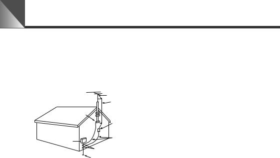
antenna discharge unit, connection to grounding electrodes, and requirements for the grounding electrode. See figure
1.
fig-1
EXAMPLE OF ANTENNA GROUNDING AS
PER NATIONAL ELECTRICAL CODE
|
ANTENNA LEAD |
|
IN WIRE |
GROUNDING |
ANTENNA |
DISCHARGE |
|
CLAMP |
UNIT (NEC |
|
SECTION 810-20) |
ELECTRIC |
GROUNDING |
CONDUCTORS |
|
SERVICE |
(NEC SECTION |
EQUIPMENT |
810-21) |
|
GROUNDING CLAMPS |
parts that could result in a fire or electric shock. Be careful not to spill liquid of any kind onto the equipment.
17.Servicing - Do not attempt to service this equipment yourself as opening or removing covers may expose you to dangerous voltage or other hazards.
Refer all servicing to qualified personnel.
18.Damage Requiring Service -
Disconnect this equipment from the wall outlet and all power sources including batteries, and refer servicing to qualified service personnel under the following conditions.
a.When the power-supply cord or plug is damaged.
POWER SERVICE GROUNDING ELECTRODE SYSTEM
NEC — NATIONAL ELECTRIC CODE (NEC ART 250. PART H)
13.Lightning - For added protection of this equipment during a lightning storm, or when it is left unattended and unused for long periods of time, disconnect it from the wall outlet and disconnect the antenna. This will prevent damage to the equipment due to lightning and power-line surges.
14.Power Lines - An outside antenna system should not be located in the vicinity of overhead power lines or other electric light or power circuits, or where it can fall into such power lines or circuits. When installing an outside antenna system, extreme care should be taken to keep from touching such power lines or circuits as contact with them might be fatal.
15.Overloading - Do not overload wall outlets and extension cords as this can result in a risk of fire or electric shock.
16.Object and Liquid Entry - Never push objects of any kind into this equipment through openings as they may touch dangerous voltage points or short out
b.If any liquid has been spilled onto, or objects have fallen into, the equipment.
c.If the equipment has been exposed to rain or water.
d.If the equipment does not operate normally even if you follow the operating instructions. Adjust only those controls that are covered by the operation instructions. Improper adjustment of other controls may result in damage and will often require extensive work by a qualified technician to restore the equipment to its normal operation.
e.If the equipment has been dropped or the cabinet has been damaged.
f.When the equipment exhibits a distinct change in performance. This indicates a need for service.
19.Replacement Parts - When replacement parts are required, be sure the service technician has used replacement parts that are specified by Canon or that have the same characteristics as the original part. Unauthorized substitutions may result in fire, electric shock or other hazards.
8

a Safe Use of Equipment
20.Safety Check - Upon completion of any service or repairs to this equipment, ask the service technician to perform safety checks to determine that the equipment is in safe operating order.
21.Do not install the equipment in the following locations as this can cause a fire or electric shock:
-Hot locations
-Close to a fire
-Very humid or dusty locations
-Locations exposed to direct sunlight
-Locations exposed to salt spray
-Close to flammable solvents (alcohol, thinners, etc.)
22.When any of the following occurs, immediately switch OFF the equipment, unplug it from the main power supply and contact your nearest Canon supplier. Do not continue to use the equipment as this can cause a fire or electric shock.
-The equipment emits any smoke, heat, abnormal noise, or unusual odor.
-A metal object falls into the equipment.
-The equipment is damaged in some way.
23.Please observe the following when using the equipment. Failure to do so can result in a fire or electric shock.
-Do not use flammable sprays near the equipment.
-Do not subject the equipment to strong impacts.
24.Please observe the following when handling the batteries. Failure to do so can result in the batteries bursting or emitting heat, sparks or corrosive fluid.
-Do not throw the batteries into a fire, and do not heat, short-circuit or attempt to disassemble the batteries.
-Do not attempt to recharge the batteries.
-Do not use batteries other than those specified for use with the equipment.
25.Please observe the following when handling the batteries. Failure to do so may result in the batteries bursting or emitting heat, sparks or corrosive fluid.
-When the batteries are used up, or when the equipment will not be used for an extended period, remove the batteries.
-When replacing the batteries, always replace both batteries, and do not use different types of batteries together.
-Ensure that the + and – terminals are correctly positioned when you load the batteries.
-If any soiling or leakage of the internal battery fluid occurs, thoroughly clean the soiling or leaked fluid with water.
ENGLISH |
9
a Safe Use of Equipment
 Maintenance
Cleaning the Equipment
1.Unplug the AC adapter from the wall outlet.
2.Carefully wipe the equipment with a soft cloth that has been moistened with water or a mild detergent.
aWARNING
Do not use flammable solvents such as alcohol, benzene or thinners.
The use of such substances can cause a fire or electric shock.
3. Wipe with a dry cloth.
4. When you have finished, plug the AC adapter back in to the wall outlet.
Cleaning the Lens
Use a commercially available lens cleaner to remove any soiling from the lens.
■The auto-focus may not function correctly if the surface of the lens is dirty.
■Scratches on the surface of the lens will cause image defects.
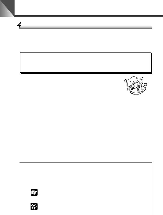
Icons Used in This Instruction Manual
aWARNING Represents instructions that, if ignored, could result in death or serious personal injury caused by incorrect operation of equipment. Instructions indicated by this icon must be observed for safe operation.
Indicates important information that must be observed or actions
that are prohibited during an operation. These notes must be
NOTE
read to prevent possible faults or damage to the equipment.
Indicates supplementary information or a reference to an
operation. Users are advised to read these memos.
MEMO
10
CONTENTS |
|
|
|
a Safe Use of Equipment .......................................................................................... |
4 |
|
|
a Important Warnings ................................................................................... |
4 |
|
|
a Important Operational Instructions .......................................................... |
5 |
|
|
a IMPORTANT SAFETY INSTRUCTIONS ..................................................... |
7 |
|
|
Maintenance .................................................................................................. |
10 |
|
|
Icons Used in This Instruction Manual............................................................. |
10 |
|
|
Before You Use the Product .................................................................................... |
12 |
|
|
Checking the Camera and Its Accessories ................................................. |
12 |
|
|
Nomenclature ................................................................................................ |
12 |
|
|
Installing the Product ................................................................................... |
13 |
|
|
Connecting the Components ....................................................................... |
14 |
|
|
Turning the Power ON and OFF ................................................................... |
18 |
|
|
LED Displays and the Camera Status ....................................................................... |
18 |
ENGLISH |
|
Controlling the Camera from the Wireless Controller |
19 |
||
|
|||
Nomenclature ................................................................................................ |
19 |
|
|
Loading the Batteries into the Wireless Controller ................................... |
20 |
|
|
Operable Range of the Wireless Controller ............................................................... |
20 |
|
|
Changing the Camera Head Angle (pan/tilt/home position) ..................... |
21 |
|
|
Range of Camera Head Movement ........................................................................... |
21 |
|
|
Zooming In/Out (TELE/WIDE) ....................................................................... |
22 |
|
|
Focusing (FOCUS) ........................................................................................ |
23 |
|
|
Adjusting the Brightness (BRIGHT) ............................................................ |
24 |
|
|
Storing a Preset Camera Position (PRESET) ............................................. |
25 |
|
|
Switching the Camera ON and OFF ............................................................. |
26 |
|
Camera Settings ....................................................................................................... |
27 |
Buttons Used to Specify the Settings ......................................................... |
27 |
Setting Menu Description .......................................................................................... |
27 |
Setting the Clock ........................................................................................... |
28 |
Entering Characters ...................................................................................... |
29 |
Selecting Display/Hide Clock and Text ....................................................... |
29 |
Setting the Camera Head Movement Speed and Pan Operation .................... |
30 |
Setting the Range of Camera Head Movement .......................................... |
31 |
Setting the AE ................................................................................................ |
32 |
Night Mode Settings .................................................................................... |
33 |
VC-C4 Mode Setting Menu .......................................................................... |
33 |
RS-232C Settings .......................................................................................... |
34 |
ID Mode ...................................................................................................................... |
35 |
Setting the ID Number .................................................................................. |
35 |
Selecting the Camera to be Controlled ....................................................... |
36 |
Cancelling ID Mode ....................................................................................... |
37 |
Troubleshooting ........................................................................................................ |
38 |
Factory Default Settings ........................................................................................... |
40 |
Specifications ............................................................................................................ |
41 |
11
 Before You Use the Product
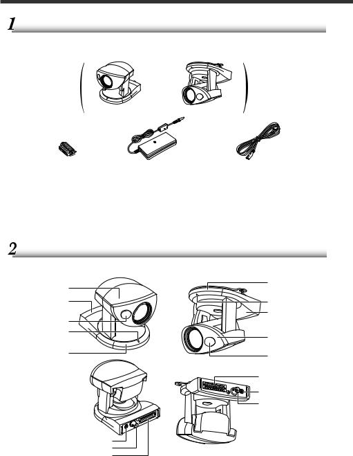
 Checking the Camera and Its Accessories
Before you install the Product, check that all the items shown below are included in your product package. If any of these items is missing, contact your Canon dealer.
or
VC-C50i camera |
VC-C50iR camera |
Multiconnector |
AC adapter PA-V16 |
AC cable |
||
Plug |
(NTSC model only) |
(NTSC model only) |
||
● Instruction Manual |
|
|
|
|
|
■ Optional Product |
|||
● Warranty Card (NTSC model only) |
||||
● Wireless Controller WL-V5 (→ P.19) |
||||
|
|
|||
|
|
● Wide-angle Converter WL-37 (→ P.14) |
||
|
|
Cannot be used on the VC-C50iR. |
||
|
|
|
|
|
 Nomenclature
|
VC-C50i |
VC-C50iR |
Camera head |
(Front) |
Wireless controller |
|
sensor (→ P.20) |
|
(→ P.21) |
|
|
|
LED (→ P.18) |
|
Base (→ P.13) |
|
|
Infrared light window |
|
Base (→ P.13) |
|
|
|
(→ P.33) |
|
|
LED (→ P.18) |
|
Camera head |
|
|
|
Wireless controller |
|
(→ P.21) |
|
Infrared light |
|
sensor (→ P.20) |
(Rear) |
|
|
window (→ P.33) |
|
|
|
Multiconnector |
|
|
(→ P.14) |
|
|
DC IN 13V terminal |
|
|
(→ P.14) |
VIDEO OUT terminal (→ P.14)
DC IN 13V terminal (→ P.14) |
VIDEO OUT terminal (→ P.14) |
Multiconnector (→ P.14) |
* The screw mount for a tripod is located in the center of the underside of the camera.
12
|
Before You Use the Product |
|
|
|
|
|
|
|
|
|
|
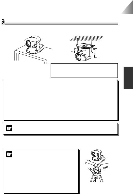
Installing the Product |
|
|
|
VC-C50i Installation |
VC-C50iR Installation |
|
|
Install in a flat and stable location. |
Firmly tighten the 2 screws (not supplied). |
|
|
Mounting plate
VC-C50iR
Screw
Screw
(Installation)
•Distance between tapped holes: 114 mm (4.49 in.)
•Tapped hole diameter: 6 mm (0.24 in.)
•Mounting plate thickness: 1 mm (0.04 in.)
aWARNING
Install the camera securely.
●When installing the camera on the ceiling, contact your Canon dealer.
●When installing the camera on the ceiling, check that the ceiling is strong enough to bear the weight of the camera including the installation bracket. Installation in a weak location could result in the camera falling and causing serious injury.
●At least once a year, check for looseness in the camera installation mount. (If the optional wide-angle converter is used, check the converter mount also.)
*The Wide-angle Converter WL-37 cannot be used on the VC-C50iR.
The permissible camera installation angles are ±20° from the horizontal. (±15°
when the optional wide-angle converter is used.)
NOTE
ENGLISH |
Using a Tripod
The screw mount for a tripod is located in the center of the underside of the camera.
● Do not overtighten the mounting screw.
If excessive force is used to tighten the
NOTE
mounting screw, camera head movement may be impeded, or other malfunctions may result.
●Always use a tripod mounting screw that is less than 6.0 mm (0.24 in.) in length. The use of screws 6.0 mm (0.24 in.) long or longer could damage the camera. Also, the tripod seat used should be at least 30 mm (1.18 in.) in diameter.
30 mm |
Less than |
(1.18 in.) |
6.0 mm |
or wider |
(0.24 in.) |
Mounting
 screw
screw
13
 Loading...