


Canon MP800, MP530, iP5200, MP830, IP4200 User Manual
...Premium
Continuous
Ink Supply
Systems.
Instruction Manual
For Canon Printers
IP4200, IP5200
MP800 & MP830
MP500, MP530
157 Union Road, Ascot Vale, Victoria 3032 | Phone: (+613) 9005 5555
2
|
Installation Manual |
|
|
IP4200, IP5200, MP800, MP830 – 100ml Series |
|
|
Version 6-2009 |
|
Installation Manual .................................................................................................................................................................................. |
3 |
|
1) |
Printer pre-check. ........................................................................................................................................................................... |
5 |
2) |
Preparing your new CISS for installation....................................................................................................................................... |
7 |
3) |
Attaching Cartridge Chips – un chipped CISS unit only................................................................................................................ |
8 |
4) |
Preparing your ink reservoirs ....................................................................................................................................................... |
10 |
5) |
Inserting the silicone nozzle seals. ............................................................................................................................................... |
11 |
6) |
Inserting the cartridges ................................................................................................................................................................. |
12 |
7) |
Tube set up (IP Series Only) ........................................................................................................................................................ |
13 |
8) |
Tube set up (MP800 and MP830 only) ........................................................................................................................................ |
15 |
9) |
Tube set up (MP500 ONLY)........................................................................................................................................................ |
17 |
10) |
Tube set up (MP530 only)............................................................................................................................................................ |
19 |
11) |
Final touches (all models) ............................................................................................................................................................ |
22 |
12) |
Refilling your CISS ...................................................................................................................................................................... |
23 |
13) |
Priming......................................................................................................................................................................................... |
24 |
14) |
Cartridge chip disable - Low ink. ................................................................................................................................................. |
26 |
15) |
Trouble Shooting.......................................................................................................................................................................... |
28 |
17) |
Canon Error Messages.................................................................................................................................................................. |
31 |
18) |
Warranty....................................................................................................................................................................................... |
34 |
19) |
Warning........................................................................................................................................................................................ |
34 |
3
4

Instruction Manual
Canon Printers
IP4200, IP5200, MP800, MP830 – 100ml Series
Congratulations on your purchase of a rihac tm Continuous Ink Supply System (CISS). Before using the system please read this manual carefully. It will help you install the system correctly and ensure trouble free printing.
Great care is taken to prepare your CISS for trouble free installation. Your CISS has been primed (Australian customers only) and should be ready for immediate installation into your printer.
Please be aware that some of the pictures in this manual may not represent the printer you are working with. Throughout the installation process please feel free to contact us or refer to our website, www.rihac.com.au for any troubleshooting and frequently asked questions. If you are installing this unit into an MP500 or MP530 you will require an additional instruction sheet with specific details for those printers
1)Printer pre-check.
Before opening your CISS, please perform the following print tests to ensure your printer heads are in good condition.
a)Perform a printer head clean.
For Windows XP users, this is done by accessing your printer properties through the start menu on the bottom left of your screen and choosing the control panel. Select the printers and faxes option and locate your printer. Right click your mouse button on the printer icon and choose Properties from the menu, then select the Maintenance tab. Click on the cleaning icon which will be similar to the one pictured below. Choose to perform a head clean on All Colours and then execute the clean.
5
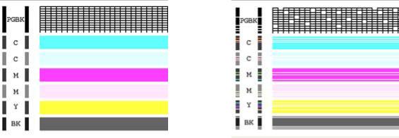
b)After performing a head clean you must then perform Print Check Pattern. The computer will automatically ask you this, however if it does not, simply choose to perform a ‘Nozzle Check’ on the printer maintenance screen.
Your printer will print either of the following;
A |
or |
B |
If your printer has produced a perfect result (A), please attach a copy of the nozzle check to your purchase receipt as this will validate your warranty. You can now start to install your CISS.
If your printer has printed with missing lines or uneven colouring (B) please repeat steps 1.a and b. If your second print is similar to the first, you more then likely have damaged printer heads and you will need them replaced before successfully installing a CISS.
6
2)Preparing your new CISS for installation
Please ensure the following are present with your CISS. |
|
|
(1) |
Air filters x5 |
6 |
|
1 |
|
(2) |
Silicone nozzle seal x 5 |
|
(3) Cable ties (spare) |
5 |
2 |
3 |
|
|
|
(4)Double sided tape tabs (spare)
(5) Syringe and filling needle |
4 |
|
(6)Spare elbow joints and connections
(7)Single spacer clips (for use on MP500/530 only)
b)Remove your CISS from the box and check the there are no leakages or cracks and that the silicone tubing is not damaged.
c)Inspect the silicone tubing for air pockets.
If you have an excessive amount (5cm or more) of air in the tubing,  you will need to prime the unit.
Please refer to page 24 of this installation manual.
This will prevent any problems with your print quality further down the track.
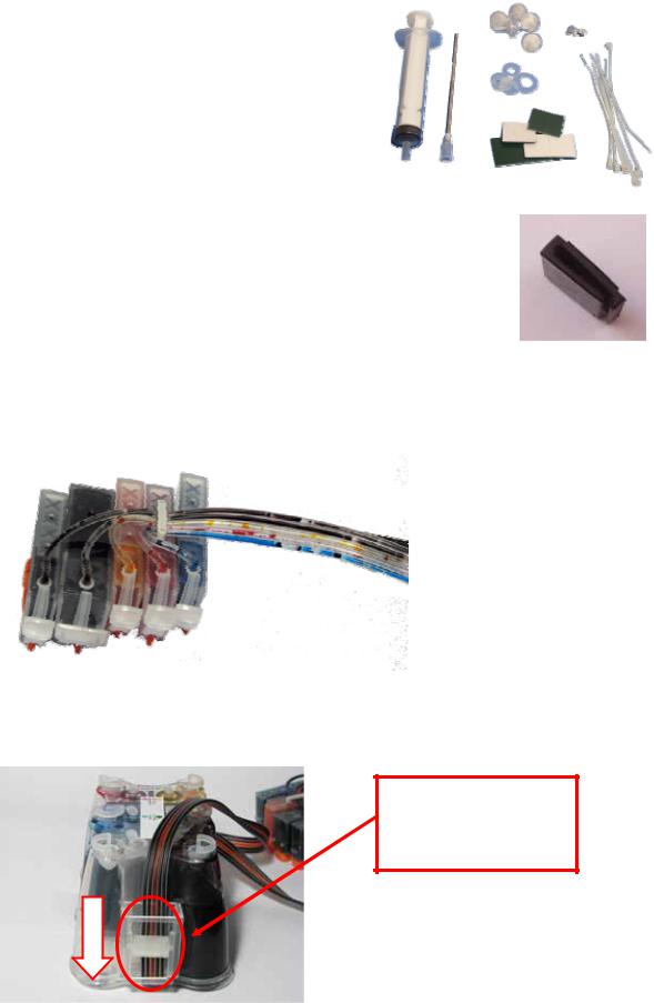
d)Close the tube clamp located on the side of the CISS by rolling the roller down. This will squeeze the silicone tubing which will prevent ink flow.
Engage the tube clamp by rolling the roller down
If you do not close this valve, ink will flow back into the reservoir from your cartridges.
7

3)Attaching Cartridge Chips – un chipped CISS unit only
If you have purchased a pre chipped system please proceed to section 4) on page 10
Your original cartridge chips must be transferred onto the CISS cartridges. Please follow the following steps carefully
a)Turn on your printer and open the cover. The cartridge holder will move to the cartridge change position. Remove power cable from the back of your printer. Remove the cartridges from the printer.
b)Using a Stanley knife or sharp blade remove the two plastic lugs which hold the chip in place. The chips are colour specific so ensure you do not mix them up as they will not work if they are attached incorrectly
c)Gently lift the chip from the cartridge. Never pry off the chip particularly from the top of the chip as you may damage the sensitive electronics on the rear of the chip.
X
8
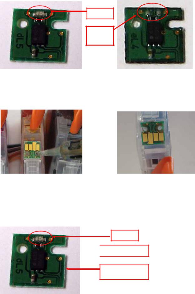
d)Examine the rear of the chip to ensure the LED has not been damaged or cut off.
LED
Missing
LED
undamaged cartridge chip |
damaged cartridge chip |
e)Place the chip onto the corresponding coloured CISS cartridge, ensuring that the small plastic lugs are inserting into the chip holes. Use a soldering iron gently melt the plastic lugs to hold the chip in place.
f)Repeat stepsb) & e) for each of the cartridges on your CISS
Alternatively you can fit the cartridge chips using thin double sided tape although the preferred method is with a soldering iron.
If attaching the chip with double sided tape, please cut the tape and attach it to the rear of the chip as pictured below. DO NOT COVER ATTACHMENT HOLES OR LED.
LED


 Attachment holes
Thin double sided tape
rear of cartridge chip pictured
9

4)Preparing your ink reservoirs
a)Carefully remove the small travel plugs on the CISS, leaving the filler plug in place.
Travel
Plug
Filler
Plug
b)Using the syringe, remove any excess ink from the inner air balance chamber. The chamber does not have to be completely empty for the CISS to function correctly. Removing excess ink simply helps reduces the air pressure drawing back from the cartridges and can assist in preventing air to develop in the ink feeder tubes. The excess ink can be discarded or replaced into the reservoir via the filler plug. Please refer to refilling instruction page 22 .
Air
Balance
Chamber
Never have the filler plug removed at the same time as the travel plug. The air balance chamber has a hole in the base linking it to the main ink reservoir. Having both plugs removed at the same time will re-fill the air balance chamber with ink.
Air
Balance
Chamber
(shown in blue)
10
THE FOLLOWING STEPS ARE VERY IMPORTANT FOR ALL CANON PRINTERS.
5)Inserting the silicone nozzle seals.
a)Remove the printer head from your printer by lifting the print head lock arm. The print head will then lift out
b)Remove the 5 silicone seals from your kit. During manufacture 2 seals may stick together giving the appearance of a single seal.
c)Ensure each seal is clean by placing each seal onto the small pieces of double sided tape provided. Please ensure both sides of the seal are cleaned. Use the tweezers provided to remove each seal from the tape ensuring no dust, dirt or oils are passed onto it from your hands.
d)Carefully place each silicone nozzle seal into position around each of the printer heads as shown.
11
 Loading...