


 Loading...
CANON Digital Galvano Scanner System
GM-1000 Series
GC-201
Users Manual
Rev. 1.20
Be sure to read this guide before using the product.
Keep this guide carefully for future use.

For Safe and Correct Use
To prevent injury to the user or damage to property, this guide gives information for the safe and correct use of this product.
Before installation, operation, maintenance, or inspection, be sure to read this guide.
Markings
This guide uses the following markings:
 Warning
This indicates the possibility of death or serious injury by a fire or electric shock.
 Caution
This indicates the possibility of injury or damage to property.

 Warning
Do not use the product in an atmosphere of inflammable or explosive gas or vapor.Use the product at the specified voltage.
Connect the power supply line correctly.
Do not install, operate, maintain, or inspect the product with wet hands.Do not disassemble or alter this product.
Do not drop or cause impact to the product.

 Caution
Before installation, operation, maintenance, or inspection, thoroughly check that the device is safe.When connecting a connector, check the pin numbers with the power off.
When connecting oscilloscope probes to the test pins, be careful not to apply tension to them.Since this product is a precision device, use it under the specified environmental conditions.
Do not store or transport this product in a place exposed to direct sunlight, moisture, dust, or temperature of 60ºC or higher.
CANON Digital Galvano Scanner System GM-1000 Series
Users Manual 1.20
2
Contents |
|
1. Product Outline............................................................................................................................. |
5 |
1.1. Features ............................................................................................................................................ |
5 |
1.2. Configuration..................................................................................................................................... |
5 |
2. Specifications................................................................................................................................ |
6 |
2.1. Galvano Motor (GM-1010, GM-1015, and GM-1020)........................................................................ |
6 |
2.2. Controller (GC-201)........................................................................................................................... |
7 |
2.3. Dimensions ....................................................................................................................................... |
8 |
2.4. Power Supply .................................................................................................................................. |
11 |
2.5. Connections .................................................................................................................................... |
11 |
2.6. Connector and Pin Assignment....................................................................................................... |
13 |
2.7. Optional Cables............................................................................................................................... |
17 |
2.8. Control Specifications...................................................................................................................... |
19 |
2.8.1. Number of Encoder Pulses.................................................................................................... |
21 |
2.8.2. RS-232C command input .................................................................................................. |
22 |
2.8.3. High-speed serial communication.................................................................................... |
26 |
2.8.3.1. Origin Offset ....................................................................................................................... |
32 |
2.8.3.2. High-speed serial communication motor drive timing......................................................... |
33 |
2.8.4. Status (High-speed Serial Communication STS).......................................................... |
34 |
2.8.5. RS-232C Communication Command Input and High-Speed Communication |
|
Switching .......................................................................................................................................... |
37 |
2.9. Heat Radiation and Installation........................................................................................................ |
38 |
3. Software .......................................................................................................................................... |
39 |
3.1. Supported PC Environment............................................................................................................. |
39 |
3.2. Installation CD................................................................................................................................. |
39 |
3.3. Control Software Installation ........................................................................................................... |
40 |
3.4. Software Start Up ............................................................................................................................ |
43 |
3.5. Control Screen ................................................................................................................................ |
45 |
4. Operating Procedure............................................................................................................... |
47 |
4.1. Controller Start Up........................................................................................................................... |
47 |
4.2. Step Movement ............................................................................................................................... |
49 |
4.2.1. Step Movement Responce Time Measurement............................................................ |
51 |
4.2.1.1. Measurement Data Display Zoom Method ......................................................................... |
54 |
4.2.1.2. Reference Data Comparison Method ................................................................................. |
56 |
4.3. Raster Scan .................................................................................................................................... |
59 |
4.4. Position Command Input by High-speed Serial Communication ..................................................... |
61 |
CANON Digital Galvano Scanner System GM-1000 Series |
|
Users Manual 1.20 |
|
|
3 |
5. Monitor Output and Digital Input Functions ............................................................. |
62 |
5.1. Connector Pin Assignment.............................................................................................................. |
62 |
5.2. Analog Monitor Output Selecting..................................................................................................... |
66 |
5.3. Digital Input-Output Function........................................................................................................... |
69 |
6. Other - Operation Setting ..................................................................................................... |
70 |
6.1. Setting Controller Start Up Mode..................................................................................................... |
70 |
6.2. Controller LED Display .................................................................................................................... |
72 |
6.3. Operation that Synchronizes with External Trigger Signal input (Raster Scan)............................... |
74 |
7. Tuning .............................................................................................................................................. |
76 |
7.1. Tuning ............................................................................................................................................. |
76 |
7.2. Frequency Characteristic (FFT) Measurement................................................................................ |
77 |
7.3. Easy Auto Tuning ............................................................................................................................ |
81 |
7.4. X and Y Axis Matching..................................................................................................................... |
87 |
8. Commands .................................................................................................................................... |
95 |
8.1. List of Commands ........................................................................................................................... |
95 |
8.2. Command Details............................................................................................................................ |
97 |
9. Parameters .................................................................................................................................. |
108 |
9.1. List of Parameters ......................................................................................................................... |
108 |
9.2. Parameter Details.......................................................................................................................... |
110 |
9.3. Modifying Parameters ................................................................................................................... |
126 |
9.4. Writing Parameters into ROM ....................................................................................................... |
127 |
9.5. Saving a Parameter File................................................................................................................ |
128 |
10. Safety Functions.................................................................................................................... |
129 |
10.1. Safety Functions.......................................................................................................................... |
129 |
10.2. Errors .......................................................................................................................................... |
130 |
11. Appendix..................................................................................................................................... |
132 |
11.1. Firmware Update ......................................................................................................................... |
132 |
11.1.1. Writing Procedure................................................................................................................ |
133 |
11.2. Parameter Changes from the Number of Encoder Divisions ....................................................... |
137 |
CANON Digital Galvano Scanner System GM-1000 Series
Users Manual 1.20
4
1. Product Outline
1.1. Features
The Canon Digital Galvano Scanner System is fully digitally controlled with a high-precision optical encoder on the galvano motor and a high-speed digital signal processor (DSP) on the controller.
This system has the following features:
zHigh positioning precision
zLow temperature drift
zFast and stable operation by a unique control system
zEasy tuning with parameter settings
1.2.Configuration
This system supports various applications by the combination of a galvano motor and a controller.
Galvano motor: |
Encoder-mounted galvano motor |
||
GM-1010 |
|
|
Beam diameter: φ8 to φ10 mm |
GM-1015 |
|
|
Beam diameter: φ10 to φ15 mm |
GM-1020 |
|
|
Beam diameter: φ15 to φ30 mm |
Controller: |
Digital servo-controller |
||
GC-201 |
|
|
Controller for two-axis control |
IF board: |
IF board for high-speed serial communication |
||
GC-422 |
|
|
IF board for 5V-TTL (RS-422) |
GC-LVDS |
|
|
IF board for LVDS level |
Extension cable: |
Extension cable for galvano motor and controller connection |
||
GM-EC10, 20, 30 |
|
Encoder extension cable (1, 2, 3 m) |
|
GM-MC10, 20, 30 |
|
Motor extension cable (1, 2, 3 m) |
|
Controller
IF board
Motor extension |
|
cable |
Galvano motor |
|
Encoder extension cable
CANON Digital Galvano Scanner System GM-1000 Series
Users Manual 1.20
5
2. Specifications
2.1. Galvano Motor (GM-1010, GM-1015, and GM-1020)
Performance and shape
|
GM-1010 |
GM-1015 |
GM-1020 |
|
|
|
|
Conforming |
Φ8 to φ10 |
φ10 to φ15 |
φ15 to φ30 |
beam diameter |
|
|
|
Scan angle |
±20 deg |
±20 deg |
±20 deg |
|
|
|
|
Encoder cycle |
1000 pulses/rotation |
1500 pulses/rotation |
1500 pulses/rotation |
number |
|
|
|
Number of encoder |
8,192,000 pulses |
12,288,000 pulses |
12,288,000 pulses |
pulses |
|
|
|
|
|
|
|
Command |
0.77 μrad |
0.51 μrad |
0.51 μrad |
resolution |
|
|
|
Torque constant |
0.0127 Nm/A |
0.0226 Nm/A |
0.0415Nm/A |
|
|
|
|
Weight |
200 g |
300 g |
600g |
(Reference)
For details about encoder cycle number, number of encoder pulses, and command resolution, see2.8.1. “Number of Encoder Pulses”.
Environmental conditions
Operating temperature and humidity |
0 to 50ºC, 90% RH or less (No condensation) |
|
|
Storage temperature and humidity |
–20 to 60ºC, 90% RH or less (No condensation) |
|
|
Note: The above operating temperature and humidity conditions depend on the operating and heat radiation conditions.
Stopper
Part names
Motor cable
Encoder
Encoder cable
CANON Digital Galvano Scanner System GM-1000 Series Users Manual 1.20
6
2.2. Controller (GC-201)
Performance and Dimensions
|
|
|
|
|
GC-201 |
|
|
|
|
|
|
|
|
|
|
Number of control axes |
|
|
2 |
|
|
|
|
|
|
|
|
|
|
Control sampling |
|
|
100 kHz |
|
|
|
|
|
|
|
|
|
|
Maximum drive current |
|
Peak 10 A (each axis) |
||
|
|
|
|
|
|
|
|
|
Interface |
RS-232C , High-speed serial communication(XY2-100) |
|||
|
|
|
|
|
|
|
|
|
|
Digital notch filter |
×2 |
|
|
|
|
Notch filter |
Digital low-pass filter |
×1 |
|
|
|
|
|
Analog notch filter |
×2 |
|
|
|
|
Weight |
|
|
350 g |
|
|
|
|
|
|
|
|
Environmental conditions |
|
|
|
|
||
|
|
|
|
|
||
|
|
Operating temperature and humidity |
0 to 50ºC, 90% RH or less (No condensation) |
|
||
|
|
|
|
|
||
|
|
Storage temperature and humidity |
-20 to 60ºC, 90% RH or less (No condensation) |
|
||
|
|
|
|
|
|
|
Note: The above operating temperature and humidity conditions depend on the operating and heat radiation conditions.
Section names |
|
|
|
|
|
|
|
|
|
|
|
|
|
|
|
|
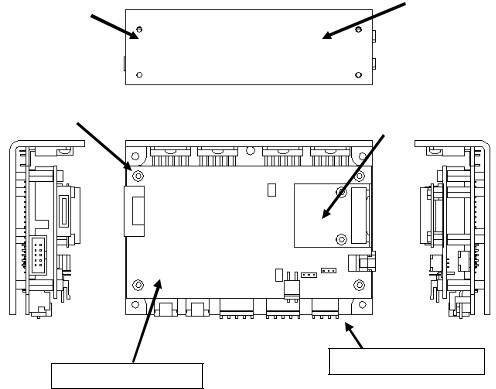
Mounting |
screw |
|
|
|
Heat radiation |
|
|
hole (M3 × 4) |
|
|
|
frame |
||
|
|
|
|
|
|
|
|
|
Mounting |
screw |
|
|
|
|
|
|
hole (φ3.5 × 4) |
|
IF board |
|
|||
|
|
|
|
|
|
|
|
Analog board (lower)
Digital board (upper)
CANON Digital Galvano Scanner System GM-1000 Series
Users Manual 1.20
7
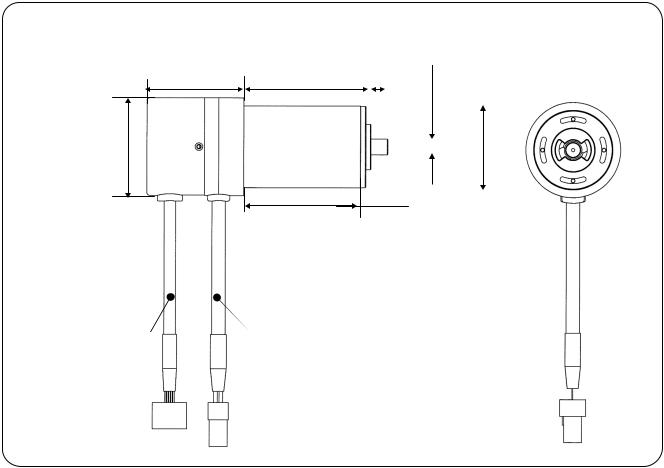
2.3. Dimensions
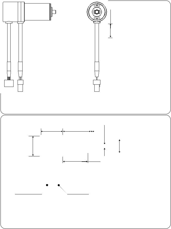
GM-1010
36 |
36 |
6 |
φ33
-0.005 φ5 -0.015 |
0 φ22 -0.03 |
|
|
|
|
|
|
|
|
|
|
|
|
|
32 (Clamp area)
Encoder cable |
Motor cable |
GM-1015
36 46
φ33
Encoder cable |
Motor cable |
|
6 |
|
0.005- 0.015-6φ |
-0 -28φ003 |
|
|
|
|
|
|
|||||
|
|
|
|
|
|
|
|
|
|
|
|
|
|
|
|
|
|
|
|
|
|
|
|
|
|
|
|
|
|
|
|
|
|
|
|
|
|
|
|
|
|
|
|
|
|
|
|
|
|
|
|
|
|
|
|
42 (Clamp area)
CANON Digital Galvano Scanner System GM-1000 Series
Users Manual 1.20
8
GM-1020
42.7 56
φ43
Encoder Cable |
Motor Cable |
|
-0.005 |
φ7 -0.015 |
-0 φ36 -003 |
|
|
|||
|
7.5 |
|
||||||
|
|
|
|
|
|
|||
|
|
|
|
|
|
|
|
|
|
|
|
|
|
|
|
|
|
|
|
|
|
|
|
|
|
|
|
|
|
|
|
|
|
|
|
|
|
|
|
|
|
|
|
|
|
|
|
|
|
|
|
|
|
51.4 (Clamp Area)
CANON Digital Galvano Scanner System GM-1000 Series
Users Manual 1.20
9
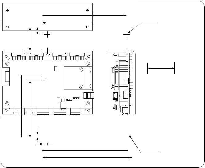
GC-201
10 |
|
|
7 |
118 |
4-M3 |
|
|
|
|
||||
|
|
|||||
|
|
|
|
|||
|
|
|
|
|
||
|
|
|
|
|
|
|
|
|
|
|
|
|
|
|
|
|
|
|
|
|
33
38
88 |
80 |
5 |
|
|
|
|
|
|
|
|
|
|
||
|
|
|
|
|
|
|
|
|
|
|
|
|
|
|
|
|
|
|
|
|
|
|
|
|
|
|
|
|
|
|
|
|
5 |
120 |
|
|
4-φ3.5 |
|
|
|
|
|
|
|
|
||||||
|
|
|
|
|
|
|
|
|
||||
|
|
|
|
|
|
|||||||
|
|
|
|
|
|
|
|
|
||||
|
|
|
|
|
|
|
|
|
|
|
||
|
|
|
|
|
|
|
|
|
125 |
|
|
|
|
|
|
|
|
|
|
|
|
|
|
|
|
CANON Digital Galvano Scanner System GM-1000 Series
Users Manual 1.20
10
Power supply specifications |
|
|
|
+24 V ± 10% |
(For motor drive) |
Peak |
10 A × 2 axes |
|
|
RMS |
2.5 A × 2 axes |
(RMS value differs according to operating conditions, the above conditions GM-1010, Ymirror ±5°, 200Hz)
+5 V ± 5% (For control circuit) 2.8 A
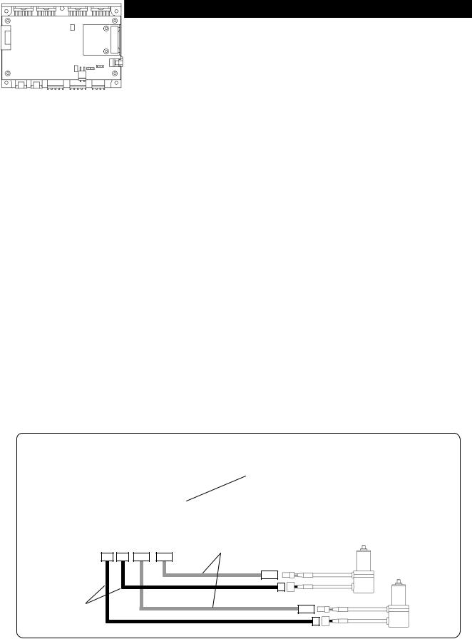
2.5. Connections
IF board
|
|
|
|
|
|
|
|
|
|
|
|
|
|
|
|
|
|
|
|
|
|
|
|
|
|
|
|
|
|
|
|
|
|
|
|
|
|
|
|
|
|
|
|
|
|
|
|
|
|
|
|
|
|
|
|
|
|
|
High-speed serial |
|
|
|
|
|
|
|
|
|
|
|
|
|
|
|
|
|
|
||
|
|
|
|
|
|
|
|
|
|
|
|
|
|
|
|
|
|
|
|
|
|
|
|
|
|
|
|
|
|
|
|
|
|
|
|
|
communication |
||
Digital |
|
|
|
|
|
|
|
|
|
|
|
|
|
|
|
|
|
||
|
|
|
|
|
|
|
|
|
|
|
|
|
|
|
|
||||
input/output |
|
|
|
|
|
|
|
|
|
|
|
|
|
|
|
|
|||
|
|
|
|
|
|
|
|
|
|
|
|
|
|
RS-232C |
|||||
|
|
|
|
|
|
|
|
|
|
|
|
|
|
||||||
|
|
|
|
|
|
|
|
|
|
|
|
|
|
|
|
|
|
|
|
|
|
|
|
|
|
|
|
|
|
|
|
|
|
|
|
|
|
|
|
|
|
|
|
|
|
|
|
|
|
|
|
|
|
|
|
|
|
|
|
|
|
|
|
|
|
|
|
|
|
|
|
|
|
|
|
|
|
|
|
+24 V power
+5 V power
Axis 2
Axis 1
Galvano motor
CANON Digital Galvano Scanner System GM-1000 Series
Users Manual 1.20
11
 Note:
Note:
Connecting the power +24 V, and GND in reverse will damage the GC-201 controller. Take caution when connecting.
Connecting the power +5 V, and GND in reverse will damage the GC-201 controller. Take caution when connecting.
+5V
+ 
 +24V
+24V
CANON Digital Galvano Scanner System GM-1000 Series
Users Manual 1.20
12

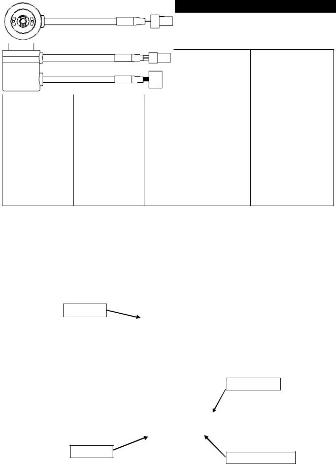
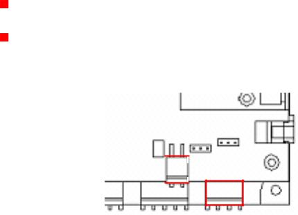
2.6. Connector and Pin Assignment
(Connector types)
|
|
|
|
|
|
|
|
|
|
|
|
|
|
|
|
|
|
|
|
|
|
|
|
|
|
|
|
|
|||
|
|
|
|
|
|
|
|
|
|
|
|
|
|
|
|
|
|
|
|
|
|
|
|
Axis 1 motor encoder connector
Axis 2 motor encoder connector
+5 V power supply
+24 V power supply
RS-232C
High-speed serial communication
Digital input/output
Analog monitor
Fan power supply (+24 V)
CANON Digital Galvano Scanner System GM-1000 Series
Users Manual 1.20
13

(Connector model number & pin assignment)
+5 V power supply
(Connector model number)
|
Connector |
|
Model No. |
|
Manufacturer |
||
|
Board side |
S2P-VH |
|
JST |
|||
|
Cable side |
VHR-2N |
|
JST |
|||
(Connector pin assignment) |
|
|
|||||
|
|
|
|
|
|
|
|
|
Pin No. |
|
|
|
Signal Description |
||
|
1 |
|
+5 V |
|
|
||
|
2 |
|
GND |
|
|
||
|
|
|
|
||||
|
+24 V power supply |
|
|
|
|||
(Connector model number) |
|
|
|||||
|
|
|
|
|
|
|
|
|
Connector |
|
Model No. |
|
Manufacturer |
||
|
Board side |
S4P-VH |
|
JST |
|||
|
Cable side |
VHR-4N |
|
JST |
|||
(Connector pin assignment) |
|
|
|||||
|
|
|
|
|
|
|
|
|
Pin No. |
|
|
|
Signal Description |
||
|
1 |
|
+24 V input for Axis 1 |
|
|
||
|
2 |
|
+24 V input for Axis 2 |
|
|
||
|
3,4 |
|
GND |
|
|
||
|
|
|
|
|
|
||
|
RS-232C |
|
|
|
|
|
|
(Connector model number) |
|
|
|||||
|
|
|
|
|
|
||
|
Connector |
|
Model No. |
|
Manufacturer |
||
|
Board side |
S03B-PASK-2 |
|
JST |
|||
|
Cable side |
PAP-03V-S |
|
JST |
|||
(Connector pin assignment) |
|
|
|||||
|
|
|
|
|
|
||
|
Pin No. |
|
|
|
Signal Description |
||
|
1 |
|
Send data (Signal level complying with RS-232C) |
||||
|
2 |
|
Receive data (Signal level complying with RS-232C) |
||||
|
3 |
|
GND |
|
|
||
CANON Digital Galvano Scanner System GM-1000 Series
Users Manual 1.20
14

High-speed Serial Communication
(Connector model number)
|
Connector |
|
Model No. |
|
Manufacturer |
|
|
Board side |
SM12B-PASS-1-TB |
|
JST |
||
|
Cable side |
PAP-12V-S |
|
|
JST |
|
(Connector pin assignment ) |
|
|
|
|||
|
|
|
|
|
|
|
|
Pin No. |
|
Signal Name |
|
Signal Description |
|
|
1 |
|
CLK- |
|
Clock (-) |
|
|
2 |
|
CLK+ |
|
Clock (+) |
|
|
3 |
|
FS- |
|
Frame sync (-) |
|
|
4 |
|
FS+ |
|
Frame sync (+) |
|
|
5 |
|
DAT(AXIS |
1) - |
Axis 1 |
Target position data (-) |
|
6 |
|
DAT(AXIS |
1) |
Axis 1 |
Target position data (+) |
|
7 |
|
DAT(AXIS |
2) - |
Axis 2 |
Target position data (-) |
|
8 |
|
DAT(AXIS |
2) |
Axis 2 |
Target position data (+) |
|
9 |
|
STS- |
|
Status (-) |
|
|
10 |
|
STS+ |
|
Status (+) |
|
|
11 |
|
GND |
|
System GND |
|
|
12 |
|
FG |
|
Frame GND |
|
The signal levels depend on the IF board.
GC-422 - Receiver: AM26LV32C (TI), Driver: SN75179B (TI)
GC-LVDS - Receiver: SN65LVDS32 (TI), Driver: SN65LVDS179 (TI)
Digital I/O
See 5.1. “Connector Pin Assignment”
Analog Monitor
See 5.1. “Connector Pin Assignment”
CANON Digital Galvano Scanner System GM-1000 Series
Users Manual 1.20
15

Cooling Fan Power Supply
(Connector model number)
|
Connector |
Model No. |
|
Manufacturer |
|
|
Board side |
S04B-PASK-2 |
|
JST |
|
|
Cable side |
PAP-04V-S |
|
JST |
|
(Connector pin arrangement) |
|
|
|||
|
|
|
|
|
|
|
Pin No. |
|
|
Signal Description |
|
|
1 |
+24 V Output |
|
|
|
|
2 |
GND |
|
|
|
|
3 |
(No connection) |
|
|
|
|
4 |
(No connection) |
|
|
|
CANON Digital Galvano Scanner System GM-1000 Series
Users Manual 1.20
16
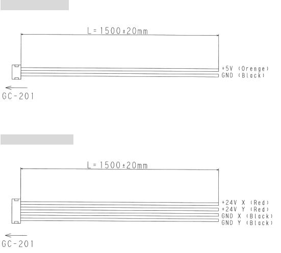
2.7. Optional Cables
Optional cables are prepared for power and communications cables. Connector pin assignment for each cable as follows.
Verify details with your sales representative.
Option cables
|
Power cable (+5 V) |
|
|
|
Power cable (+24 V) |
|
|
|
RS-232C cable |
|
|
|
High-speed serial communication cable |
|
|
Power Cable +5 V
Power Cable +24 V
CANON Digital Galvano Scanner System GM-1000 Series
Users Manual 1.20
17
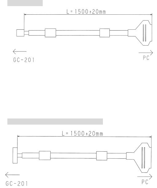
RS-232C Cable
PC side (D-sub 9 pin)
Pin |
Signal |
2 |
RX |
|
|
3 |
TX |
|
|
5 |
GND |
|
|
High-Speed Serial Communication Cable
PC side (D-sub 25pin)
|
Pin |
Signal |
|
Pin |
|
Signal |
|
1 |
Clock - |
|
14 |
|
Clock + |
|
2 |
FS - |
|
15 |
|
FS + |
|
3 |
Data (Axis 1) - |
|
16 |
|
Data (Axis 1) + |
|
4 |
Data (Axis 2) - |
|
17 |
|
Data (Axis 2) + |
|
5 |
Do not connect |
|
18 |
|
Do not connect |
|
6 |
Status - |
|
19 |
|
Status + |
|
7 |
Do not connect |
|
20 |
|
Do not connect |
|
8 |
Do not connect |
|
21 |
|
Do not connect |
|
9 |
Do not connect |
|
22 |
|
Do not connect |
|
10 |
Do not connect |
|
23 |
|
GND |
|
11 |
GND |
|
24 |
|
GND |
|
12 |
Do not connect |
|
25 |
|
Do not connect |
|
13 |
Do not connect |
|
|
|
|
CANON Digital Galvano Scanner System |
GM-1000 Series |
|
||||
Users Manual 1.20 |
|
|
|
|
|
|
18

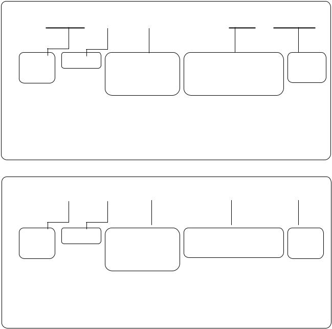
2.8. Control Specifications
The controller (GC-201) is operated by:
•RS-232C command input
•High-speed serial communication
|
|
|
|
RS-232C |
|
|
|
|
|
|
|
|
|
|
|
|
|
|
High-speed serial communication |
|
|||||
|
|
|
|
communication command input |
|
|
|
|||||
|
|
|
|
|
|
|
|
|
|
|
|
|
|
|
|
|
|
||||||||
|
|
|
- Raster scan and step movement etc. - Vector scans with control over the |
|||||||||
|
|
|
|
can be performed easily. |
|
desired locations of two axes are |
||||||
|
|
|
|
|
|
|
possible. This is used in laser |
|||||
|
|
|
- In order to obtain synchronization |
|
marking etc. |
|
|
|
|
|||
|
|
|
|
with external equipment, operation |
|
|
|
|
|
|
|
|
|
|
|
|
can be started with an external |
|
- Complete |
synchronization |
with |
||||
|
|
|
|
trigger signal. (Fluctuating delays |
|
external equipment can be obtained |
||||||
|
Features |
|
may occur within the internal control |
|
in order to use high-speed serial |
|||||||
|
|
|
|
sampling time.) |
|
communication |
clock pulses |
by |
||||
|
|
|
|
|
|
|
controlling the controller. |
|
|
|
||
|
|
|
|
|
|
|
- As it can be operated with XY2-100 |
|||||
|
|
|
|
|
|
|
communication |
specifications, |
a |
|||
|
|
|
|
|
|
|
controller compliant with XY2-100 |
|||||
|
|
|
|
|
|
|
can be connected. |
|
|
|
||
|
|
|
|
|
|
|
||||||
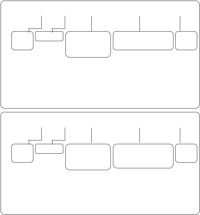
|
Target position |
|
RS-232C communication command |
High-speed serial communication |
|
|
||||||
|
command |
|
|
|
|
|
|
|
|
|
|
|
|
|
|
RS-232C communication command |
RS-232C communication command |
|
|
||||||
|
Operation |
|
|
|
|
|||||||
|
setting |
|
|
|
|
|
|
|
|
|
|
|
|
parameter |
|
|
|
|
|
|
|
|
|
|
|
|
setting |
|
|
|
|
|
|
|
|
|
|
|
|
Control clock |
|
|
Uses the controller GC-201 internal |
|
Uses |
high-speed |
serial |
||||
|
|
|
|
|||||||||
|
|
|
circuit clock pulses |
|
communication clock pulses |
|
|
|
||||
|
|
|
|
|
|
|
|
|||||
|
|
|
|
|
|
|
|
|
|
|
|
|
|
|
|
|
|
|
|
|
|
|
|
|
|
- A target position command input by an RS-232C communication command, or a target position command from a high-speed serial communication can be mutually switched with a command. (See
2.8.5.“RS-232C Communication Command Input and High-Speed Communication Switching”)
CANON Digital Galvano Scanner System GM-1000 Series
Users Manual 1.20
19
-With the default settings at shipping, power-on starts up the controller with in RS-232 Communication Command Input mode.
-The parameter can be set to determine which mode the controller starts after power-on. (See 6.1. “Setting Controller Start Up Mode”)
Note:
For start up when set to the High-Speed Serial Communication mode, in order to use high-speed serial communication clock pulses internally, signal input by high-speed serial communication is necessary at power-on. When there is no signal input, a Clock Lack error occurs. (See 10.2. “Errors”) After an error occurs, and input of a high-speed serial communication signal begins correctly, operation begins automatically from the high-speed serial communication signal.
CANON Digital Galvano Scanner System GM-1000 Series
Users Manual 1.20
20
2.8.1. Number of Encoder Pulses
This section explains the relationship between the galvano scanner motor rotating angle and the number of encoder pulses.
Control commands and some of the parameter angle settings use the number of encoder pulses.
The controller divides one encoder cycle into 8,192, and this is the number of encoder pulses. Depending on the type of encoder included on the motor, caution is necessary as the number of pulses for the same specified angle can differ.
Many commands use pulses as a unit in the RS-232C communication command parameter data used for operations.
In the case of the GM-1010 for example
1 rotation (360°) = 1,000 cycles = 1,000 × 8,192 = 8,192,000 pulses 1° (angle of equipment) = 8,192,000 pulses × 1 / 360 = 22,756 pulses Resolution = 360° ÷ 8,192,000 pulses = 0.0000429° = 0.77 urad
Each motor is as follows.
|
Motor type |
|
|
GM-1010 |
|
|
GM-1015, GM-1020 |
|
|
|
|
|
|
|
|
|
|
|
Included encoder cycles / 1 |
|
1,000 cycles |
|
1,500 cycles |
|||
|
rotation 360° |
|
|
|||||
|
|
|
|
|
|
|
||
|
|
|
|
|
|
|||
|
Number of pulses |
|
8,192,000 pulses |
|
12,288,000 pulses |
|||
|
|
|
|
|
|
|||
|
Command resolution (1 pulse) |
|
0.77 urad |
|
0.51 urad |
|||
|
|
|
|
|
|
|
|
|
CANON Digital Galvano Scanner System GM-1000 Series
Users Manual 1.20
21
2.8.2. RS-232C command input
RS-232C command input allows the following:
•Operation setting
•Parameter setting
•Error processing
•Status check
(For details, see 8. “Commands”)
In case not using high-speed serial communication, RS-232C communication command input is enough for the following function:
•Step movement
•Raster scan (Continuous oscillation of a certain angle at a fixed frequency)
(Communication specifications)
Wiring |
Cross wiring |
|
|
Communication rate |
38400 bps |
|
|
Data length |
8 bits |
|
|
Stop bit |
1 |
|
|
Parity |
None |
|
|
Data format |
ASCII code |
|
|
Delimiter code |
LF (0x0a) or CR (0x0d) |
|
|
CANON Digital Galvano Scanner System GM-1000 Series
Users Manual 1.20
22
(Command specifications)
In response to command send, the controller returns a reply with data.
The data contents depend on the command. (For details, see 8.2. “Command Details”)
Command send |
|
A Axis No. C Command ID / Data |
Delimiter |
Axis No. |
Command |
Command ID |
|
Data |
|
|
Delimiter |
||
1 or 2 |
|
Decimal, 3-digit |
|
Added |
to |
command as |
LF or CR |
||
|
(See 7.1 for details) |
|
|||||||
|
|
|
required (decimal) |
|
|||||
|
|
|
|
|
|
|
|||
E.g. Servo ON ID = 4 |
Data = 1 |
|
|
|
|
|
|
|
|
A1C004 / 1 (LF) |
|
|
|
|
|
|
|
|
|
(ASCII code: 0x41 0x31 0x43 0x30 0x30 0x34 0x2f 0x31 0x0a) |
|
||||||||
|
|
A |
1 |
C 0 |
0 |
4 |
/ |
1 (LF) |
|
Command reply |
|
A Axis No. C Command ID / Data |
Delimiter |
Axis No. |
Command |
Command ID |
|
Return value |
Delimiter |
|||
1 or 2 |
|
Decimal, 3-digit |
|
|
|
LF or CR |
||
|
|
(See 7.1 for details) |
|
|
|
|
||
E.g. Servo ON ID = 4 |
Data = 1 |
|
|
|
|
|
|
|
A1C004 / 1 (LF) |
|
|
|
|
|
|
|
|
(ASCII code: 0x41 0x31 0x43 0x30 0x30 0x34 0x2f 0x31 0x0a) |
|
|||||||
|
|
A |
1 |
C 0 |
0 |
4 |
/ 1 |
(LF) |
CANON Digital Galvano Scanner System GM-1000 Series
Users Manual 1.20
23
Parameters of the GC-201 can be changed by the following sending method to the controller. Also in response to parameters sent, the controller always returns a reply with data.
The data contents depend on the command. (For details, see 9.2. “Parameter Details”)
When a parameter is changed, in order to start up with the same setting the next time power is turned on, it is necessary to write the changed parameter to the ROM.
(See 9.4. “Writing Parameters into ROM” for methods of writing to ROM with control software)
(Note: Carry out writing parameters to ROM only after thoroughly verifying the content. Depending on the changed values, the controller may not start normally.)
Parameter send |
|
|
|
|
|
|
A |
Axis No. |
P |
Parameter ID |
/ |
Data |
Delimiter |
Axis No. |
Parameter |
Command ID |
Parameter setting |
Delimiter |
1 or 2 |
|
Decimal, 3-digit |
Decimal |
LF or CR |
|
(See 7.1 for details) |
|||
|
|
|
|
E.g. LQ gain parameter |
ID = 6 |
Data = 4500 |
|
|
|
|
|
A1P006 / 4500 (LF) |
|
|
|
|
|
|
|
(ASCII code: 0x41 0x31 0x50 0x30 0x30 0x36 0x2f 0x34 0x35 0x30 0x30 0x0a) |
|||||||
A |
1 |
P 0 |
0 |
6 |
/ 4 |
5 |
0 0 (LF) |
Parameter reply
A |
Axis No. |
P |
Parameter ID |
/ |
Data |
Delimiter |
Axis No. |
Parameter |
Command ID |
|
|
Parameter |
setting |
Delimiter |
||
1 or 2 |
|
Decimal, 3-digit |
|
successful / unsuccessful |
LF or CR |
||||
|
(See 7.1 for details) |
|
|||||||
|
|
|
0 or 1 |
|
|
|
|||
|
|
|
|
|
|
|
|
|
|
E.g. LQ gain parameter |
ID = 6 |
Data = 4500 |
|
|
|
|
|
||
A1P006 / 4500 (LF) |
|
|
|
|
|
|
|
|
|
(ASCII code: 0x41 0x31 0x50 0x30 0x30 0x36 0x2f 0x30 0x0a) |
|
||||||||
|
A |
1 |
P 0 |
0 |
6 |
/ |
0 |
(LF) |
|
CANON Digital Galvano Scanner System GM-1000 Series
Users Manual 1.20
24

Writing parameters to ROM is also possible with commands via RS-232C.
When writing parameters to ROM, a reply that definitely contains data will be sent by a controller. The content of data is different by a parameter. (For details, see 9.2. “Parameter Details”)
(Note: Carry out writing parameters to ROM only after thoroughly verifying the content. Depending on the changed values, the controller may not start normally.)
Parameter ROM Write send
E |
Axis No. |
P |
Parameter ID |
/ |
Data |
Delimiter |
Axis No. |
Parameter |
Parameter ID |
Parameter setting |
Delimiter |
1 or 2 |
|
Decimal, 3-digit |
Decimal |
LF or CR |
|
(See 7.1 for details) |
|||
|
|
|
|
E.g. LQ gain parameter |
ID = 6 |
Data = 4500 |
|
|
|
|
|
E1P006 / 4500 (LF) |
|
|
|
|
|
|
|
(ASCII code: 0x45 0x31 0x50 0x30 0x30 0x36 0x2f 0x34 0x35 0x30 0x30 0x0a) |
|||||||
E |
1 |
P 0 |
0 |
6 |
/ 4 |
5 |
0 0 (LF) |
Parameter ROM Write reply
E |
Axis No. |
P |
Parameter ID |
/ |
Data |
Delimiter |
Axis No. |
Parameter |
Parameter ID |
|
|
Parameter |
setting |
Delimiter |
||
1 or 2 |
|
Decimal, 3-digit |
|
successful / unsuccessful |
LF or CR |
||||
|
(See 7.1 for details) |
|
|||||||
|
|
|
0 or 1 |
|
|
|
|||
|
|
|
|
|
|
|
|
|
|
E.g. LQ gain parameter |
ID = 6 |
Data = 4500 |
|
|
|
|
|
||
E1P006 / 4500 (LF) |
|
|
|
|
|
|
|
|
|
(ASCII code: 0x45 0x31 0x50 0x30 0x30 0x36 0x2f 0x30 0x0a) |
|
||||||||
|
E |
1 |
P 0 |
0 |
6 |
/ |
0 |
(LF) |
|
CANON Digital Galvano Scanner System GM-1000 Series
Users Manual 1.20
25

2.8.3. High-speed serial communication
To control the mirror to an arbitrary position by marking or any other application, target position data updated as required can be given to the controller by using high-speed serial communication.
By setting, the controller can be started up in the mode of tracking a target position specified by high-speed serial communication. (For details, see 6.1. “Setting Controller Start Up Mode”)
(Communication specifications)
|
Base clock (CLK) |
|
|
|
|
|
|
|
|
|
|
|
|
|
|
|
|
|
|
|
|
|
|
2 MHz |
|
|
|
|
|
|
|
|
|
|
|
|
|
|
|
|
|
||||||||||||
|
|
|
|
|
|
|
|
|
|
|
|
|
|
|
|
|
|
|
|
|
|
|
|
|
|
|
|
|
|
|
|
|
|
|
|
|
|
|
|
|
|
|
|
|
|
|
|
|
|
|
|
|
|
|
Frame sync (FS) |
|
|
|
|
|
|
|
|
|
|
|
|
|
|
|
|
|
|
|
|
|
100 kHz |
|
|
|
|
|
|
|
|
|
|
|
|
|
|
|
|
|
|||||||||||||
|
|
|
|
|
|
|
|
|
|
|
|
|
|
|
|
|
|
|
|
|
|
|
|
|
|
|
|
|
|
|
|
|
|
|
|
|
|
|
|
|
|
|
|
|
|
|
|
|
|
|
|
|
|
|
Data (DAT) |
|
|
|
|
|
|
|
|
|
|
|
|
|
|
|
|
|
|
|
20 bits (Position data: 16 bits) |
|
|
|
|
|
|
|
|
|
|
|
|||||||||||||||||||||
|
|
|
|
|
|
|
|
|
|
|
|
|
|
|
|
|
|
|
|
|
|
|
|
|
|
|
|
|
|
|
|
|
|
|
|
|
|
|
|
|
|
|
|
|
|
|
|
|
|
|
|
|
|
|
Status (STS) |
|
|
|
|
|
|
|
|
|
|
|
|
|
|
|
|
|
|
|
|
|
|
|
|
|
20 bits |
|
|
|
|
|
|
|
|
|
|
|
|
|
|
|
|
|
|||||||||
|
|
|
|
|
|
|
|
|
|
|
|
|
|
|
|
|
|
|
|
|
|
|
|
|
|
|
|
|
|
|
|
|
|
|
|
|
|
|
|
|
|
|
|
|
|
|
|
|
|
|
|
|
|
|
Transmission system |
|
|
|
|
|
|
|
|
|
|
|
|
|
|
|
|
Differential signal |
|
|
|
|
|
|
|
|
|
|
|
|
|
|
|||||||||||||||||||||
|
|
|
|
|
|
|
|
|
|
|
|
|
|
|
|
|
|
|
|
|
|
|
|
|
|
|
|
|
|
|
|
|
|
|
|
|
|
|
|
|
|
|
|
|
|
|
|
|
|
|
|
|
|
|
Signal level |
|
|
|
|
|
|
|
|
|
|
|
|
|
|
|
|
|
|
|
|
|
|
|
5V-TTL, LVDS |
|
|
|
|
|
|
|
|
|
|
|
|
|
|
|
|||||||||||||
|
|
|
|
|
|
|
|
|
|
|
|
|
|
|
|
|
|
(Selectable by the optional IF board) |
|
|
|
|
|
|
|
|
|
||||||||||||||||||||||||||
|
|
|
|
|
|
|
|
|
|
|
|
|
|
|
|
|
|
|
|
|
|
|
|
|
|
|
|
|
|
|
|
|
|
||||||||||||||||||||
|
|
|
|
|
|
|
|
|
|
|
|
|
|
|
|
|
|
|
|
|
|
|
|
|
|
|
|
|
|
|
|
|
|
|
|
|
|
|
|
|
|
|
|
|
|
|
|
|
|
|
|
|
|
(Timing Diagram) |
|
|
|
|
|
|
|
|
|
|
|
|
|
|
|
|
|
|
|
|
|
|
|
|
|
|
|
|
|
|
|
|
|
|
|
|
|
|
|
|
|
|
|
|
|
|
|||||||
|
|
|
|
|
|
|
|
|
|
|
|
|
|
|
|
|
|
|
|
|
|
|
|
|
|
|
|
|
|
|
|
|
|
|
|
|
|
|
|
|
|
|
|
|
|
|
|||||||
Timing Diagram |
|
|
|
|
|
|
|
|
|
|
|
|
|
|
|
|
|
|
|
|
|
|
|
|
|
|
|
|
|
|
|
|
|
|
|
|
|
|
|
|
|
|
|
|
|
|
|||||||
|
|
|
|
|
|
|
2MHz |
|
|
|
|
|
|
|
|
|
|
|
|
|
|
|
|
|
|
|
|
|
|
|
|
|
|
|
|
|
|
|
|
|
|
|
|
|
|
|
|
|
|
|
|||
CLK |
1 |
2 |
|
3 |
|
|
4 |
5 |
|
6 |
|
7 |
8 |
9 |
10 |
11 |
12 |
13 |
14 |
|
15 |
|
16 |
17 |
|
18 |
|
19 |
20 |
|
|
|
|
|
|
||||||||||||||||||
|
|
|
|
|
|
|
|
|
|
|
|
|
|
|
|
|
|
|
|
|
|
|
|
|
|
|
|
|
|
|
|
|
|
|
|
|
|
|
|
|
|
|
|
|
|
|
|
|
|
|
|
||
FS |
|
|
|
|
|
|
|
|
|
|
|
|
|
|
|
|
|
|
|
|
|
|
|
|
|
|
|
|
|
|
|
|
|
|
|
|
|
|
|
|
|
|
|
|
|
|
|
|
|
|
|
|
|
|
|
|
|
|
|
|
|
|
|
|
|
|
|
|
|
|
|
|
|
|
|
|
|
|
|
|
|
|
|
|
|
|
|
|
|
|
|
|
|
|
|
|
|
|
|
|
|
|
|
|
|
||
DAT (AXIS 1) |
|
|
|
|
|
|
|
|
|
|
|
|
|
|
|
|
|
|
|
|
|
|
|
|
|
|
|
|
|
|
|
|
|
|
|
|
|
|
|
|
|
||||||||||||
AXIS 1 DATA -1 |
|
AXIS 1 DATA |
|
|
|
|
|
|
|
|
|
|
|
|
|
|
|
|
|
|
|
|
|
|
|
|
|
|
|
|
|
|
|
|
|
|
|
AXIS 1 DATA +1 |
|||||||||||||||
DAT (AXIS 2) |
|
|
|
|
|
|
|
|
|
|
|
|
|
|
|
|
|
|
|
|
|
|
|
|
|
|
|
|
|
|
|
|
|
|
|
|
|
|
|
|
|
||||||||||||
AXIS 2 DATA -1 |
|
AXIS 2 DATA |
|
|
|
|
|
|
|
|
|
|
|
|
|
|
|
|
|
|
|
|
|
|
|
|
|
|
|
|
|
|
|
|
|
|
|
AXIS 2 DATA +1 |
|||||||||||||||
STS |
|
|
|
|
|
|
|
|
|
|
|
|
|
|
|
|
|
|
|
|
|
|
|
|
|
|
|
|
|
|
|
|
|
|
|
|
|
|
|
|
|
|
|
|
|||||||||
Status -1 |
|
Status |
|
|
|
|
|
|
|
|
|
|
|
|
|
|
|
|
|
|
|
|
|
|
|
|
|
|
|
|
|
|
|
|
|
|
|
|
|
|
Status +1 |
||||||||||||
|
|
|
Input Signal to GC-201 |
|
: CLK , FS , DAT |
|
|
|
|
|
|
|
|
|
|
|
|
|
|
|
|
|
|
|
|
|
|
|
|
|
|
|
|
|
|
||||||||||||||||||
|
|
|
Ounput Signal from GC-201 |
|
: STS |
|
|
|
|
|
|
|
|
|
|
|
|
|
|
|
|
|
|
|
|
|
|
|
|
|
|
|
|
|
|
|
|
|
|
|
|
||||||||||||
As indicated in the above timing diagram, it is necessary to always continuously input the CLK, FS, and DAT signals to the GC-201. In the event that the signal is disconnected, or the signal’s timing is incorrect, the GC-201 will output an error signal (Clock Lack). (For details, See 10.2. “Errors”.)
When switching to high-speed serial communication mode, or starting up in high-speed serial communication mode when turning on the controller’s power supply, input of the high-speed serial communication signal (all of CLK, FS, and DAT) beforehand is necessary.
For the support of other communication specifications, contact the Sales Department.
CANON Digital Galvano Scanner System GM-1000 Series
Users Manual 1.20
26

(Target Position Data) DAT (AXIS1), DAT (AXIS 2)
It is possible to switch the length of data used as target position data from the DAT (AXIS1), DAT (AXIS 2) 20 bit (every 100 kHz) signals. Please set appropriately to match the signal specifications of the scanner controller that outputs a high-speed serial communication signal, and other output equipment.
Note: The length of data input in the GC-201 is always 20 bit (every 100 kHz). The bits of the target position data that get used and sent are switched from within 20 bit data.
When there is a big difference in the target position specified in the high-speed serial communication, and the actual operation position, it is possible this parameter setting is incorrect. Please verify.
The data length of the target position data by the high-speed serial communication can be changed by two following parameters.
(Target position data length)
Can be changed by 16 bit – 20 bit.
Parameter ID |
|
DATA |
|
|
|
|
16: 16bit |
Data * |
|
17: 17bit |
Data |
67 |
18: 18bit |
Data |
|
19: 19bit |
Data |
|
20: 20bit |
Data |
|
|
|
(Data position)
The least significant bit position of the target position data of high-speed serial communication 20bit data can be set by following parameter. The specified number of bits is shifted right, making the target position data.
Parameter ID |
|
DATA |
|
|
|
|
0: 0bit |
position |
|
1: 1bit |
position * |
68 |
2: 2bit |
position |
|
3: 3bit |
position |
|
4: 4bit |
position |
|
|
|
With the default settings at shipping, the setting is * (16 bit position data length, data least significant bit 1 bit position). This communication specification is compatible with XY2-100. When using the scanner controller of XY2-100 specifications, please use this setting.
CANON Digital Galvano Scanner System GM-1000 Series
Users Manual 1.20
27

Examples of the settings are as follows.
(Example 1) Parameter ID = 67 |
16 |
|
|
|
|
|
|
|
|
|
|
|
|
|
|
|
|
||||||
|
Parameter ID = 68 |
1 |
|
|
|
|
|
|
|
|
|
|
|
|
|
|
|
|
|||||
|
XY2-100 specification compatible |
|
|
|
|
|
|
|
|
|
|
|
|
|
|
|
|
||||||
|
|
|
|
|
|
|
|
|
|
|
|
|
|
|
|
|
|
|
|
|
|
|
|
|
Bit |
1 |
2 |
3 |
4 |
5 |
6 |
7 |
8 |
9 |
10 |
11 |
|
12 |
13 |
14 |
15 |
16 |
17 |
18 |
19 |
20 |
|
|
DATA (AXIS 1) |
N |
N |
N |
D15 |
D14 |
D13 |
D12 |
D11 |
D10 |
D9 |
D8 |
|
D7 |
D6 |
D5 |
D4 |
D3 |
D2 |
D1 |
D0 |
N |
|
|
DATA (AXIS 2) |
N |
N |
N |
D15 |
D14 |
D13 |
D12 |
D11 |
D10 |
D9 |
D8 |
|
D7 |
D6 |
D5 |
D4 |
D3 |
D2 |
D1 |
D0 |
N |
|
|
|
|
|
|
|
|
|
|
|
|
|
16bit |
|
|
|
|
|
|
|
|
1bit |
||
|
|
|
|
|
|
|
|
|
|
(Parameter ID = 67) |
|
|
|
|
(Parameter ID = 68) |
||||||||
Note: The above N bit data is not used. It does not matter if it is either 1 or 0.
(Example 2) Parameter ID = 67 |
16 |
|
|
|
|
|
|
|
|
|
|
|
|
|
|
||||||
|
Parameter ID = 68 |
3 |
|
|
|
|
|
|
|
|
|
|
|
|
|
|
|||||
|
|
|
|
|
|
|
|
|
|
|
|
|
|
|
|
|
|
|
|
|
|
|
Bit |
1 |
2 |
3 |
4 |
5 |
6 |
7 |
8 |
9 |
10 |
11 |
12 |
13 |
14 |
15 |
16 |
17 |
18 |
19 |
20 |
|
DATA (AXIS 1) |
N |
D15 |
D14 |
D13 |
D12 |
D11 |
D10 |
D9 |
D8 |
D7 |
D6 |
D5 |
D4 |
D3 |
D2 |
D1 |
D0 |
N |
N |
N |
|
DATA (AXIS 2) |
N |
D15 |
D14 |
D13 |
D12 |
D11 |
D10 |
D9 |
D8 |
D7 |
D6 |
D5 |
D4 |
D3 |
D2 |
D1 |
D0 |
N |
N |
N |
16bit |
|
3bit |
|
|
(Parameter |
||
(Parameter |
ID = 67) |
ID = 68) |
(Example 3) Parameter ID = 67 |
18 |
|
|
|
|
|
|
|
|
|
|
|
|
|
|
||||||
|
Parameter ID = 68 |
|
2 |
|
|
|
|
|
|
|
|
|
|
|
|
|
|
||||
|
|
|
|
|
|
|
|
|
|
|
|
|
|
|
|
|
|
|
|
|
|
|
Bit |
1 |
2 |
3 |
4 |
5 |
6 |
7 |
8 |
9 |
10 |
11 |
12 |
13 |
14 |
15 |
16 |
17 |
18 |
19 |
20 |
|
DATA (AXIS 1) |
D17 |
D16 |
D15 |
D14 |
D13 |
D12 |
D11 |
D10 |
D9 |
D8 |
D7 |
D6 |
D5 |
D4 |
D3 |
D2 |
D1 |
D0 |
N |
N |
|
DATA (AXIS 2) |
D17 |
D16 |
D15 |
D14 |
D13 |
D12 |
D11 |
D10 |
D9 |
D8 |
D7 |
D6 |
D5 |
D4 |
D3 |
D2 |
D1 |
D0 |
N |
N |
18bit |
2bit |
|
||
(Parameter |
ID = 68) |
|||
|
ID = 67) |
|||
(Parameter |
|
|
|
|
|
|
|
|
|
(Example 4) Parameter ID = 67 |
20 |
|
|
|
|
|
|
|
|
|
|
|
|
|
|
||||||
|
Parameter ID = 68 |
|
0 |
|
|
|
|
|
|
|
|
|
|
|
|
|
|
||||
|
|
|
|
|
|
|
|
|
|
|
|
|
|
|
|
|
|
|
|
|
|
|
Bit |
1 |
2 |
3 |
4 |
5 |
6 |
7 |
8 |
9 |
10 |
11 |
12 |
13 |
14 |
15 |
16 |
17 |
18 |
19 |
20 |
|
DATA (AXIS 1) |
D19 |
D18 |
D17 |
D16 |
D15 |
D14 |
D13 |
D12 |
D11 |
D10 |
D9 |
D8 |
D7 |
D6 |
D5 |
D4 |
D3 |
D2 |
D1 |
D0 |
|
DATA (AXIS 2) |
D19 |
D18 |
D17 |
D16 |
D15 |
D14 |
D13 |
D12 |
D11 |
D10 |
D9 |
D8 |
D7 |
D6 |
D5 |
D4 |
D3 |
D2 |
D1 |
D0 |
20bit |
0bit |
( ID = 67) |
ID = 68) |
(Parameter |
(Parameter |
CANON Digital Galvano Scanner System GM-1000 Series
Users Manual 1.20
28
This section explains the motor rotating angle for the high-speed serial communication data. Default settings have the following relationships.
Data 1 = 1 pulse (factory setting)
See 2.8.1. “Number of Encoder Pulses" for the relationship between the motor rotating angle and the number of pulses.
In the case of 16 bit data (GM-1010)
|
High-speed communication |
|
Motor |
|
|||
|
Target position data value |
|
|
|
|
|
|
|
|
Number of pluses |
|
|
Motor rotating angle |
|
|
|
16bit |
|
|
|
|
||
|
|
|
|
|
|
|
|
Maximum |
0xFFFF |
|
32767 pulses |
|
1.44 deg |
||
position |
|
|
|||||
|
|
|
|
|
|
|
|
|
|
|
|
|
|
|
|
0 pulse |
0x8000 |
0 |
|
0 |
|
||
position |
|
|
|||||
|
|
|
|
|
|
|
|
|
|
|
|
|
|
|
|
Minimum |
0x0000 |
|
32768 pulses |
|
1.44 deg |
||
position |
|
|
|||||
|
|
|
|
|
|
|
|
|
|
|
|
|
|
|
|
(GM-1015, GM-1020) |
|
|
|
|
|
|
|
|
|
|
|
||||
|
High-speed communication |
|
Motor |
|
|||
|
Target position data value |
|
|
|
|
|
|
|
|
Number of pluses |
|
|
Motor rotating angle |
|
|
|
16bit |
|
|
|
|
||
|
|
|
|
|
|
|
|
Maximum |
0xFFFF |
|
32767 pulses |
|
0.96 deg |
||
position |
|
|
|||||
|
|
|
|
|
|
|
|
|
|
|
|
|
|
|
|
0 pulse |
0x8000 |
0 |
|
0 |
|
||
position |
|
|
|||||
|
|
|
|
|
|
|
|
|
|
|
|
|
|
|
|
Minimum |
0x0000 |
|
32768 pulses |
|
0.96 deg |
||
position |
|
|
|||||
|
|
|
|
|
|
|
|
|
|
|
|
|
|
|
|
Note: The motor rotating angle + direction when viewed from the rotation axis appear as clockwise.
When set to the factory default, rotation is only possible up to angles above.
If a greater angle is specified, set a magnification by using the following parameter.
CANON Digital Galvano Scanner System GM-1000 Series
Users Manual 1.20
29

Parameter ID |
Data |
13 |
|
(High-speed serial communication |
Magnification ×1000 |
conversion gain parameter) |
|
E.g. For x2 (parameter ID = 13 setting: 2000), the following angle can be specified: -1.44 × 2 deg ~ 1.44 × 2 deg (GM-1010)
-0.96 × 2 deg ~ 0.96 × 2 deg (GM-1015, 1020) The command resolution will be two times
CANON Digital Galvano Scanner System GM-1000 Series
Users Manual 1.20
30
Loading...