


FDW75C12N
Product
Instructions
IP Ready™ Series
FDW75C12N & FDP75C12N
Before attempting to connect or operate this product,
please read these instructions completely.
- 1 -
81-IN5329
04/28/06
!
1. Read Instructions - All the safety and operating instructions should be read
!
before the unit is operated.
2. Retain Instructions - The safety and operating instructions should be retained
for future reference.
3. Heed Warnings - All warnings on the unit and in the operating instructions
should be adhered to.
4. Follow Instructions - All operating & user instructions should be followed.
5. Electrical Connections - Only a qualified electrician should make electrical
connections.
Attachments - Do not use attachments not recommended by the product
6.
manufacturer as they may cause hazards.
7. Cable Runs - All cable runs must be within permissible distance.
8. Mounting - This unit must be properly and securely mounted to a supporting
structure capable of sustaining the weight of the unit. Accordingly:
a. Installation
b. Installation should be in compliance with local codes.
c. Care should be exercised to select suitable hardware to install the unit,
taking into account both the composition of the mounting surface and
the weight of the unit. Be sure to periodically examine the unit and the
supporting structure to make sure that the integrity of the installation
is intact. Failure to comply with the foregoing could result in the unit
separating from the support structure and falling, with resultant damages
or injury to anyone or anything struck by the falling unit.
unPaCkinG
Unpack carefully. Electronic components can be damaged if improperly handled
or dropped. If an item appears to have been damaged in shipment, replace it
properly in its carton and notify the shipper.
1. The shipping carton and packaging material. They are the safest material in
which to make future shipments of the equipment.
2. These Installation and Operating Instructions.
should be made by a qualified installer.
Be sure to save:
safEtY PRECautionsiMPoRtant safEGuaRDs
Caution
Risk of
ElECtRiC shoCk!
Caution: to REDuCE thE Risk of
ElECtRiCal shoCk, Do not EXPosE
oMPonEnts to WatER oR MoistuRE.
C
The lightning flash with an arrowhead symbol, within an
equilateral triangle, is intended to alert the user to the
presence of non-insulated "dangerous voltage" within the
product's enclosure that may be of sufficient magnitude
to constitute a risk of electric shock to persons.
The exclamation point within an equilateral triangle is
intended to alert the user to presence of important operating
and maintenance (servicing) instructions in the literature
accompanying the appliance.
sERViCE
If the unit ever needs repair service, customer should contact Videolarm
(1-800-554-1124) for return authorization & shipping instructions.
tEChniCal suPPoRt
Videolarm has set-up a 24 hour technical support line for their customers.
24 houR tEChniCal suPPoRt
1-800-554-1124
LIMITED WARRANTY FOR VIDEOLARM INC. PRODUCTS
VIDEOLARM INC. warrants this Product to be free from defects in material or workmanship, as follows:
PRODUCT CATEGORY PARTS LABOR
All Enclosures and Electronics Three (3) Years Three (3) Years
Pan/Tilts Three
Poles/PoleEvators Three (3) Years Three (3) Years
Warrior/Q-View/I.R. Illuminators Five (5) Years Five (5) Years
Controllers Three
Power Supplies Three (3) Years Three (3) Years
Accessory Brackets Three (3) Years Three (3) Years
During the labor warranty period, to repair the Product, Purchaser will either return the defective product, freight prepaid, or deliver it to Videolarm Inc. Decatur GA.
The Product to be repaired is to be returned in either its original carton or a similar package affording an equal degree of protection with a RMA # (Return Materials
Authorization number) displayed on the outer box or packing slip. To obtain a RMA# you must contact our Technical Support Team at 800.554.1124, extension 101.
Videolarm will return the repaired Product freight prepaid to Purchaser. Videolarm is not obligated to provide Purchaser with a substitute unit during the warranty
period or at any time. After the applicable warranty period, Purchaser must pay all labor and/or parts charges.
The limited warranty stated in these product instructions is subject to all of the following terms and conditions:
1. NOTIFICATION OF CLAIMS: WARRANTY SERVICE: If Purchaser believes that the Product is defective in material or workmanship, then written notice
with an explanation of the claim shall be given promptly by Purchaser to Videolarm but all claims for warranty service must be made within the warranty period.
If after investigation Videolarm determines that the reported problem was not covered by the warranty, Purchaser shall pay Videolarm for the cost of investigating
the problem at its then prevailing per incident billable rate. No repair or replacement of any Product or part thereof shall extend the warranty period as to the entire
Product. The specific warranty on the repaired part only shall be in effect for a period of ninety (90) days following the repair or replacement of that part or the
remaining period of the Product parts warranty, whichever is greater.
2. EXCLUSIVE REMEDY: ACCEPTANCE: Purchaser’s exclusive remedy and Videolarm’s sole obligation is to supply (or pay for) all labor necessary to repair
any Product found to be defective within the warranty period and to supply, at no extra charge, new or rebuilt replacements for defective parts.
3. EXCEPTIONS TO LIMITED WARRANTY: Videolarm shall have no liability or obligation to Purchaser with respect to any Product requiring service during
the warranty period which is subjected to any of the following: abuse, improper use: negligence, accident, lightning damage or other acts of God (i.e., hurricanes,
earthquakes), modification, failure of the end-user to follow the directions outlined in the product instructions, failure of the end-user to follow the maintenance
procedures recommended by the International Security Industry Organization, written in product instructions, or recommended in the service manual for the Product.
Furthermore, Videolarm shall have no liability where a schedule is specified for regular replacement or maintenance or cleaning of certain parts (based on usage)
and the end-user has failed to follow such schedule; attempted repair by non-qualified personnel; operation of the Product outside of the published environmental
and electrical parameters, or if such Product’s original identification (trademark, serial number) markings have been defaced, altered, or removed. Videolarm
excludes from warranty coverage Products sold AS IS and/or WITH ALL FAULTS and excludes used Products which have not been sold by Videolarm to the Purchaser.
All software and accompanying documentation furnished with, or as part of the Product is furnished “AS IS” (i.e., without any warranty of any kind), except where
expressly provided otherwise in any documentation or license agreement furnished with the Product.
4. PROOF OF PURCHASE: The Purchaser’s dated bill of sale must be retained as evidence of the date of purchase and to establish warranty eligibility.
DISCLAIMER OF WARRANTY EXCEPT FOR THE FOREGOING WARRANTIES, VIDEOLARM HEREBY DISCLAIMS AND EXCLUDES ALL OTHER WARRANTIES, EXPRESS OR IMPLIED,
INCLUDING, BUT NOT LIMITED TO ANY AND/OR ALL IMPLIED WARRANTIES OF MERCHANTABILITY, FITNESS FOR A PARTICULAR PURPOSE AND/OR ANY WARRANTY WITH REGARD TO ANY CLAIM
OF INFRINGEMENT THAT MAY BE PROVIDED IN SECTION 2-312(3) OF THE UNIFORM COMMERCIAL CODE AND/OR IN ANY OTHER COMPARABLE STATE STATUTE. VIDEOLARM HEREBY DISCLAIMS
ANY REPRESENTATIONS OR WARRANTY THAT THE PRODUCT IS COMPATIBLE WITH ANY COMBINATION OF NON-VIDEOLARM PRODUCTS OR NON-VIDEOLARM RECOMMENDED PRODUCTS
PURCHASER CHOOSES TO CONNECT TO PRODUCT.
LIMITATION OF LIABILITY THE LIABILITY OF VIDEOLARM, IF ANY, AND PURCHASER’S SOLE AND EXCLUSIVE REMEDY FOR DAMAGES FOR ANY CLAIM OF ANY KIND WHATSOEVER,
REGARDLESS OF THE LEGAL THEORY AND WHETHER ARISING IN TORT OR CONTRACT, SHALL NOT BE GREATER THAN THE ACTUAL PURCHASE PRICE OF THE PRODUCT WITH RESPECT TO WHICH
SUCH CLAIM IS MADE. IN NO EVENT SHALL VIDEOLARM BE LIABLE TO PURCHASER FOR ANY SPECIAL, INDIRECT, INCIDENTAL, OR CONSEQUENTIAL DAMAGES OF ANY KIND INCLUDING, BUT NOT
LIMITED TO, COMPENSATION, REIMBURSEMENT OR DAMAGES ON ACCOUNT OF THE LOSS OF PRESENT OR PROSPECTIVE PROFITS OR FOR ANY OTHER REASON WHATSOEVER.
(3) Years **6 months if used in autoscan Three (3) Years **6 months if used in autoscan
(3) Years Three (3) Years
!
!
FDW75C12N, FDP75C12N
IP Ready Network Housing
IP Ready Network Housing with 12Vdc input, wall mount or
pendant mounting, heater & blowers, ready for standard IP
PTZ cameras.
ELECTRICAL SPECIFICATIONS (OUTDOOR ONLY):
Power 12Vdc, Class 2 Only
Total Power: 21 watts Housing only
Accessories (Heater/Blower): 21 watts
Heater: 20 watts
Blower: 1 watt
NOTE: This unit is designed for operation in an
upright position. Installing the housing
upside down may cause damage to
the internal equipment, and will void the
warranty.
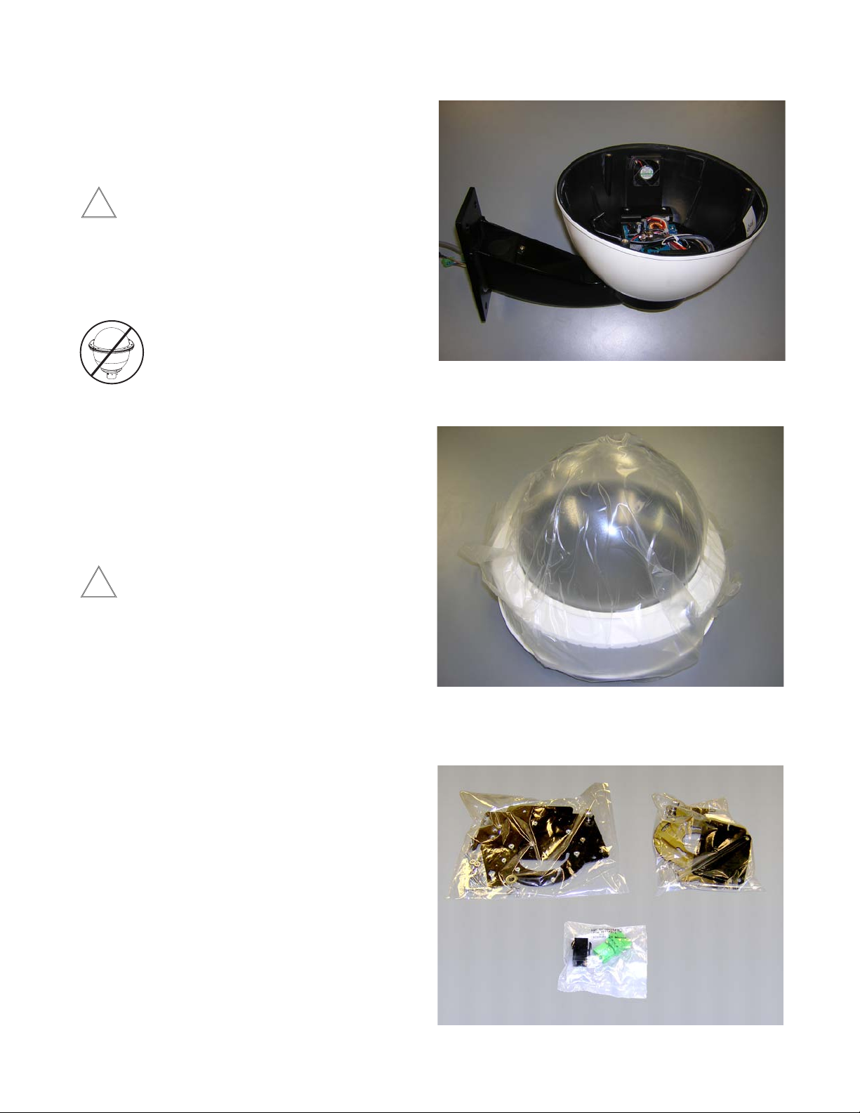
ASSEMBLING THE UNIT:
Remove content from all boxes. Contents should include:
Main Housing Assembly
Either with wall mount or pendant bracket
GENERAL INSTRUCTIONS:
Tools Required: .100" Flat Head Screwdriver
Phillips Head Screwdriver
Be sure the bracket is properly and securely mounted
to a supporting structure capable of rigidly holding
the weight of the entire unit.
CARE AND CLEANING OF DOMES:
All FDW75 and FDP75 units include an optically clear
polycarbonate dome. The dome is an optical device and
should be handled with extreme care. Leave protective lm
on dome until product is fully assembled and installed. Even
though the dome is virtually unbreakable, it can be easily
scratched.
Clean only with a clean cotton cloth and warm water.
DO NOT use a strong solvent or cleanser!
Dome Assembly - Clear or Tinted
Do not remove the protective lm until the product is
assembled and installed.
3 Packet Assemblies
- 3 -

INSTALLATION OF PTZ CAMERA
See model for specic instruction.
Listed on the following pages are the specic instructions
for each of the individual network cameras. See specic
instruction for the model that matches the unit you have.
INDEX OF CAMERAS
AXIS 213 5
AXIS 214 6
CANON VB-C10R 7
CANON VB-C50iR 8
CANON VC-C4R / VC-C50iR 9
ELMO PTC-200C 10
ELMO PTC-201 11
ELMO PTC-400C 12
ELMO PTC-401 13
JVC VN-C30U 14
PANASONIC BB-HCM381 / KX-HMC280 15
PIXORD 261 / 262 16
SONY SNCRZ30 17
SONY SNCRZ50 18
TOSHIBA IK-WB21A 19
- 4 -
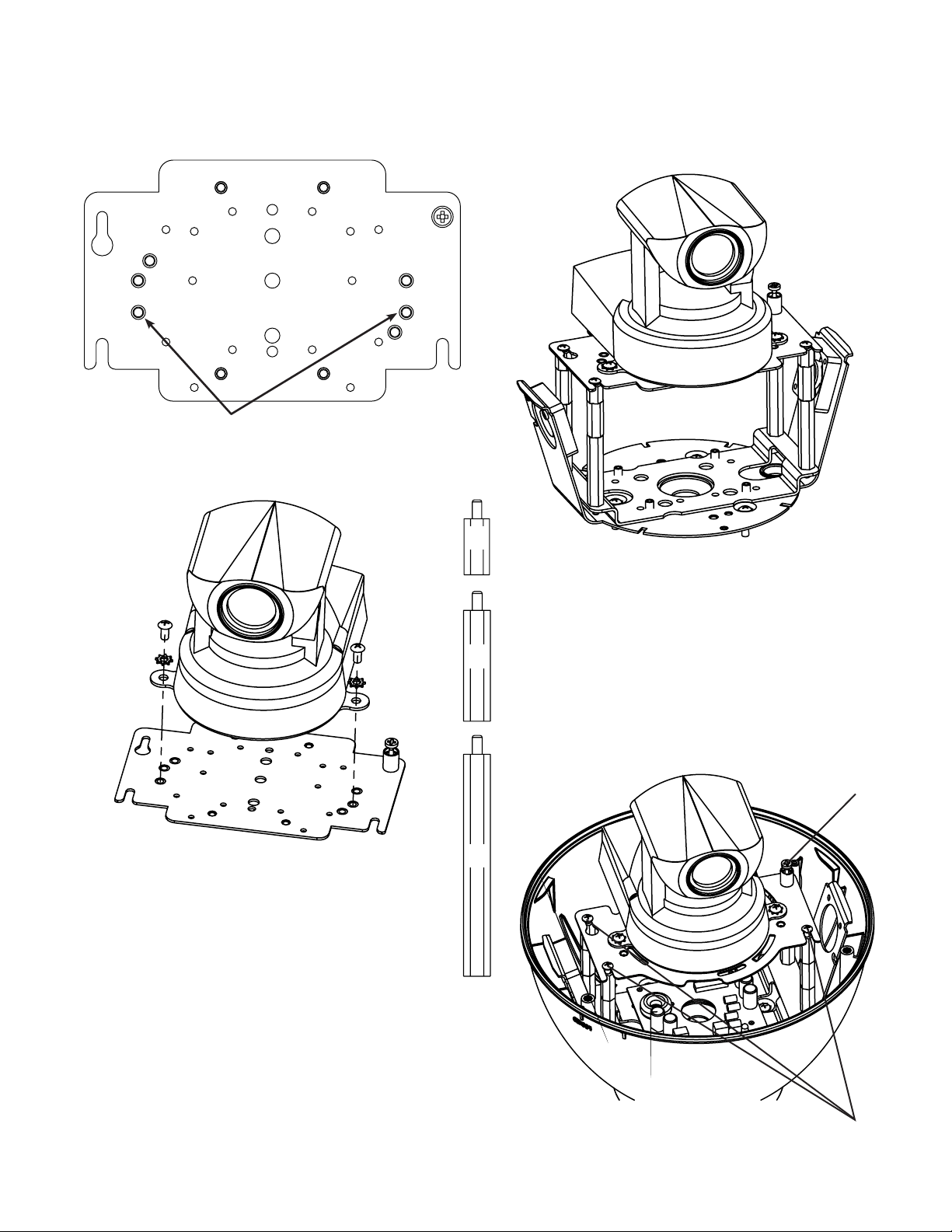
INSTALLING QUICK RELEASE BRACKETS
AXIS 213
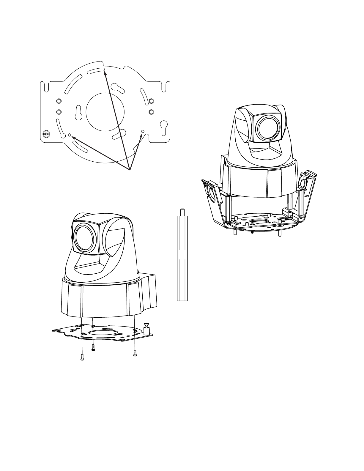
2539 Mounting Plate:
Attach camera using these (2) holes
1. Install the camera to the 2539 mounting plate using
(2) 10-32 screws and lockwashers provided.
2. The Axis 213 camera requires 3.5" of spacing for optimal
position within the housing. Use (4) 2" spacer(s), plus
(4) 1" spacer(s) and (4) ½" spacer(s) provided in the (2)
hardware packets.
½"
3. Place (3) 8 x 32 x s Phillips head screws on the top
of the spacer as shown above. Be sure to place the
screws so that they line up with the open slots on the
1"
mounting plate.
4. Slide the mounting plate with camera into position on
top of spacers. Secure 3 screws and captive fastener.
2"
Captive Screw
- 5 -
(3) screws
in housing
INSTALLING QUICK RELEASE BRACKETS
AXIS 214
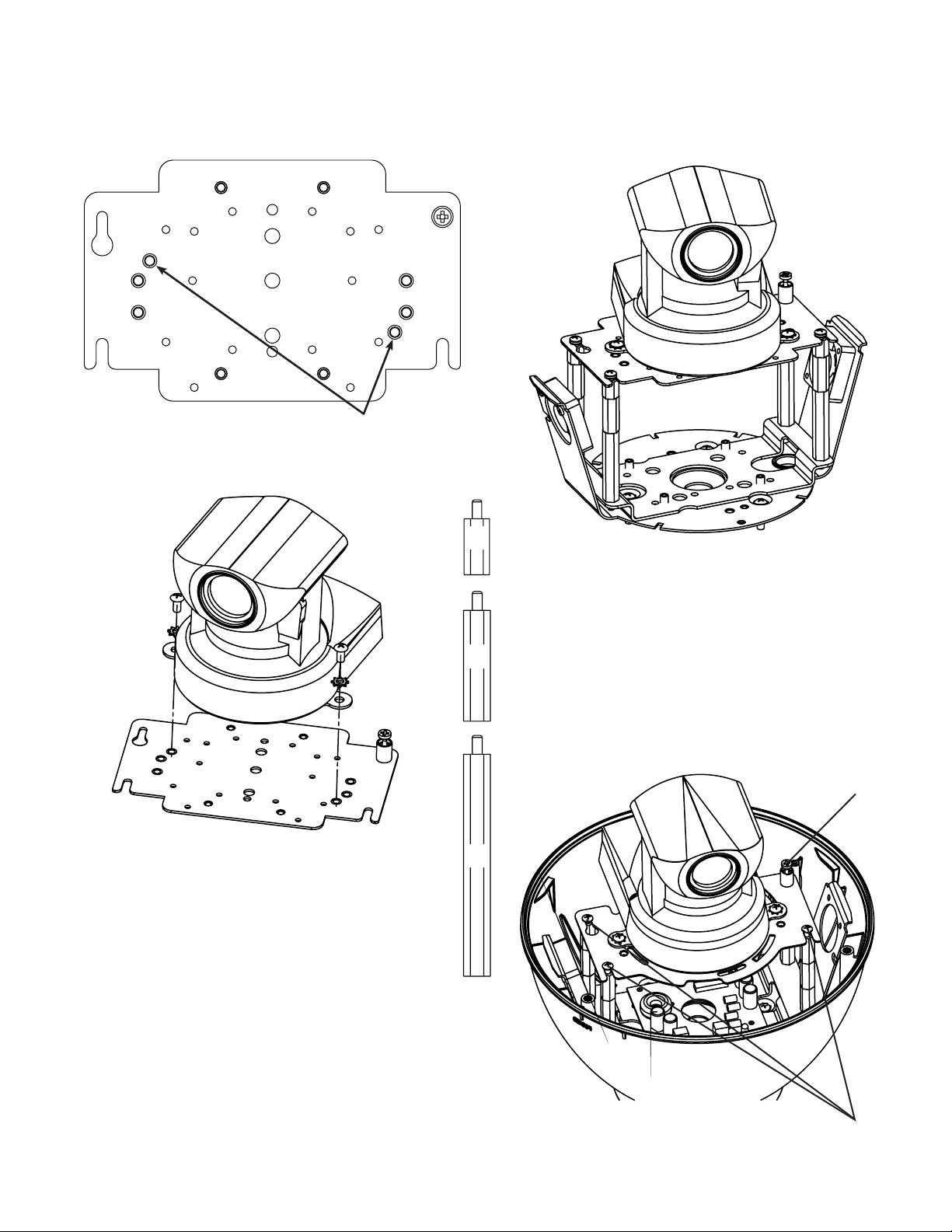
2685 Mounting Plate:
Attach camera using these (3) holes
1. Install the AXIS 214 camera to the 2685 mounting
plate using the (3) 3mm x 12mm bolt and lock washers
provided.
2. The AXIS 214 camera requires 2” of spacing for optimal
position within the housing. Use the 4 (2”) spacers
provided in the packet.
3. Place (3) 8 x 32 x s Phillips head screws on the top
2"
of the spacer as shown above. Be sure to place the
screws so that they line up with the open slots on the
mounting plate.
4. Slide the mounting plate with camera into position on
top of spacers. Secure 3 screws and captive fastener.
- 6 -

INSTALLING QUICK RELEASE BRACKETS
CANON VB-C10R
2539 Mounting Plate:
Attach camera using these (2) holes
1. Install the camera to the 2539 mounting plate using
(2) 10-32 screws and lockwashers provided.
2. The Canon VB-C10R camera requires 4" of spacing for
optimal position within the housing. Use (4) 2" spacer(s),
plus (4) 1" spacer(s) and (4) ½" spacer(s) provided in the
(2) hardware packets.
½"
3. Place (3) 8 x 32 x s Phillips head screws on the top
of the spacer as shown above. Be sure to place the
screws so that they line up with the open slots on the
1"
mounting plate.
4. Slide the mounting plate with camera into position on
top of spacers. Secure 3 screws and captive fastener.
2"
Captive Screw
- 7 -
(3) screws
in housing
INSTALLING QUICK RELEASE BRACKETS
CANON VB-C50iR
2539 Mounting Plate:
Attach camera using these (2) holes
1. Install the camera to the 2539 mounting plate using
(2) 10-32 screws and lockwashers provided.
2. The Canon VB-C50iR camera requires 3.5" of spacing for
optimal position within the housing. Use (4) 2" spacer(s),
plus (4) 1" spacer(s) and (4) ½" spacer(s) provided in the
(2) hardware packets.
½"
3. Place (3) 8 x 32 x s Phillips head screws on the top
of the spacer as shown above. Be sure to place the
screws so that they line up with the open slots on the
1"
mounting plate.
4. Slide the mounting plate with camera into position on
top of spacers. Secure 3 screws and captive fastener.
2"
Captive Screw
- 8 -
(3) screws
in housing
 Loading...