


Workshop Manual
NAVIGATOR
Copyright by
MVAGUSTA MOTORCYCLES S.p.A. Via G. Macchi , 144 (Schiranna) 21100 VARESE - ITALY
1st Edition
Printed in Italy
Print no. - 8A0095860
1

Introduction
This publication is intended for CAGIVA Workshops and is designed to help authorized personnel in service and repair operations. Familiarity with the specifications provided herein is a key factor in ensuring effective training of operators.
To make the manual easy to understand, the different paragraphs are identified by icons that point out the subjects being dealt with.
Notes having special meanings are marked with the following symbols:
Accident-prevention rules for the operator and other people working close by.
There is a possibility that the vehicle and/or its components may be damaged.
Further information on the operation being performed.
Tips
To avoid problems and obtain the best possible results, CAGIVA recommends observing the following general rules:
-Before carrying out any repairs, evaluate the customer’s report of the vehicle’s malfunction and ask any questions that may help clarify the nature of the problem.
-Clearly identify the causes of the malfunction. This manual provides the fundamentals of troubleshooting, which the operator will complete with his personal experience and the participation in the periodic training courses organized by CAGIVA.
-Make a rational plan of the repair so as to avoid wasting time in collecting spares, preparing tools, etc.
-Only perform the operations that are required to reach the part to be repaired. Helpful guidelines are provided in the disassembling and removing procedures described in this manual.
General repairing rules
1 Always replace gaskets, sealing rings and cotter pins with new ones.
2 When loosening or tightening nuts or screws, always begin with the largest, or with the one at the centre. Tighten with the prescribed torques using a crosswise pattern.
3 Always mark the parts and positions that might be exchanged when reassembling. 4 Use genuine CAGIVA spares, and lubricants of the recommended brands.
5 Use special tools as specified.
6 Consult the Technical Circulars, as they may contain updated information on adjusting and service procedures.
2
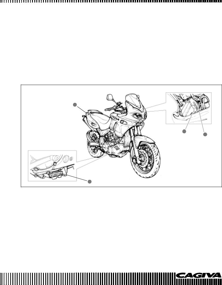
IDENTIFICATION DATA
The vehicle is identified by the following:
-Motorcycle serial number (1) on the right side of the head tube.
-Engine serial number (2) on the lower part of the right-hand crankcase half.
-Colour code on plate (3) inside the glove compartment under the saddle.
-Homologation data on the plate applied to the frame lower tube, next to the steering
head tube.
When ordering spares, always mention the motorcycle and engine serial numbers and the colour code.
3
1
4
2
3

Contents |
|
|
|
Section |
Page |
General information..................................................................... |
A |
5 |
Maintenance............................................................................................ |
B |
9 |
Injection - Air intake system ........................................................ |
C |
45 |
Engine ......................................................................................... |
D |
119 |
Suspensions and wheels ............................................................ |
E |
299 |
Brakes ...................................................................................................... |
F |
324 |
Electrical equipment .................................................................... |
G |
338 |
Engine cooling............................................................................. |
H |
376 |
Specific tooling ............................................................................ |
I |
390 |
Tightening torques....................................................................... |
L |
394 |
Index ......................................................................................................... |
M |
400 |
4

GENERAL INFORMATION
Section A
A.1

GENERAL INFORMATION
|
|
|
|
|
|
|
|
|
|
|
|
|
|
|
|
|
|
|
|
|
|
|
|
|
|
|
|
|
|
|
|
|
|
|
|
|
|
|
|
|
|
|
|
|
|
|
|
|
|
|
|
|
|
|
|
|
|
|
|
|
|
|
|
|
|
|
|
|
|
|
|
|
|
|
|
|
|
|
|
|
|
|
|
|
|
|
|
|
|
|
|
|
|
|
|
|
|
|
|
|
|
|
|
|
|
|
|
|
|
|
|
|
|
|
|
|
|
..........................................................Dimensions and weight |
A-3 |
||||||||||||||||||||||||||||||||||||||||||||||||||||||||||||||||||||||||||||||||||||||||||||||||||||||||||||||||||||
Engine unit ............................................................................. |
A-3 |
||||||||||||||||||||||||||||||||||||||||||||||||||||||||||||||||||||||||||||||||||||||||||||||||||||||||||||||||||||
Transmission unit ................................................................... |
A-3 |
||||||||||||||||||||||||||||||||||||||||||||||||||||||||||||||||||||||||||||||||||||||||||||||||||||||||||||||||||||
Frame ..................................................................................... |
A-4 |
||||||||||||||||||||||||||||||||||||||||||||||||||||||||||||||||||||||||||||||||||||||||||||||||||||||||||||||||||||
Front suspension .................................................................... |
A-4 |
||||||||||||||||||||||||||||||||||||||||||||||||||||||||||||||||||||||||||||||||||||||||||||||||||||||||||||||||||||
Rear suspension .................................................................... |
A-4 |
||||||||||||||||||||||||||||||||||||||||||||||||||||||||||||||||||||||||||||||||||||||||||||||||||||||||||||||||||||
Wheels and brakes ................................................................ |
A4 |
||||||||||||||||||||||||||||||||||||||||||||||||||||||||||||||||||||||||||||||||||||||||||||||||||||||||||||||||||||
Electrical system .................................................................... |
A-4 |
||||||||||||||||||||||||||||||||||||||||||||||||||||||||||||||||||||||||||||||||||||||||||||||||||||||||||||||||||||
Instrument panel .................................................................... |
A-4 |
||||||||||||||||||||||||||||||||||||||||||||||||||||||||||||||||||||||||||||||||||||||||||||||||||||||||||||||||||||
Fuel/oil/coolant/fork oil capacity ............................................. |
A-4 |
||||||||||||||||||||||||||||||||||||||||||||||||||||||||||||||||||||||||||||||||||||||||||||||||||||||||||||||||||||
A.2
GENERAL INFORMATION
DIMENSIONS AND WEIGHTS
NAVIGATOR
Overall length .......................................................................... |
2168 mm |
Overall width ........................................................................... |
790 mm |
Overall height .......................................................................... |
1290 mm |
Wheelbase .............................................................................. |
1530 mm |
Ground clearance.................................................................... |
180 mm |
Seat height .............................................................................. |
850 mm |
Dry weight ............................................................................... |
222 kg |
790
|
|
|
|
|
|
|
|
|
|
|
|
|
|
|
|
|
|
|
|
|
|
|
|
|
|
|
|
1290 |
|
|
|
|
|
|
|
|
|
|
|
|
|
|
|
|
|
|
|
|
|
|
|
|
|
|
|
|
|
|
|||||||||||||||||||||||||||||||||||||||||||||||||||||||||||||||||||||||
850 |
|
|
|
|
|
|
|
|
|
|
|
|
|
|
|
|
|
|
|
|
|
|
|
|
|
|
|
|
|
|
|
|
|
|
|
|
|
|
|
|
|
|
|
|
|
|
|
|
|
|
|
|
|
|
|
|
|
|
|
|
|
|
|
|
|
|
|
|
|
|
|
|
|
|
|
|
|
|
|
|
|
|
|
|
|
|
|
|
|
|
|
|
|
|
|
|
|
|
|
|
|
|
|||||||||||||||||||||||||||
|
|
|
|
|
|
|
|
|
|
|
|
|
|
|
|
|
|
|
|
|
|
|
|
|
|
|
|
180 |
|
|
|
|
|
|
|
|
|
|
|
|
|
|
|
|
|
|
|
|
|
|
|
|
|
|
|
|
|
|
|
|
|
|
|
|
|
|
|
|
|
|
|
|
|
|
|
|
|
|
|
|
|
|
|
|
|
|
|
|
|
||||||||||||||||||||||||||||||||||||||||
|
|
|
|
|
|
|
|
|
|
|
|
|
|
|
|
|
|
|
|
|
|
|
|
|
|
|
|
1530 |
|
|
|
|
|
|
|
|
|
|
|
|
|
|
|
|
|
|
|
|
|
|
|
|
|
|
|
|
|
|
|
|
|
|
|
|
|
|
|
|
|
|
|
|
|
|
|
|
|
|
|
|
|
|
|
|
|
|
|
|
|
|
|
|
|
|
|
|
|
|
|||||||||||||||||||||||||||||||
|
|
|
|
|
|
|
|
|
|
|
|
|
|
|
|
|
|
|
|
|
|
|
|
|
|
|
|
2168 |
|
|
|
|
|
|
|
|
|
|
|
|
|
|
|
|
|
|
|
|
|
|
|
|
|
|
|
|
|
|
|
|
|
|
|
|
|
|
|
|
|
|
|
|
|
|
|
|
|
|
|
|
|
|
|
|
|
|
|
|
|
|
|
|
|
|
|
|
|
|
|||||||||||||||||||||||||||||||
|
|
|
|
|
|
|
|
|
|
|
|
|
|
|
|
|
|
|
|
|
|
|
|
|
|
|
|
|
|
|
|
|
|
|
|
|
|
|
|
|
|
|
|
|
|
|
|
|
|
|
|
|
|
|
|
|
|
|
|
|
|
|
|
|
|
|
|
|
|
|
|
|
|
|
|
|
|
|
|
|
|
|
|
|
|
|
|
|
|
|
|
|
|
|
|
|
|
|
|
|
|
|
|
|
|
|
|
|
|
|
|
|
|
|
|
|
|
|
|
|
|
|
|
|
|
|
|
|
|
ENGINE UNIT |
|
|
|
|
|
|
|
|
|
|
|
|
|
|
|
|
|
|
|
|
|
|
|
|
|
|
|
|
|
|
|
|
|
|
|
|
|
|
|
|
|
|
|
|
|
|
|
|
|
|
|
|
|
|
|
|
|
|
|
|
|
|
|
|
|
|
|
|
|
|
|
|
|
|
|
|
|
|
|
|
|
|
|
|
|
|
|
|
|
|
|
|
|
|
|
|
|
|
|
|
|
|
|||||||||||||||||||||||||||
Type ............................................................................................ |
|
|
|
|
|
|
|
|
|
|
|
|
|
|
|
|
|
|
|
|
|
|
Liquid cooled, DOHC, TSCC four stroke |
|
|
|
|
|
|
|
|
|
|
|
|
|
|
|
|
|
|
|
|
|
|||||||||||||||||||||||||||||||||||||||||||||||||||||||||||||||||||||||||||||||||||||
Number of cylinders .................................................................... |
2 |
|
|
|
|
|
|
|
|
|
|
|
|
|
|
|
|
|
|
|
|
|
|
|
|
|
|
|
|
|
|
|
|
|
|
|
|
|
|
|
|
|
|
|
|
|
|
|
|
|
|
|
|
|
|
|
|
|
|
|
|
|
|
|
|
|
|
|
|
|
|
|
|
|
|
|
|
|
|
||||||||||||||||||||||||||||||||||||||||||||||||||
Bore ............................................................................................. |
|
|
|
|
|
|
|
|
|
|
|
|
|
|
|
|
|
|
|
|
|
|
98,0 mm |
|
|
|
|
|
|
|
|
|
|
|
|
|
|
|
|
|
|
|
|
|
|||||||||||||||||||||||||||||||||||||||||||||||||||||||||||||||||||||||||||||||||||||
Stroke .......................................................................................... |
|
|
|
|
|
|
|
|
|
|
|
|
|
|
|
|
|
|
|
|
|
|
66 mm |
|
|
|
|
|
|
|
|
|
|
|
|
|
|
|
|
|
|
|
|
|
|||||||||||||||||||||||||||||||||||||||||||||||||||||||||||||||||||||||||||||||||||||
Displacement .............................................................................. |
|
|
|
|
|
|
|
|
|
|
|
|
|
|
|
|
|
|
|
|
|
|
996 cm3 |
|
|
|
|
|
|
|
|
|
|
|
|
|
|
|
|
|
|
|
|
|
|||||||||||||||||||||||||||||||||||||||||||||||||||||||||||||||||||||||||||||||||||||
Compression ratio ....................................................................... |
11.3 : 1 |
|
|
|
|
|
|
|
|
|
|
|
|
|
|
|
|
|
|
|
|
|
|
|
|
|
|
|
|
|
|
|
|
|
|
|
|
|
|
|
|
|
|
|
|
|
|
|
|
|
|
|
|
|
|
|
|
|
|
|
|
|
|
|
|
|
|
|
|
|
|
|
|
||||||||||||||||||||||||||||||||||||||||||||||||||||||||
Fuel feed system ......................................................................... |
|
|
|
|
|
|
|
|
|
|
|
|
|
|
|
|
|
|
|
|
|
|
Injection |
|
|
|
|
|
|
|
|
|
|
|
|
|
|
|
|
|
|
|
|
|
|||||||||||||||||||||||||||||||||||||||||||||||||||||||||||||||||||||||||||||||||||||
Air filter ........................................................................................ |
|
|
|
|
|
|
|
|
|
|
|
|
|
|
|
|
|
|
|
|
|
|
Non woven synthetic material |
|
|
|
|
|
|
|
|
|
|
|
|
|
|
|
|
|
|
|
|
|
|||||||||||||||||||||||||||||||||||||||||||||||||||||||||||||||||||||||||||||||||||||
Starter system ............................................................................. |
|
|
|
|
|
|
|
|
|
|
|
|
|
|
|
|
|
|
|
|
|
|
Electric |
|
|
|
|
|
|
|
|
|
|
|
|
|
|
|
|
|
|
|
|
|
|||||||||||||||||||||||||||||||||||||||||||||||||||||||||||||||||||||||||||||||||||||
Lubrication system ...................................................................... |
|
|
|
|
|
|
|
|
|
|
|
|
|
|
|
|
|
|
|
|
|
|
Wet sump |
|
|
|
|
|
|
|
|
|
|
|
|
|
|
|
|
|
|
|
|
|
|||||||||||||||||||||||||||||||||||||||||||||||||||||||||||||||||||||||||||||||||||||
TRANSMISSION UNIT |
|
|
|
|
|
|
|
|
|
|
|
|
|
|
|
|
|
|
|
|
|
|
|
|
|
|
|
|
|
|
|
|
|
|
|
|
|
|
|
|
|
|
|
|
|
|
|
|
|
|
|
|
|
|
|
|
|
|
|
|
|
|
|
|
|
|
|
|
|
|
|
|
|
|
|
|
|
|
|
|
|
|
|
|
|
|
|
|
|
|
|
|
|
|
|
|
|
|
|
|
|
|
|||||||||||||||||||||||||||
Clutch .......................................................................................... |
|
|
|
|
|
|
|
|
|
|
|
|
|
|
|
|
|
|
|
|
|
|
Wet multi-plate type |
|
|
|
|
|
|
|
|
|
|
|
|
|
|
|
|
|
|
|
|
|
|||||||||||||||||||||||||||||||||||||||||||||||||||||||||||||||||||||||||||||||||||||
Gearbox ...................................................................................... |
|
|
|
|
|
|
|
|
|
|
|
|
|
|
|
|
|
|
|
|
|
|
6 speed constant mesh |
|
|
|
|
|
|
|
|
|
|
|
|
|
|
|
|
|
|
|
|
|
|||||||||||||||||||||||||||||||||||||||||||||||||||||||||||||||||||||||||||||||||||||
Gear change ............................................................................... |
|
|
|
|
|
|
|
|
|
|
|
|
|
|
|
|
|
|
|
|
|
|
1 down, 5 up |
|
|
|
|
|
|
|
|
|
|
|
|
|
|
|
|
|
|
|
|
|
|||||||||||||||||||||||||||||||||||||||||||||||||||||||||||||||||||||||||||||||||||||
Primary reduction ........................................................................ |
1.838 (57/31) |
|
|
|
|
|
|
|
|
|
|
|
|
|
|
|
|
|
|
|
|
|
|
|
|
|
|
|
|
|
|
|
|
|
|
|
|
|
|
|
|
|
|
|
|
|
|
|
|
|
|
|
|
|
|
|
|
|
|
|
|
|
|
|
|||||||||||||||||||||||||||||||||||||||||||||||||||||||||||||||||
Final reduction ............................................................................. |
2.562 (41/16) |
|
|
|
|
|
|
|
|
|
|
|
|
|
|
|
|
|
|
|
|
|
|
|
|
|
|
|
|
|
|
|
|
|
|
|
|
|
|
|
|
|
|
|
|
|
|
|
|
|
|
|
|
|
|
|
|
|
|
|
|
|
|
|
|||||||||||||||||||||||||||||||||||||||||||||||||||||||||||||||||
Gear ratios, 1a ............................................................................ |
2.666 (32/12) |
|
|
|
|
|
|
|
|
|
|
|
|
|
|
|
|
|
|
|
|
|
|
|
|
|
|
|
|
|
|
|
|
|
|
|
|
|
|
|
|
|
|
|
|
|
|
|
|
|
|
|
|
|
|
|
|
|
|
|
|
|
|
|
|||||||||||||||||||||||||||||||||||||||||||||||||||||||||||||||||
|
|
|
|
|
|
|
|
|
|
|
|
|
|
|
2a .................................................................. |
1.933 (29/15) |
|
|
|
|
|
|
|
|
|
|
|
|
|
|
|
|
|
|
|
|
|
|
|
|
|
|
|
|
|
|
|
|
|
|
|
|
|
|
|
|
|
|
|
|
|
|
|
|
|
|
|
|
|
|
|
|
|
|
|
|
|
|
|
||||||||||||||||||||||||||||||||||||||||||||||||||
|
|
|
|
|
|
|
|
|
|
|
|
|
|
|
3a .................................................................. |
1.500 (27/18) |
|
|
|
|
|
|
|
|
|
|
|
|
|
|
|
|
|
|
|
|
|
|
|
|
|
|
|
|
|
|
|
|
|
|
|
|
|
|
|
|
|
|
|
|
|
|
|
|
|
|
|
|
|
|
|
|
|
|
|
|
|
|
|
||||||||||||||||||||||||||||||||||||||||||||||||||
|
|
|
|
|
|
|
|
|
|
|
|
|
|
|
4a .................................................................. |
1.227 (27/22) |
|
|
|
|
|
|
|
|
|
|
|
|
|
|
|
|
|
|
|
|
|
|
|
|
|
|
|
|
|
|
|
|
|
|
|
|
|
|
|
|
|
|
|
|
|
|
|
|
|
|
|
|
|
|
|
|
|
|
|
|
|
|
|
||||||||||||||||||||||||||||||||||||||||||||||||||
|
|
|
|
|
|
|
|
|
|
|
|
|
|
|
5a .................................................................. |
1.086 (25/23) |
|
|
|
|
|
|
|
|
|
|
|
|
|
|
|
|
|
|
|
|
|
|
|
|
|
|
|
|
|
|
|
|
|
|
|
|
|
|
|
|
|
|
|
|
|
|
|
|
|
|
|
|
|
|
|
|
|
|
|
|
|
|
|
||||||||||||||||||||||||||||||||||||||||||||||||||
|
|
|
|
|
|
|
|
|
|
|
|
|
|
|
6a .................................................................. |
1.000 (24/24) |
|
|
|
|
|
|
|
|
|
|
|
|
|
|
|
|
|
|
|
|
|
|
|
|
|
|
|
|
|
|
|
|
|
|
|
|
|
|
|
|
|
|
|
|
|
|
|
|
|
|
|
|
|
|
|
|
|
|
|
|
|
|
|
||||||||||||||||||||||||||||||||||||||||||||||||||
Transmission chain ..................................................................... |
|
|
|
|
|
|
|
|
|
|
|
|
|
|
|
|
|
|
|
|
|
|
5/8” x 5.16” |
|
|
|
|
|
|
|
|
|
|
|
|
|
|
|
|
|
|
|
|
|
|||||||||||||||||||||||||||||||||||||||||||||||||||||||||||||||||||||||||||||||||||||
|
|
|
|
|
|
|
|
|
|
|
|
|
|
|
|
|
|
|
|
|
|
|
|
|
|
|
|
|
|
|
|
|
|
|
|
|
|
|
|
|
|
|
|
|
|
|
|
|
|
|
|
|
|
|
|
|
|
|
|
|
|
|
|
|
|
|
|
|
|
|
|
|
|
|
|
|
|
|
|
|
|
|
|
|
|
|
|
|
|
|
|
|
|
|
|
|
|
|
|
|
|
|
|
|
|
|
|
|
|
|
|
|
|
|
|
|
|
|
|
|
|
|
|
|
|
|
|
|
|
|
|
|
|
|
|
|
|
|
|
|
|
|
|
|
|
|
|
|
|
|
|
|
|
|
|
|
|
|
|
|
|
|
|
|
|
|
|
|
|
|
|
|
|
|
|
|
|
|
|
|
|
|
|
|
|
|
|
|
|
|
|
|
|
|
|
|
|
|
|
|
|
|
|
|
|
|
|
|
|
|
|
|
|
|
|
|
|
|
|
|
|
|
|
|
|
|
|
|
|
|
|
|
|
|
|
|
|
|
|
|
|
|
|
|
|
|
|
|
|
|
|
|
|
|
|
|
|
|
|
|
|
|
|
|
|
|
|
|
|
|
|
|
|
|
|
|
|
|
|
|
|
|
|
|
|
|
|
|
|
|
|
|
|
|
|
|
|
|
|
|
|
|
|
|
|
|
|
|
|
|
|
|
|
|
|
|
|
|
|
|
|
|
|
|
|
|
|
|
|
|
|
|
|
|
|
|
|
|
|
|
|
|
|
|
|
|
|
|
|
|
|
|
|
|
|
|
|
|
|
|
|
|
|
|
|
|
|
|
|
|
|
|
|
|
|
|
|
|
|
|
|
|
|
|
|
|
|
|
|
A.3

GENERAL INFORMATION
FRAME
Type ........................................................................................... |
Rectangular and square box section tubular framework |
|
in highly resistant steel with box-type strengthening |
|
supports at the fork fulcrum attachment. |
FRONT SUSPENSION
Type ........................................................................................... |
Conventional advanced pivot hydraulic telescopic fork |
|
with 45 mm diameter tubes. Telescopic movement 150 mm. |
Steering angle ............................................................................ |
32° (left and right) |
Steering head angle ................................................................... |
25° |
Trail ............................................................................................ |
110 mm |
REAR SUSPENSION
Type ............................................................................................ |
Single hydraulic shock absorber progressively damped |
|
with external pre-load adjustment of the spring and |
|
extension of the hydraulic braking effect. Wheel travel 160 mm. |
WHEELS AND BRAKES
Front brake ................................................................................. |
Twin disc |
|
Rear brake ................................................................................. |
Single disc |
|
Front tyre .................................................................................... |
Metzeler ME Z4 |
C – 110/80 – 18” |
Rear tyre .................................................................................... |
Metzeler ME Z4 |
– 150/70 – 17” |
ELECTRICAL SYSTEM
Transistorised electronic ignition |
|
|
Ignition phase ............................................................................. |
3° before T.D.C. at 1300 rpm |
|
Spark plugs ................................................................................ |
NGK CR8EK or DENSO U24ETR |
|
Battery ........................................................................................ |
12v |
10Ah |
Generator ................................................................................... |
Three phase AC generator |
|
Fuses ......................................................................................... |
30/30/15/15/15/10/10A |
|
Headlight unit ............................................................................. |
Main beam: condenser halogen bulb H1 12v-55w |
|
|
Dipped beam: polyellipsoidal bulb H3 12v-55w |
|
Sidelight ..................................................................................... |
12v |
5w |
Direction indicators ..................................................................... |
12v |
10w |
Number plate light ...................................................................... |
12v |
5w |
Brake/tail light............................................................................. |
12v |
21/5w |
INSTRUMENT PANEL
Instrument bulb .......................................................................... |
12V |
1.2W |
Warning lights ............................................................................ |
12V |
2W |
FUEL/OIL/COOLANT/FORK OIL CAPACITY
Fuel tank ..................................................................................... |
20 L |
Engine oil: oil change .................................................................. |
3100 ml |
oil change with filter ................................................ |
3300 ml |
overhaul .................................................................. |
3600 ml |
Engine coolant ............................................................................ |
2000 ml |
Fork oil (each tube) ..................................................................... |
680 ml |
A.4

MAINTENANCE
Section B
B.1

MAINTENANCE
|
|
|
|
|
|
|
|
|
|
|
|
|
|
|
|
|
|
|
|
|
|
|
|
|
|
|
|
|
|
|
|
|
|
|
|
|
|
|
|
|
|
|
|
|
|
|
|
|
|
|
|
|
|
|
|
|
|
|
|
|
|
|
|
|
|
|
|
|
|
|
|
|
|
|
|
|
|
|
|
|
|
|
|
|
|
|
|
|
|
|
|
|
|
|
|
|
|
|
|
|
|
|
|
|
|
|
|
|
|
|
|
|
|
|
|
|
|
.........................................................Maintenance and tuning |
B-4 |
||||||||||||||||||||||||||||||||||||||||||||||||||||||||||||||||||||||||||||||||||||||||||||||||||||||||||||||||||||
Compression check................................................................ |
B-23 |
||||||||||||||||||||||||||||||||||||||||||||||||||||||||||||||||||||||||||||||||||||||||||||||||||||||||||||||||||||
Oil pressure check ................................................................. |
B-24 |
||||||||||||||||||||||||||||||||||||||||||||||||||||||||||||||||||||||||||||||||||||||||||||||||||||||||||||||||||||
Technical data ........................................................................ |
B-25 |
||||||||||||||||||||||||||||||||||||||||||||||||||||||||||||||||||||||||||||||||||||||||||||||||||||||||||||||||||||
B.2
MAINTENANCE
|
|
|
|
|
|
|
|
|
|
|
|
|
|
|
|
|
|
|
|
|
|
|
|
|
|
|
|
|
|
|
|
|
|
|
|
|
|
|
|
|
|
|
|
|
|
|
|
|
|
|
|
|
|
|
|
|
|
|
|
|
|
|
|
|
|
|
|
|
|
|
|
|
|
|
|
|
|
|
|
|
|
|
|
|
|
|
|
|
|
|
|
|
|
|
|
|
|
|
|
|
|
|
|
|
|
|
|
|
|
|
|
|
|
|
|
|
|
|
|
|
|
|
|
|
|
|
|
|
|
|
|
|
|
|
|
|
|
|
|
|
|
|
|
|
|
|
|
|
|
|
|
|
|
|
|
|
|
|
|
|
|
|
|
|
|
|
|
|
|
|
|
|
|
|
|
|
|
|
|
|
|
|
|
|
|
|
|
|
|
|
|
|
|
|
|
|
|
|
|
|
|
|
|
|
|
|
|
|
|
|
|
|
|
|
|
|
|
|
|
|
|
|
|
|
|
|
|
|
|
|
|
|
|
|
|
|
|
|
|
|
|
|
|
|
|
|
|
|
|
|
|
|
|
|
Check ■ |
Substitution |
● |
|
|
|
|
|
|
|
|
|
|
|
|
|
|
|
|
|
|
|
|
|
|
|
|
First |
|
|
|
|
Every |
|
|
|
|
|
|
|
Every |
|
|
|
|
|
Every |
|
|
|
|
|
Every |
|
|
|
|
Every |
|
|||||||||||||||||||||||||||||||||||||||||||||||||||||||||||||||||||
|
|
|
|
|
|
|
|
|
|
|
|
|
|
|
|
|
|
|
|
|
|
|
|
|
|
|
|
|
|
|
|
|
|
|
|
|
|
|
|
|
|
|
|
1000 km |
|
|
|
1000 km |
|
|
|
|
|
6000 km |
|
|
|
12000 km |
|
|
20000 km |
|
24000 km |
|
||||||||||||||||||||||||||||||||||||||||||||||||||||||||||||||
|
|
|
|
|
|
|
|
|
|
|
|
|
|
|
|
|
|
|
|
|
|
|
|
|
|
|
|
|
|
|
|
|
|
|
|
|
|
|
|
|
|
|
|
|
|
|
|
|
|
|
|
|
|
|
|
|
|
|
|
|
|
|
|
|
|
|
|
|
|
|
|
|
|
|
|
|
|
|
|
|
|
|
|
|
|
|
|
|
|
|
|
|
|
|
|
|
|
|
|
|
|
|
|
|
|
|
|
|
|
|
|
|
|
|
|
|
|
|
|
|
|
|
||||
|
Engine oil |
|
|
|
|
|
|
|
|
|
|
|
|
|
|
Check level |
|
|
|
|
|
|
|
|
|
|
|
|
|
|
|
■ |
|
|
|
|
|
|
|
|
|
|
|
|
|
|
|
|
|
|
|
|
|
|
|
|
|
|
|
|
|
|
|
|
|
|
|
|
|
|
|
|
|
|
|
|
|
|
|
|
|
|
|
|
|
|
|
|
|
|
|
|
|
|
|
|
|
|
||||||||||||||||||||||||||||
|
|
|
|
|
|
|
|
|
|
|
|
|
|
|
|
|
|
|
|
|
|
|
|
|
|
|
|
|
|
|
|
|
|
|
|
|
|
|
|
|
|
|
|
|
|
|
|
|
|
|
|
|
|
|
|
|
|
|
|
|
|
|
|
|
|
|
|
|
|
|
|
|
|
|
|
|
|
|
|
|
|
|
|
|
|
|
|
|
|
|
|
|
|
|
|
|
|
|
|
|
|
|
|
|
|
|
|
|
|
|
|
|
|
|
|
|
|
|||||||||
|
Engine oil |
|
|
|
|
|
|
|
|
|
|
|
|
|
|
Substitute |
|
|
|
|
|
|
● |
|
|
|
|
|
|
|
|
|
|
|
|
|
|
|
|
|
|
|
|
● |
|
|
|
|
|
|
|
|
|
|
|
|
|
|
|
|
|
|
|
|
|
|
|
|
|
|
|
|
|
|
|
|
|
|
|
|
|
|
|
|
|
|
|
|
|
|
|
|||||||||||||||||||||||||||||||||||
|
|
|
|
|
|
|
|
|
|
|
|
|
|
|
|
|
|
|
|
|
|
|
|
|
|
|
|
|
|
|
|
|
|
|
|
|
|
|
|
|
|
|
|
|
|
|
|
|
|
|
|
|
|
|
|
|
|
|
|
|
|
|
|
|
|
|
|
|
|
|
|
|
|
|
|
|
|
|
|
|
|
|
|
|
|
|
|
|
|
|
|
|
|
|
|
|
|
|
|
|
|
|
|
|
|
|
|
|
|
|
|
|
|
|
|
|
|
|
|
|||||||
|
Engine oil filter |
|
|
|
|
|
|
Substitute |
|
|
|
|
|
|
● |
|
|
|
|
|
|
|
|
|
|
|
|
|
|
|
|
|
|
|
|
|
|
|
|
|
|
|
|
|
|
|
|
|
|
|
|
|
|
● |
|
|
|
|
|
|
|
|
|
|
|
|
|
|
|
|
|
|
|
|
|
|
|
|
|
|
|
|
|
|
|
|||||||||||||||||||||||||||||||||||||||||
|
|
|
|
|
|
|
|
|
|
|
|
|
|
|
|
|
|
|
|
|
|
|
|
|
|
|
|
|
|
|
|
|
|
|
|
|
|
|
|
|
|
|
|
|
|
|
|
|
|
|
|
|
|
|
|
|
|
|
|
|
|
|
|
|
|
|
|
|
|
|
|
|
|
|
|
|
|
|
|
|
|
|
|
|
|
|
|
|
|
|
|
|
|
|
|
|
|
|
|
|
|
|
|
|
|
|
|
|
|
|
|
|
|
|
|
|
|
|
|
|
|
|
||||
|
Coolant |
|
|
|
|
|
|
|
|
|
|
|
|
|
|
Check level |
|
|
|
|
|
|
■ |
|
|
|
|
|
■ |
|
|
|
|
|
|
|
|
|
|
|
|
|
|
|
|
|
|
|
|
|
|
|
|
|
|
|
|
|
|
|
|
|
|
|
|
|
|
|
|
|
|
|
|
|
|
|
|
|
|
|
|
|
|
|
|
|
|
|
|
|
|
|
|
|
|
|||||||||||||||||||||||||||||||
|
|
|
|
|
|
|
|
|
|
|
|
|
|
|
|
|
|
|
|
|
|
|
|
|
|
|
|
|
|
|
|
|
|
|
|
|
|
|
|
|
|
|
|
|
|
|
|
|
|
|
|
|
|
|
|
|
|
|
|
|
|
|
|
|
|
|
|
|
|
|
|
|
|
|
|
|
|
|
|
|
|
|
|
|
|
|
|
|
|
|
|
|
|
|
|
|
|
|
|
|
|
|
|
|
|
|
|
|
|
|
|
|||||||||||||||
|
Coolant |
|
|
|
|
|
|
|
|
|
|
|
|
|
|
Substitute |
|
|
|
|
|
|
|
|
|
|
|
|
|
|
|
|
|
|
|
|
|
|
|
|
Every 2 years |
|
|
|
|
|
|
|
|
|
|
|
|
|
|
|
|
|
|
|
|
|
|
|
|
|
|
|
|
|
|
|
|
|
|
|
|
|
|
|
|
|
|
|
|
|
|
|
||||||||||||||||||||||||||||||||||||||
|
|
|
|
|
|
|
|
|
|
|
|
|
|
|
|
|
|
|
|
|
|
|
|
|
|
|
|
|
|
|
|
|
|
|
|
|
|
|
|
|
|
|
|
|
|
|
|
|
|
|
|
|
|
|
|
|
|
|
|
|
|
|
|
|
|
|
|
|
|
|
|
|
|
|
|
|
|
|
|
|
|
|
|
|
|
|
|
|
|
|
|
|
|
|
|
|
|
|
|
|
|
|
|
|
|
|
|
|
|
|
|
|
|
|
|
|
|
|
|
|||||||
|
Valve tappet clearance adjustment Check/adjust |
|
|
|
|
|
|
|
|
|
|
|
|
|
|
|
|
|
|
|
|
|
|
|
|
|
|
|
|
|
|
|
|
|
|
|
|
|
|
|
|
|
|
|
|
|
|
|
|
|
|
|
|
|
|
|
|
|
|
|
|
|
|
|
|
|
|
|
|
|
|
|
|
|
|
|
|
|
|
■ |
|
|||||||||||||||||||||||||||||||||||||||||||||
|
|
|
|
|
|
|
|
|
|
|
|
|
|
|
|
|
|
|
|
|
|
|
|
|
|
|
|
|
|
|
|
|
|
|
|
|
|
|
|
|
|
|
|
|
|
|
|
|
|
|
|
|
|
|
|
|
|
|
|
|
|
|
|
|
|
|
|
|
|
|
|
|
|
|
|
|
|
|
|
|
|
|
|
|
|
|
|
|
|
|
|
|
|
|
|
|
|
|
|
|
|
|
|
|
|
|
|
|
|
|
|
|
|
|
|
|
|
|
|
|||||||
|
Timing chain tension |
|
|
|
|
|
|
Check/adjust |
|
|
|
|
|
|
■ |
|
|
|
|
|
|
|
|
|
|
|
|
|
|
|
|
|
|
|
|
|
|
|
|
|
|
|
|
|
|
|
|
|
|
|
|
|
|
|
|
|
|
|
|
|
|
|
|
|
|
|
|
|
|
|
|
|
|
|
|
|
|
|
|
|
|
|
|
■ |
|
|||||||||||||||||||||||||||||||||||||||||
|
|
|
|
|
|
|
|
|
|
|
|
|
|
|
|
|
|
|
|
|
|
|
|
|
|
|
|
|
|
|
|
|
|
|
|
|
|
|
|
|
|
|
|
|
|
|
|
|
|
|
|
|
|
|
|
|
|
|
|
|
|
|
|
|
|
|
|
|
|
|
|
|
|
|
|
|
|
|
|
|
|
|
|
|
|
|
|
|
|
|
|
|
|
|
|
|
|
|
|
|
|
|
|
|
|
|
|
|
|
|
|
|
|
|
|
|
|
|
|
|||||||
|
Synchronisation butterfly valves |
|
|
Check/adjust |
|
|
|
|
|
|
|
|
|
|
|
|
|
|
|
|
|
|
|
|
|
|
|
|
|
|
|
|
|
|
|
|
|
|
|
|
|
|
|
|
|
|
|
|
|
|
|
|
■ |
|
|
|
|
|
|
|
|
|
|
|
|
|
|
|
|
|
|
|
|
|
|
|
|
|
|
|
|
|
|
|
||||||||||||||||||||||||||||||||||||||||||
|
|
|
|
|
|
|
|
|
|
|
|
|
|
|
|
|
|
|
|
|
|
|
|
|
|
|
|
|
|
|
|
|
|
|
|
|
|
|
|
|
|
|
|
|
|
|
|
|
|
|
|
|
|
|
|
|
|
|
|
|
|
|
|
|
|
|
|
|
|
|
|
|
|
|
|
|
|
|
|
|
|
|
|
|
|
|
|
|
|
|
|
|
|
|
|
|
|
|
|
|
|
|
|
|
|
|
|
|
|
|
||||||||||||||||
|
Spark plugs |
|
|
|
|
|
|
|
|
|
|
|
|
|
|
Check/substitute |
|
|
|
|
|
|
■ |
|
|
|
|
|
|
|
|
|
|
|
|
|
|
|
|
|
|
|
|
■ |
|
|
|
|
|
|
|
|
● |
|
|
|
|
|
|
|
|
|
|
|
|
|
|
|
|
|
|
|
|
|
|
|
|
|
|
|
|
|
|
|
||||||||||||||||||||||||||||||||||||||||||
|
|
|
|
|
|
|
|
|
|
|
|
|
|
|
|
|
|
|
|
|
|
|
|
|
|
|
|
|
|
|
|
|
|
|
|
|
|
|
|
|
|
|
|
|
|
|
|
|
|
|
|
|
|
|
|
|
|
|
|
|
|
|
|
|
|
|
|
|
|
|
|
|
|
|
|
|
|
|
|
|
|
|
|
|
|
|
|
|
|
|
|
|
|
|
|
|
|
|
|
|
|
|
|
|
|
|
|
|
|
|
|
|
|
|
|
|
|
|
|
|||||||
|
Fuel filter |
|
|
|
|
|
|
|
|
|
|
|
|
|
|
Substitute |
|
|
|
|
|
|
|
|
|
|
|
|
|
|
|
|
|
|
|
|
|
|
|
|
|
|
|
|
|
|
|
|
|
|
|
|
|
|
|
|
|
|
|
|
|
|
|
|
● |
|
|
|
|
|
|
|
|
|
|
|
|
|
|
|
|
|
|
|
|
|
|
|
|
|
|
|
|
|
|
|
||||||||||||||||||||||||||||||
|
|
|
|
|
|
|
|
|
|
|
|
|
|
|
|
|
|
|
|
|
|
|
|
|
|
|
|
|
|
|
|
|
|
|
|
|
|
|
|
|
|
|
|
|
|
|
|
|
|
|
|
|
|
|
|
|
|
|
|
|
|
|
|
|
|
|
|
|
|
|
|
|
|
|
|
|
|
|
|
|
|
|
|
|
|
|
|
|
|
|
|
|
|
|
|
|
|
|
|
|
|
|
|
|
|
|
|
|
|
|
||||||||||||||||
|
Air filter |
|
|
|
|
|
|
|
|
|
|
|
|
|
|
Check/substitute |
|
|
|
|
|
|
|
|
|
|
|
|
|
|
|
|
|
|
|
|
|
|
|
|
|
|
|
|
|
|
■ |
|
|
|
|
|
|
|
|
● |
|
|
|
|
|
|
|
|
|
|
|
|
|
|
|
|
|
|
|
|
|
|
|
|
|
|
|
|
|
|
|
|||||||||||||||||||||||||||||||||||||||
|
|
|
|
|
|
|
|
|
|
|
|
|
|
|
|
|
|
|
|
|
|
|
|
|
|
|
|
|
|
|
|
|
|
|
|
|
|
|
|
|
|
|
|
|
|
|
|
|
|
|
|
|
|
|
|
|
|
|
|
|
|
|
|
|
|
|
|
|
|
|
|
|
|
|
|
|
|
|
|
|
|
|
|
|
|
|
|
|
|
|
|
|
|
|
|
|
|
|
|
|
|
|
|
|
|
|
|
|
|
|
|
|
|
|
|
|
|
|||||||||
|
Fuel feed system |
|
|
|
|
|
|
Check |
|
|
|
|
|
|
|
|
|
|
|
|
|
|
|
|
|
|
|
|
|
|
|
|
|
|
|
|
|
|
■ |
|
|
|
|
|
|
|
|
|
|
|
|
|
|
|
|
|
|
|
|
|
|
|
|
|
|
|
|
|
|
|
|
|
|
|
|
|
|
|
|
|
|
|
|
|
|
|
||||||||||||||||||||||||||||||||||||||||
|
|
|
|
|
|
|
|
|
|
|
|
|
|
|
|
|
|
|
|
|
|
|
|
|
|
|
|
|
|
|
|
|
|
|
|
|
|
|
|
|
|
|
|
|
|
|
|
|
|
|
|
|
|
|
|
|
|
|
|
|
|
|
|
|
|
|
|
|
|
|
|
|
|
|
|
|
|
|
|
|
|
|
|
|
|
|
|
|
|
|
|
|
|
|
|
|
|
|
|
|
|
|
|
|
|
|
|
|
|
|
|
|
|
|
|
|
|
|
|
|
|
|
||||
|
Brake fluid |
|
|
|
|
|
|
|
|
|
|
|
|
|
|
Check level |
|
|
|
|
|
|
■ |
|
|
|
|
|
■ |
|
|
|
|
|
|
|
|
|
|
|
|
|
|
|
|
|
|
|
|
|
|
|
|
|
|
|
|
|
|
|
|
|
|
|
|
|
|
|
|
|
|
|
|
|
|
|
|
|
|
|
|
|
|
|
|
|
|
|
|
|
|
|
|
|
|
|||||||||||||||||||||||||||||||
|
|
|
|
|
|
|
|
|
|
|
|
|
|
|
|
|
|
|
|
|
|
|
|
|
|
|
|
|
|
|
|
|
|
|
|
|
|
|
|
|
|
|
|
|
|
|
|
|
|
|
|
|
|
|
|
|
|
|
|
|
|
|
|
|
|
|
|
|
|
|
|
|
|
|
|
|
|
|
|
|
|
|
|
|
|
|
|
|
|
|
|
|
|
|
|
|
|
|
|
|
|
|
|
|
|
|
|
|
|
|
|
|||||||||||||||
|
Brake fluid |
|
|
|
|
|
|
|
|
|
|
|
|
|
|
Substitute |
|
|
|
|
|
|
|
|
|
|
|
|
|
|
|
|
|
|
|
|
|
|
|
|
Every 2 years |
|
|
|
|
|
|
|
|
|
|
|
|
|
|
|
|
|
|
|
|
|
|
|
|
|
|
|
|
|
|
|
|
|
|
|
|
|
|
|
|
|
|
|
|
|
|
|
||||||||||||||||||||||||||||||||||||||
|
|
|
|
|
|
|
|
|
|
|
|
|
|
|
|
|
|
|
|
|
|
|
|
|
|
|
|
|
|
|
|
|
|
|
|
|
|
|
|
|
|
|
|
|
|
|
|
|
|
|
|
|
|
|
|
|
|
|
|
|
|
|
|
|
|
|
|
|
|
|
|
|
|
|
|
|
|
|
|
|
|
|
|
|
|
|
|
|
|
|
|
|
|
|
|
|
|
|
|
|
|
|
|
|
|
|
|
|
|
|
|
|
|
|
|
|
|
|||||||||
|
Brake disc pads |
|
|
|
|
|
|
Check |
|
|
|
|
|
|
|
|
|
|
|
|
|
|
|
|
|
|
|
|
|
|
|
|
|
|
|
|
|
|
■ |
|
|
|
|
|
|
|
|
|
|
|
|
|
|
|
|
|
|
|
|
|
|
|
|
|
|
|
|
|
|
|
|
|
|
|
|
|
|
|
|
|
|
|
|
|
|
|
||||||||||||||||||||||||||||||||||||||||
|
|
|
|
|
|
|
|
|
|
|
|
|
|
|
|
|
|
|
|
|
|
|
|
|
|
|
|
|
|
|
|
|
|
|
|
|
|
|
|
|
|
|
|
|
|
|
|
|
|
|
|
|
|
|
|
|
|
|
|
|
|
|
|
|
|
|
|
|
|
|
|
|
|
|
|
|
|
|
|
|
|
|
|
|
|
|
|
|
|
|
|
|
|
|
|
|
|
|
|
|
|
|
|
|
|
|
|
|
|
|
|
|
|
|
|
|
|
|
|
|||||||
|
Brake discs |
|
|
|
|
|
|
|
|
|
|
|
|
|
|
Check |
|
|
|
|
|
|
|
|
|
|
|
|
|
|
|
|
|
|
|
|
|
|
|
|
|
|
|
|
|
|
|
|
|
|
|
|
|
|
|
|
|
|
|
|
|
|
|
|
■ |
|
|
|
|
|
|
|
|
|
|
|
|
|
|
|
|
|
|
|
|
|
|
|
|
|
|
|
|
|
|
|
||||||||||||||||||||||||||||||
|
|
|
|
|
|
|
|
|
|
|
|
|
|
|
|
|
|
|
|
|
|
|
|
|
|
|
|
|
|
|
|
|
|
|
|
|
|
|
|
|
|
|
|
|
|
|
|
|
|
|
|
|
|
|
|
|
|
|
|
|
|
|
|
|
|
|
|
|
|
|
|
|
|
|
|
|
|
|
|
|
|
|
|
|
|
|
|
|
|
|
|
|
|
|
|
|
|
|
|
|
|
|
|
|
|
|
|
|
|
|
|
|
|
|
|
|
|
|||||||||
|
Braking system |
|
|
|
|
|
|
Check |
|
|
|
|
|
|
|
|
|
|
|
|
|
|
|
|
|
|
|
|
|
|
|
|
|
|
|
|
|
|
■ |
|
|
|
|
|
|
|
|
|
|
|
|
|
|
|
|
|
|
|
|
|
|
|
|
|
|
|
|
|
|
|
|
|
|
|
|
|
|
|
|
|
|
|
|
|
|
|
||||||||||||||||||||||||||||||||||||||||
|
|
|
|
|
|
|
|
|
|
|
|
|
|
|
|
|
|
|
|
|
|
|
|
|
|
|
|
|
|
|
|
|
|
|
|
|
|
|
|
|
|
|
|
|
|
|
|
|
|
|
|
|
|
|
|
|
|
|
|
|
|
|
|
|
|
|
|
|
|
|
|
|
|
|
|
|
|
|
|
|
|
|
|
|
|
|
|
|
|
|||||||||||||||||||||||||||||||||||||
|
Braking system |
|
|
|
|
|
|
Bleed air |
|
|
|
|
|
|
|
|
|
|
|
|
|
|
|
Every 20000 km/every 2 years |
|
|
|
|
|
|
|
|
|
|
|
|
|
|
|
|
|
|
|
|
|
|
|
|
|
|
|
|
|
|
|
|||||||||||||||||||||||||||||||||||||||||||||||||||||||||||||||||||||||
|
|
|
|
|
|
|
|
|
|
|
|
|
|
|
|
|
|
|
|
|
|
|
|
|
|
|
|
|
|
|
|
|
|
|
|
|
|
|
|
|
|
|
|
|
|
|
|
|
|
|
|
|
|
|
|
|
|
|
|
|
|
|
|
|
|
|
|
|
|
|
|
|
|
|
|
|
|
|
|
|
|
|
|
|
|
|
|
|
|
|
|
|
|
|
|
|
|
|
|
|
|
|
|
|
|
|
|
|
|
|
|
|
|
|
|
|
|
|||||||||
|
Accelerator control |
|
|
|
|
|
|
Check/adjust |
|
|
|
|
|
|
■ |
|
|
|
|
|
|
|
|
|
|
|
|
|
|
|
|
|
|
|
|
■ |
|
|
|
|
|
|
|
|
|
|
|
|
|
|
|
|
|
|
|
|
|
|
|
|
|
|
|
|
|
|
|
|
|
|
|
|
|
|
|
|
|
|
|
|
|
|
|
|||||||||||||||||||||||||||||||||||||||||||
|
|
|
|
|
|
|
|
|
|
|
|
|
|
|
|
|
|
|
|
|
|
|
|
|
|
|
|
|
|
|
|
|
|
|
|
|
|
|
|
|
|
|
|
|
|
|
|
|
|
|
|
|
|
|
|
|
|
|
|
|
|
|
|
|
|
|
|
|
|
|
|
|
|
|
|
|
|
|
|
|
|
|
|
|
|
|
|
|
|
|
|
|
|
|
|
|
|
|
|
|
|
|
|
|
|
|
|
|
|
|
|
|
|
|
|
|
|
|||||||||
|
Clutch control |
|
|
|
|
|
|
Check |
|
|
|
|
|
|
■ |
|
|
|
|
|
|
|
|
|
|
|
|
|
|
|
|
|
|
|
|
■ |
|
|
|
|
|
|
|
|
|
|
|
|
|
|
|
|
|
|
|
|
|
|
|
|
|
|
|
|
|
|
|
|
|
|
|
|
|
|
|
|
|
|
|
|
|
|
|
|||||||||||||||||||||||||||||||||||||||||||
|
|
|
|
|
|
|
|
|
|
|
|
|
|
|
|
|
|
|
|
|
|
|
|
|
|
|
|
|
|
|
|
|
|
|
|
|
|
|
|
|
|
|
|
|
|
|
|
|
|
|
|
|
|
|
|
|
|
|
|
|
|
|
|
|
|
|
|
|
|
|
|
|
|
|
|
|
|
|
|
|
|
|
|
|
|
|
|
|
|
|
|
|
|
|
|
|
|
|
|
|
|
|
|
|
|
|
|
|
|
|
|
|
|
|
|
|
|
|
|
|||||||
|
Steering |
|
|
|
|
|
|
|
|
|
|
|
|
|
|
Check bearing play |
|
|
|
|
|
|
■ |
|
|
|
|
|
|
|
|
|
|
|
|
|
|
|
|
|
|
|
|
|
|
|
|
|
|
|
|
|
|
|
|
|
|
|
|
|
|
■ |
|
|
|
|
|
|
|
|
|
|
|
|
|
|
|
|
|
|
|
|
|
|
|
|
|
|
|
|
|
|
|
|||||||||||||||||||||||||||||||||
|
|
|
|
|
|
|
|
|
|
|
|
|
|
|
|
|
|
|
|
|
|
|
|
|
|
|
|
|
|
|
|
|
|
|
|
|
|
|
|
|
|
|
|
|
|
|
|
|
|
|
|
|
|
|
|
|
|
|
|
|
|
|
|
|
|
|
|
|
|
|
|
|
|
|
|
|
|
|
|
|
|
|
|
|
|
|
|
|
|
|
|
|
|
|
|
|
|
|
|
|
|
|
|
|
||||||||||||||||||||||
|
Fork |
|
|
|
|
|
|
|
|
|
|
|
|
|
|
Substitute oil |
|
|
|
|
|
|
|
|
|
|
|
|
|
|
|
|
|
|
|
|
|
|
|
|
Every 2 years |
|
|
|
|
|
|
|
|
|
|
|
|
|
|
|
|
|
|
|
|
|
|
|
● |
|
|
|
|
|
|
|
|
|
|
|
|
|
|
|
|
|||||||||||||||||||||||||||||||||||||||||||||
|
|
|
|
|
|
|
|
|
|
|
|
|
|
|
|
|
|
|
|
|
|
|
|
|
|
|
|
|
|
|
|
|
|
|
|
|
|
|
|
|
|
|
|
|
|
|
|
|
|
|
|
|
|
|
|
|
|
|
|
|
|
|
|
|
|
|
|
|
|
|
|
|
|
|
|
|
|
|
|
|
|
|
|
|
|
|
|
|
|
|
|
|
|
|
|
|
|
|
|
|
|
|
|
|
|
|
|
|
|
|
|
|
|
|
|
|
|
|
|
|
|
|
||||
|
Secondary transmission chain |
|
|
Check tension/lubrication |
|
|
|
|
|
|
■ |
|
|
|
|
|
■ |
|
|
|
|
|
|
|
|
|
|
|
|
|
|
|
|
|
|
|
|
|
|
|
|
|
|
|
|
|
|
|
|
|
|
|
|
|
|
|
|
|
|
|
|
|
|
|
|
|
|
|
|
|
|
|
|
|
|
|
|
|
|
|
|
|
|
|||||||||||||||||||||||||||||||||||||||||||
|
|
|
|
|
|
|
|
|
|
|
|
|
|
|
|
|
|
|
|
|
|
|
|
|
|
|
|
|
|
|
|
|
|
|
|
|
|
|
|
|
|
|
|
|
|
|
|
|
|
|
|
|
|
|
|
|
|
|
|
|
|
|
|
|
|
|
|
|
|
|
|
|
|
|
|
|
|
|
|
|
|
|
|
|
|
|
|
|
|
|
|
|
|
|
|
|
|
|
|
|
|
|
|
|
|
|
|
|
|
|
|
|
|
|
|
|
|
|
|
|||||||
|
Crown and pinion, chain |
|
|
|
|
|
|
Check/substitute |
|
|
|
|
|
|
|
|
|
|
|
|
|
|
|
|
|
|
|
|
|
|
|
|
|
|
|
|
|
|
|
|
|
|
|
|
|
|
|
|
|
|
|
|
|
|
|
|
■ |
|
|
|
|
|
|
|
|
|
|
|
|
|
|
|
|
|
|
|
|
|
|
|
|
|
|
|
|
|
|
|
||||||||||||||||||||||||||||||||||||||
|
|
|
|
|
|
|
|
|
|
|
|
|
|
|
|
|
|
|
|
|
|
|
|
|
|
|
|
|
|
|
|
|
|
|
|
|
|
|
|
|
|
|
|
|
|
|
|
|
|
|
|
|
|
|
|
|
|
|
|
|
|
|
|
|
|
|
|
|
|
|
|
|
|
|
|
|
|
|
|
|
|
|
|
|
|
|
|
|
|
|
|
|
|
|
|
|
|
|
|
|
|
|
|
|
|
|
|
|
|
|
|
|
|
|
|
|
|
|
|
|
|
|
||||
|
Tyres |
|
|
|
|
|
|
|
|
|
|
|
|
|
|
Check pressure/substitute |
|
|
|
|
|
|
■ |
|
|
|
|
|
■ |
|
|
|
|
|
|
|
|
|
|
|
|
|
|
|
|
|
|
|
|
|
|
|
|
|
|
|
|
|
|
|
|
|
|
|
|
|
|
|
|
|
|
|
|
|
|
|
|
|
|
|
|
|
|
|
|
|
|
|
|
|
|
|
|
|
|
|||||||||||||||||||||||||||||||
|
|
|
|
|
|
|
|
|
|
|
|
|
|
|
|
|
|
|
|
|
|
|
|
|
|
|
|
|
|
|
|
|
|
|
|
|
|
|
|
|
|
|
|
|
|
|
|
|
|
|
|
|
|
|
|
|
|
|
|
|
|
|
|
|
|
|
|
|
|
|
|
|
|
|
|
|
|
|
|
|
|
|
|
|
|
|
|
|
|
|
|
|
|
|
|
|
|
|
|
|
|
|
|
|
|
|
|
|
|
|
|
|
|
|
|
|
|
|||||||||
|
Screws and bolts |
|
|
|
|
|
|
Check for tightness |
|
|
|
|
|
|
■ |
|
|
|
|
|
|
|
|
|
|
|
|
|
|
|
|
|
|
|
|
■ |
|
|
|
|
|
|
|
|
|
|
|
|
|
|
|
|
|
|
|
|
|
|
|
|
|
|
|
|
|
|
|
|
|
|
|
|
|
|
|
|
|
|
|
|
|
|
|
|||||||||||||||||||||||||||||||||||||||||||
|
|
|
|
|
|
|
|
|
|
|
|
|
|
|
|
|
|
|
|
|
|
|
|
|
|
|
|
|
|
|
|
|
|
|
|
|
|
|
|
|
|
|
|
|
|
|
|
|
|
|
|
|
|
|
|
|
|
|
|
|
|
|
|
|
|
|
|
|
|
|
|
|
|
|
|
|
|
|
|
|
|
|
|
|
|
|
|
|
|
|
|
|
|
|
|
|
|
|
|
|
|
|
|
|
|
|
|
|
|
|
|
|||||||||||||||
|
Fuel tubing |
|
|
|
|
|
|
|
|
|
|
|
|
|
|
Substitute |
|
|
|
|
|
|
|
|
|
|
|
|
|
|
|
|
|
|
|
|
|
|
|
|
Every 4 years |
|
|
|
|
|
|
|
|
|
|
|
|
|
|
|
|
|
|
|
|
|
|
|
|
|
|
|
|
|
|
|
|
|
|
|
|
|
|
|
|
|
|
|
|
|
|
|
||||||||||||||||||||||||||||||||||||||
|
|
|
|
|
|
|
|
|
|
|
|
|
|
|
|
|
|
|
|
|
|
|
|
|
|
|
|
|
|
|
|
|
|
|
|
|
|
|
|
|
|
|
|
|
|
|
|
|
|
|
|
|
|
|
|
|
|
|
|
|
|
|
|
|
|
|
|
|
|
|
|
|
|
|
|
|
|
|
|
|
|
|
|
|
|
|
|
|
|
|
|
|
|
|
|
|
|
|
|
|
|
|
|
|
|
|
|
|
|
|
|
|
|
|
|
|
|
|
|
|
|
|
|
|
|
|
|
Clutch cover screws |
|
|
|
|
|
|
Check for tightness |
|
|
|
|
|
|
■ |
|
|
|
|
|
|
|
|
|
|
|
|
|
|
|
|
|
|
|
|
|
|
|
|
|
|
|
|
|
|
|
|
|
|
|
|
|
|
|
|
|
|
|
|
|
|
|
|
|
|
|
|
|
|
|
|
|
|
|
|
|
|
|
|
|
|
|
|
|
|
|
|
|
|
|
|
|
||||||||||||||||||||||||||||||||||
|
|
|
|
|
|
|
|
|
|
|
|
|
|
|
|
|
|
|
|
|
|
|
|
|
|
|
|
|
|
|
|
|
|
|
|
|
|
|
|
|
|
|
|
|
|
|
|
|
|
|
|
|
|
|
|
|
|
|
|
|
|
|
|
|
|
|
|
|
|
|
|
|
|
|
|
|
|
|
|
|
|
|
|
|
|
|
|
|
|
|
|
|
|
|
|
|
|
|
|
|
|
|
|
|
|
|
|
|
|
|
|
|
|
|
|
|
|
|
|
|||||||
|
Rear wheel bearings |
|
|
|
|
|
|
Check |
|
|
|
|
|
|
|
|
|
|
|
|
|
|
|
|
|
|
|
|
|
|
|
|
|
|
|
|
|
|
|
|
|
|
|
|
|
|
|
|
|
|
|
|
|
|
|
|
■ |
|
|
|
|
|
|
|
|
|
|
|
|
|
|
|
|
|
|
|
|
|
|
|
|
|
|
|
|
|
|
|
||||||||||||||||||||||||||||||||||||||
|
|
|
|
|
|
|
|
|
|
|
|
|
|
|
|
|
|
|
|
|
|
|
|
|
|
|
|
|
|
|
|
|
|
|
|
|
|
|
|
|
|
|
|
|
|
|
|
|
|
|
|
|
|
|
|
|
|
|
|
|
|
|
|
|
|
|
|
|
|
|
|
|
|
|
|
|
|
|
|
|
|
|
|
|
|
|
|
|
|
|
|
|
|
|
|
|
|
|
|
|
|
|
|
|
|
|
|
|
|
|
|
|
|
|
|
|
|
|
|
|
|
|
|
|
|
|
|
|
|
|
|
|
|
|
|
|
|
|
|
|
|
|
|
|
|
|
|
|
|
|
|
|
|
|
|
|
|
|
|
|
|
|
|
|
|
|
|
|
|
|
|
|
|
|
|
|
|
|
|
|
|
|
|
|
|
|
|
|
|
|
|
|
|
|
|
|
|
|
|
|
|
|
|
|
|
|
|
|
|
|
|
|
|
|
|
|
|
|
|
|
|
|
|
|
|
|
|
|
|
|
|
|
|
|
|
|
|
|
|
|
|
|
|
|
|
|
|
|
|
|
|
|
|
|
|
|
|
|
|
|
|
|
|
|
|
|
|
|
|
|
|
|
|
|
|
|
|
|
|
|
|
|
|
|
|
|
|
|
|
|
|
|
|
|
|
|
|
|
|
|
|
|
|
|
|
|
|
|
|
|
|
|
|
|
|
|
|
|
|
|
|
|
|
|
|
|
|
|
|
|
|
|
|
|
|
|
|
|
|
|
|
|
|
|
|
|
|
|
|
|
|
|
|
|
|
|
|
|
|
|
|
|
|
|
|
|
|
|
|
|
|
|
|
|
|
|
|
|
|
|
|
|
|
|
|
|
|
|
|
|
|
|
|
|
|
|
|
|
|
|
|
|
|
|
|
|
|
|
|
|
|
|
|
|
|
|
|
|
|
|
|
|
|
|
|
|
|
|
|
|
|
|
|
|
|
|
|
|
|
|
|
|
|
|
|
|
|
|
|
|
|
|
|
|
|
|
|
|
|
|
|
|
|
|
|
|
|
|
|
|
|
|
|
|
|
|
|
|
|
|
|
|
|
|
|
|
|
|
|
|
|
|
|
|
|
|
|
|
|
|
|
|
|
|
|
|
|
B.3
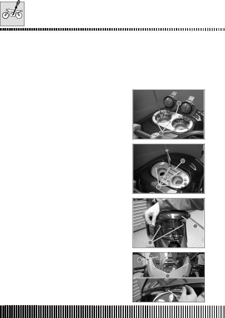
MAINTENANCE
MAINTENANCE AND TUNING
This section describes the servicing procedures for each part of periodical maintenance.
FUEL TANK REMOVAL
To complete this operation it is necessary to previously remove the seat.
•Remove the complete fuel tap assembly by unscrewing the three screws 1 indicated in the figure.
•Extract the flange 2 of the petrol covers.
•Remove the six screws 3 using an 8mm spanner.
•Extract the plate 4 paying attention to the two washers underneath.
• Remove the tank cover 5 by unscrewing the two screws 6.
•Remove the windshield 7 by unscrewing the three screws 8 shown in the figure.
2
1
4
3
5
6
7
8
8
B.4
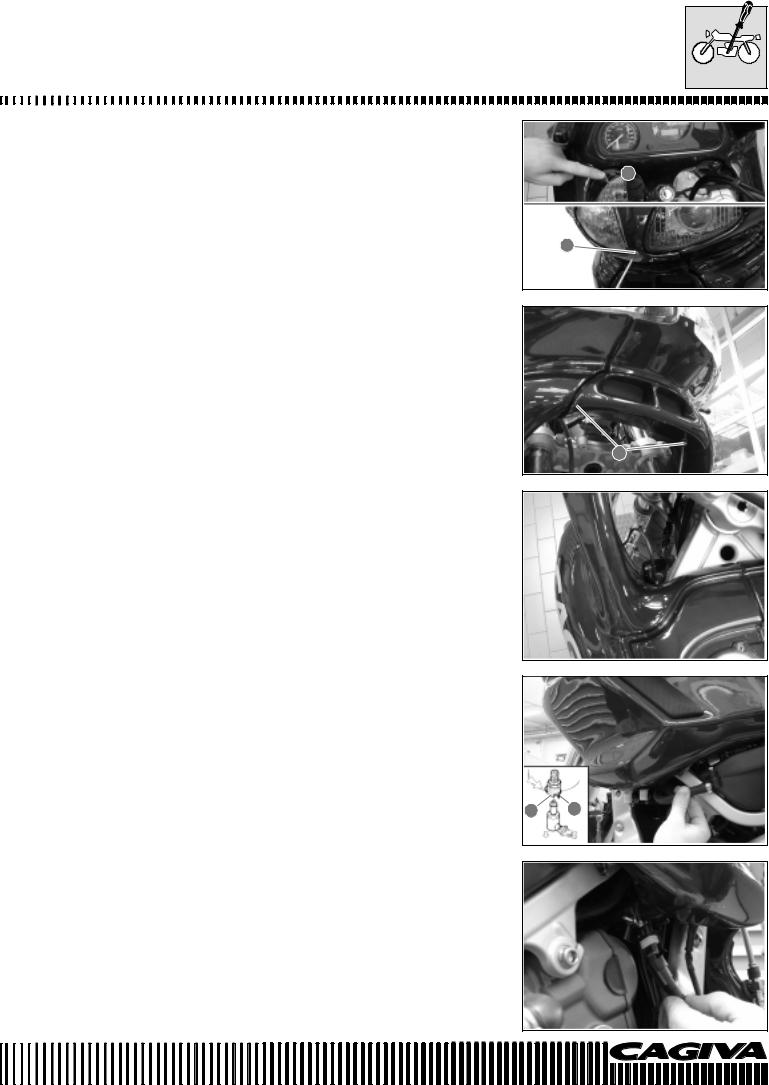
MAINTENANCE
•Remove the fairing by unscrewing the five screws 1. There is one front screw and four screws highlighted in the figure.
1 
1
•Remove the front protection by unscrewing the two lower screws 2, as shown in the figure.
2
•Disconnect the indicator connectors. One is indicated in the figure and the other is on the opposite side of the machine.
•Disconnect the fuel tubes from the left fuel tank. The fuel tubes are attached to the fuel tank by rapid attachments and their removal automatically blocks the exit of fuel. It is necessary to push the lever 3 and slide out the elbow union 4 to disassemble it. Before effecting reassembly, check that the small pin 4 is completely extended. If it is not in position, push on the lever 3 to bring it into position.
3 4
•Disconnect the reserve fuel sensor connector attached to the right fuel tank.
B.5
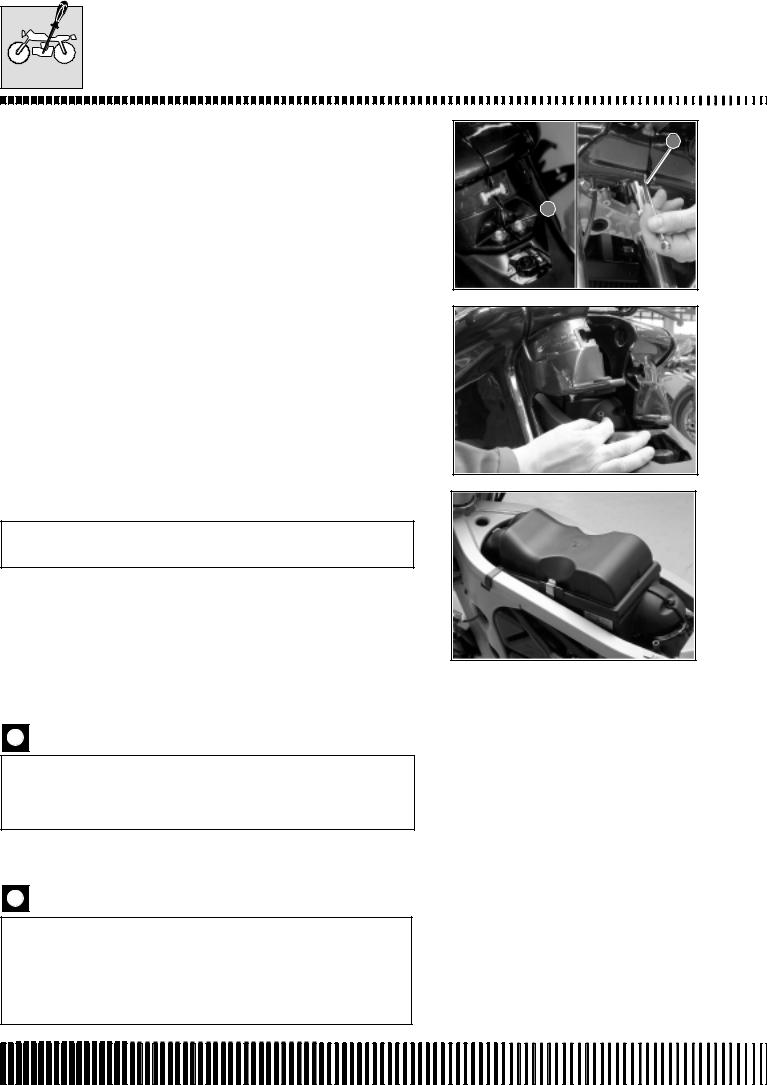
MAINTENANCE
• Slacken and remove the two tank union clamps 1. One is situated |
|
at the front of the vehicle and the other at the back of the tank. |
1 |
 1
1
•Finally, remove the two fixing screws 2. Disconnect the overflow tube from the left fuel tank.
AIR FILTER
Check every 6000 km (or 6 months)
Substitute every 12000 km (or 12 months).
•It is necessary to remove the fuel tanks before removing the air filter.
•Carefully eliminate dust and dirt from the filter element by using compressed air.
The compressed air must be blown from the exterior of the filter element. If compressed air is used internally, the dust and dirt will be pushed into the pores of the filter thereby reducing the flow of air to the same element.
•To assemble a clean or new filter element, carry out the operation of disassembly in the reverse order.
Should the motorcycle be used frequently on dusty roads, the filter element must be cleaned more frequently. The use of the engine without a filter or with a broken filter element will certainly shorten the life of the engine. Check that the air filter is always in good condition. The long life of the engine depends a lot on this component!
B.6
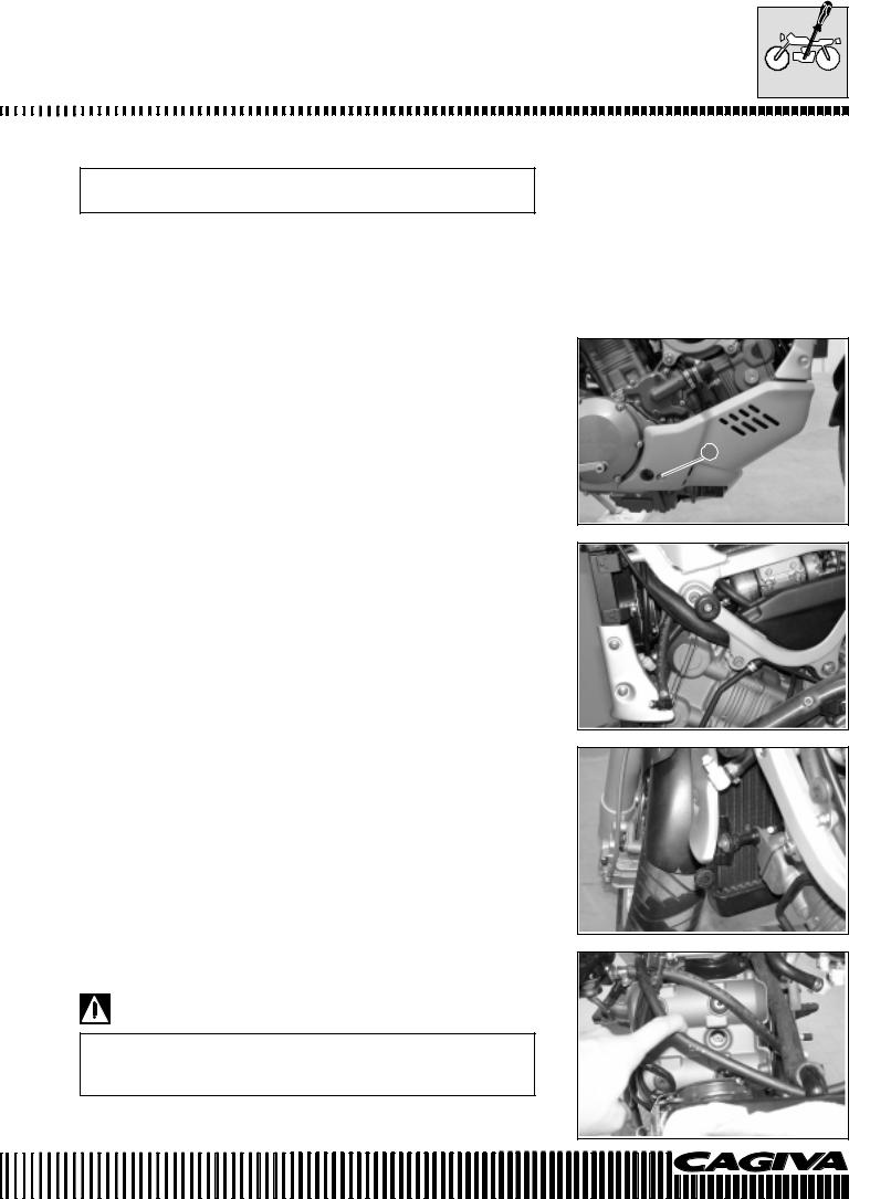
MAINTENANCE
SPARK PLUGS
Check every 6000 km (or 6 months)
Substitute every 12000 km (or 12 months)
After the first 1000 km it is necessary to remove the spark plugs, clean them and check the distance between the electrodes (0.6÷0.7 mm).
REMOVAL OF SPARK PLUG N° 1 (FRONT)
•Remove the sump guard by unscrewing the two screws 1. One screw is indicated in the figure whilst the other screw is on the other side.
•Disconnect the fuel tubes.
•Remove the left side protection of the radiator.
•Remove the lower radiator fixing and its spacer. Unhook the radiator from its mountings.
•Push the radiator down so that there is access to the forward spark plug.
•Remove the spark plug insulated cap.
•Unscrew the spark plug as shown in the figure.
During this operation, pay attention to the front mudguard. Place a piece of cloth between the radiator and the mudguard as shown in the figure.
1
B.7
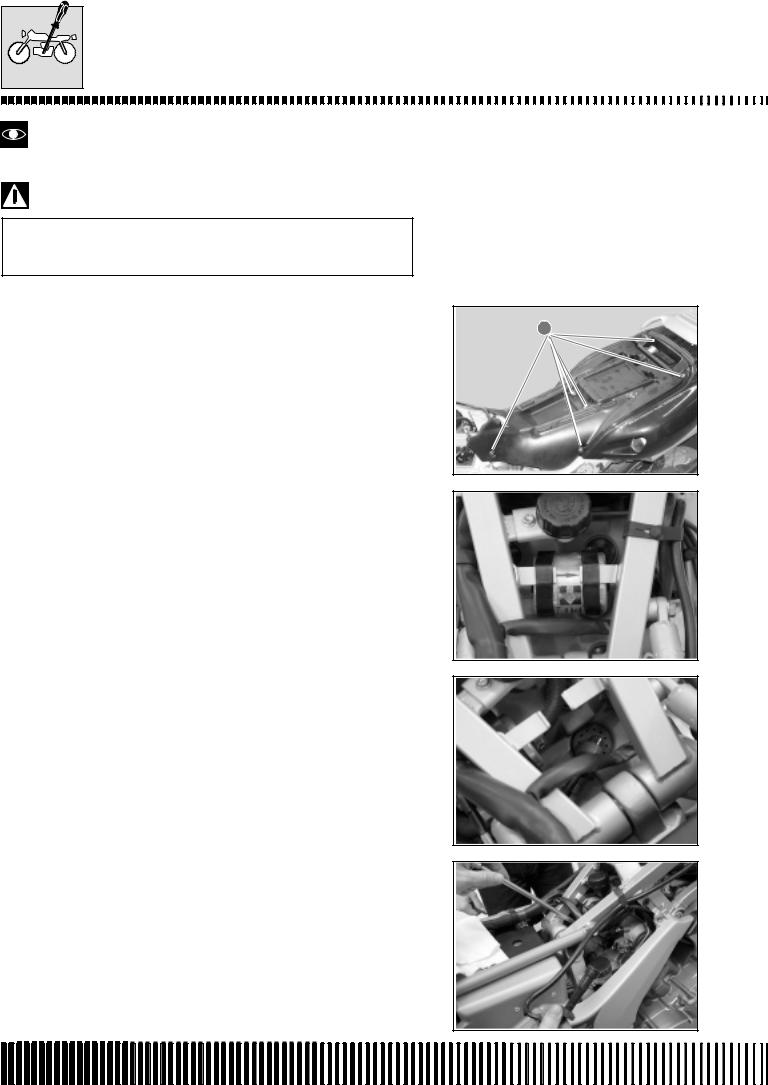
MAINTENANCE
Be careful to not damage the finning of the radiator.
The radiator and engine can provocate serious burns when they are hot. Wait until the radiator and the engine are cool enough to be touched before carrying out this operation.
REMOVAL OF SPARK PLUG N° 2 (REAR)
•Remove the seat.
•Remove the seat compartment by unscrewing the eight screws 1. Six of theses screws are shown in the figure.
•Unhook the rubber mountings of the fuel filter.
•Remove the spark plug insulated cap.
•Remove the spark plug.
1 |
B.8
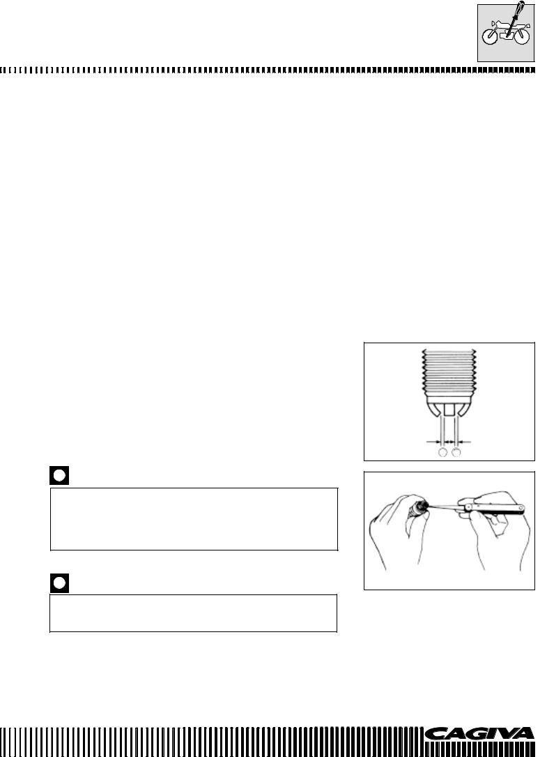
MAINTENANCE
HEAT GRADE CODE
• Check the heat grade code of the spark plug.
|
|
NGK |
CR8EK |
|
|
DENSO |
U24ETR |
|
|
|
|
|
|
|
|
The type “R” spark plug has a resistor on the central electrode to avoid radio disturbance.
CARBON DEPOSITS
•Check the spark plugs for carbon deposits. If there are deposits, use the appropriate machine or a pointed tool to eliminate them. Take care in using the pointed tool.
THE GAP BETWEEN THE SPARK PLUG ELECTRODES
• Measure the gap between the spark plug electrodes using feeler blades. Adjust the gap if it is not correct, using the following information:
Specific tool:
Standard
Normal gap between the electrodes of the spark plug A: 0,6÷0,7 mm
THE CONDITION OF THE ELECTRODES
•Controllare se gli elettrodi sono usurati o bruciati. Se essi fossero estremamente usurati o bruciati,sostituire la candela.
Sostituire la candela anche in caso di rottura dell’isolante o danneggiamento della filettatura.
When a spark plug substitution is made, check the pitch size and the length of the thread. If the threading is too short, carbon residues will be deposited on the threading of the cylinder head thereby possibly causing damage to the engine.
REPLACING THE SPARK PLUG AND INSULATED CAP
Carefully screw the spark plug into place by hand before tightening with a plug spanner. This is to avoid damage to the aluminium threading.
•Manually screw in the spark plugs into the cylinder heads and tighten them to the specific torque.
Torque pressure
Spark plug: 11 N·m (1,1 kg-m)
A A
B.9
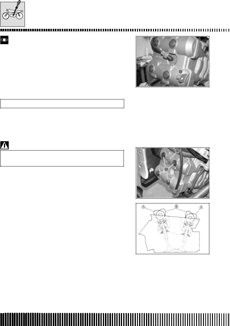
MAINTENANCE
When the front and rear spark plug insulated caps are pushed on, turn the triangular signs on the insulated caps A towards the exhaust side of the cylinders.
VALVE TAPPET CLEARANCE ADJUSTMENT
Check every 24000 km (or every two years)
A
• Remove the seat.
FRONT CYLINDER
•Remove the spark plug as described in page B-7.
•Remove the front cylinder head valve cover 1 by unscrewing the four screws 2 shown in the figure.
1
When removing the valve cover, be careful that the locating pins or the gasket do not fall to the ground or inside the cover opening.
2
The valve tappet clearances vary between the inlet and the exhaust valves.
The valve tappet clearance adjustment must be checked and adjusted:
1)During periodical maintenance.
2)When tappet maintenance is carried out.
3)When the camshafts are removed for maintenance.
Valve tappet clearances (cold): |
|
|||
Inlet |
: 0.10 - 0.20 mm |
|
||
Exhaust |
: 0.20 - 0.30 mm |
IN. |
||
|
|
|
||
|
|
|
||
* Valve tappet clearances must be checked when the piston is in |
EX. |
|||
the top dead centre (T.D.C.) position of the compression cycle. |
||||
|
||||
*The inlet and exhaust cams of the front cylinder in position A indicate that the front piston is in the top dead centre (T.D.C.) position of the compression cycle.
*The inlet and exhaust cams of the rear cylinder in position B indicate that the rear piston is in the top dead centre (T.D.C.) position of the compression cycle.
*Specified valve tappet clearances are with a COLD engine.
*Use a 17 mm spanner to turn the camshaft when checking the valve tappet clearances. The camshaft must be turned in the direction of normal engine operation. Both spark plugs must be removed.
B.10
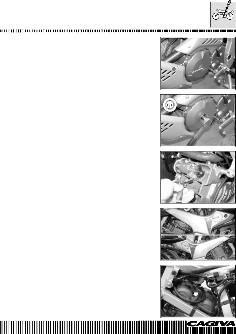
MAINTENANCE
•Remove the plug of the generator cover 1 and the timing cover inspection plug 2.
2
1
•Turn the engine camshaft to bring the piston of the N° 1 cylinder (front) to the top dead centre (T.D.C.) position of the compression cycle. Align the “F/T” line on the generator rotor with the timing inspection hole line and bring the camshafts to the indicated position in page B- 10.)
•To check the valve tappet clearances of the N° 1 cylinder (front), insert a feeler gauge between the valve stem and the cam. If the clearance is not correct, adjust it within the specified range.
REAR CYLINDER
•Remove the seat, the seat compartment and the spark plug as described in page B-8.
•Remove the left and right hand side panels by unscrewing the two screws.
•Disconnect the oil vapour tube from the left hand side of the machine.
B.11

MAINTENANCE
•Unhook the rear brake fluid chamber by unscrewing the screw shown in the figure.
•Disconnect the electrical connector of the camshaft position sensor.
•Remove the sensor by unscrewing the two relative screws.
•Disassemble the fuel filter from its supports and disconnect it from the fuel tubes, taking care to not spill any fuel.
Place a cloth underneath the fuel filter.
• Disassemble the expansion tank cover assembly.
•Remove the rear cylinder head valve cover by unscrewing the four relative screws shown in the figure.
•Rotate the crankshaft 270° (3/4 of a turn) to bring the piston of N° 2 cylinder (rear) to T.D.C. of the compression cycle. Align the “R/ T” line on the rotor of the generator with the counter-line of the timing synchronisation inspection hole and bring the camshafts in the position indicated at page B-7.
B.12
MAINTENANCE
•Check the valve tappet clearance of the N° 2 cylinder (rear) using the same procedure used for the N° 1 cylinder (front) and adjust as necessary.
VALVE TAPPET CLEARANCE ADJUSTMENT
The valve tappet clearance adjustment is regulated by the substitution of the valve stem pad with another that is thicker or thinner.
•After having removed the cylinder head valve covers, remove the intake and exhaust camshafts as described in chapter D.
•Remove the cup and pad with the fingers or a magnet.
•Check the number on the pad. This number indicates the thickness of the pad as illustrated.
•Choose a substitute pad that allows a valve tappet clearance within the prescribed range. There are 25 sizes of pad available that vary in thickness from 2.30 mm to 3.50 mm in increments of 0.05 mm. Insert the chosen pad into the valve stem end with the numbers towards the cam.
Check the thickness of the pad with a micrometer to ascertain that it is the correct size.
See the selection table of the thickness of the pads for details. (Pages B-10 and B-11).
*Do not forget to apply some engine oil to the surfaces of the pad.
*During the positioning of the pad, check that the surface with the numbers points towards the tappets.
Reassemble the camshafts in the correct way. (See page D-102)
•After having reassembled the pads and the camshafts, rotate the engine so that the valve mechanism becomes completely depressed. This causes the expulsion of any oil entrapped in the seat between the pad and the cam that could probably cause incorrect clearances. Check again the clearance to verify that it is within the prescribed limits.
•Reassemble the following parts after having completed the valve tappet clearance check.
|
|
|
|
|
|
|
|
|
|
|
|
|
|
|
|
|
|
|
|
|
|
|
|
|
|
|
|
|
|
|
|
|
|
|
|
|
|
|
|
|
|
|
|
|
|
|
|
|
|
Page |
|
|
|
|
|
|
|
|
|
|
|
|
|
|
|
|
|
|
|
|
|
|
|
|
|
|
|
|
|
|
|
|
|
|
|
|
|
|
|
|
|
|
|
||||||||||||||||||||||||||||||||||||
* Cylinder head valve covers .................................................. |
|
|
|
|
|
|
|
|
|
|
|
|
|
|
|
|
D-78 |
|
|
|
|
|
|
|
|
|
|
|
|
|
|
|
|
|
|
|
|
|
|
|
|
|
|
|
|
|
|
|
|
|
|
|
|
|
|
|
|
|
|
|
|||||||||||||||||||||||||||||||||||||||||||||||||||||||||||||||||||||
* Spark plugs and insulated caps ................................... |
|
|
|
|
|
|
|
|
|
|
|
|
B-5 e B-6 |
|
|
|
|
|
|
|
|
|
|
|
|
|
|
|
|
|
|
|
|
|
|
|
|
|
|
|
|
|
|
|
|
|
|
|
|
|
|
|
|
|
|
|
|||||||||||||||||||||||||||||||||||||||||||||||||||||||||||||||||||||||||
* Timing synchronisation inspection cover .............................. |
|
|
|
|
|
|
|
|
|
|
|
|
|
|
|
|
D-79 |
|
|
|
|
|
|
|
|
|
|
|
|
|
|
|
|
|
|
|
|
|
|
|
|
|
|
|
|
|
|
|
|
|
|
|
|
|
|
|
|
|
|
|
|||||||||||||||||||||||||||||||||||||||||||||||||||||||||||||||||||||
* Generator cover screw ......................................................... |
|
|
|
|
|
|
|
|
|
|
|
|
|
|
|
|
D-79 |
|
|
|
|
|
|
|
|
|
|
|
|
|
|
|
|
|
|
|
|
|
|
|
|
|
|
|
|
|
|
|
|
|
|
|
|
|
|
|
|
|
|
|
|||||||||||||||||||||||||||||||||||||||||||||||||||||||||||||||||||||
|
|
|
|
|
|
|
|
|
|
|
|
|
|
|
|
|
|
|
|
|
|
|
|
|
|
|
|
|
|
|
|
|
|
|
|
|
|
|
|
|
|
|
|
|
|
|
|
|
|
|
|
|
|
|
|
|
|
|
|
|
|
|
|
|
|
|
|
|
|
|
|
|
|
|
|
|
|
|
|
|
|
|
|
|
|
|
|
|
|
|
|
|
|
|
|
|
|
|
|
|
|
|
|
|
|
|
|
|
|
|
|
|
|
|
|
|
|
|
|
|
|
|
|
|
|
|
|
|
|
|
|
|
|
|
|
|
|
|
|
|
|
|
|
|
|
|
|
|
|
|
|
|
|
|
|
|
|
|
|
|
|
|
|
|
|
|
|
|
|
|
|
|
|
|
|
|
|
|
|
|
|
|
|
|
|
|
|
|
|
|
|
|
|
|
|
|
|
|
|
|
|
|
|
|
|
|
|
|
|
|
|
|
|
|
|
|
|
|
|
|
|
|
|
|
|
|
|
|
|
|
|
|
|
|
|
|
|
|
|
|
|
|
|
|
|
|
|
|
|
|
|
|
|
|
|
|
|
|
|
|
|
|
|
|
|
|
|
|
|
|
|
|
|
|
|
|
|
|
|
|
|
|
|
|
|
|
|
|
|
|
|
|
|
|
|
|
|
|
|
|
|
|
|
|
|
|
|
|
|
|
|
|
|
|
|
|
|
|
|
|
|
|
|
|
|
|
|
|
|
|
|
|
|
|
|
|
|
|
|
|
|
|
|
|
|
|
|
|
|
|
|
|
|
|
|
|
|
|
|
|
|
|
|
|
|
|
|
|
|
|
|
|
|
|
|
|
|
|
|
|
|
|
|
|
|
|
|
|
|
B.13
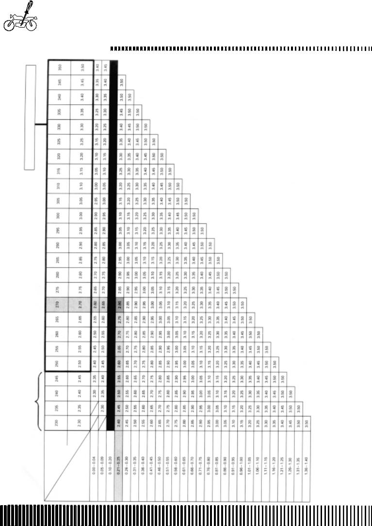
|
|
|
|
|
|
|
|
|
|
|
|
|
|
|
|
|
|
|
|
|
|
|
|
|
|
|
|
|
|
|
|
|
|
|
|
|
|
|
|
|
|
|
|
|
|
|
|
|
|
|
|
|
|
|
|
|
|
|
|
|
|
|
|
|
|
|
|
|
|
|
|
|
|
|
|
|
|
|
|
|
|
|
|
|
|
|
|
|
|
|
|
|
|
|
|
|
|
|
|
|
|
|
|
|
|
|
|
|
|
|
|
|
|
|
|
|
|
|
|
|
|
|
|
|
|
|
|
|
|
|
|
|
|
|
|
|
|
|
|
|
|
|
|
|
|
|
|
|
|
|
|
|
|
|
|
|
|
|
|
|
|
|
|
|
|
|
|
|
|
|
|
|
|
|
|
|
|
|
|
|
|
|
|
|
|
|
|
|
|
PADSET |
-41810) |
|
|
|
|
|
|
|
|
|
|
|
|
|
|
|
|
|
|
|
|
|
|
|
|
|
|
|
|
|
|
|
|
|
|
|
|
|
|
|
|
|
|||
|
|
|
|
|
|
|
|
|
|
|
|
|
VALVE |
(12800 |
|
|
|
|
|
|
|
|
|
|
|
|
|
|
|
|
|
|
|
|
|
|
|
|
|
|
|
|
|
|
|
|
|
|
|
|
|
|
|
|
|
|||
NO. (12892.41C00.XXX)
INTAKE VALVE PADS SELECTION TABLE
OPTIONAL
SUFFIXNO. |
ACTUAL PAD THICKNESS (mm) |
MEASURED CLEARANCE (mm)
B.14
MAINTENANCE
(INTAKE SIDE)
SPECIFIED CLEARANCE/NO ADJUSTMENT NECESSARY
HOW TO USE THIS TABLE: 1. Measure the clearance of the valve (cold engine). 2. Measure the thickness of the actual pad. 3. Make the vertical column (valve tappet clearance) and horizontal column (thickness) match. FOR EXAMPLE The valve tappet clearance is 0.23 mm The thickness of the actual pad is 0.70 mm The pad to use is 2.80 mm

|
|
|
|
|
|
|
|
|
|
|
|
|
|
|
|
|
|
|
|
|
|
|
|
|
|
|
|
|
|
|
|
|
|
|
|
|
PADSET |
-41810) |
|
|
|
|
|
|
|
|
|
|
|
|
|
|
|
|
|
|
|
|
|
|
|
|
|
|
|
|
|
|
VALVE |
(12800 |
|
|
|
|
|
|
|
|
|
|
|
|
|
|
|
|
|
|
|
|
|
|
|
|
|
NO. (12892.41C00.XXX)
EXHAUST VALVE PADS SELECTION TABLE
OPTIONAL
SUFFIXNO. |
ACTUAL PAD THICKNESS (mm) |
MEASURED CLEARANCE (mm)
MAINTENANCE
(EXHAUST SIDE)
SPECIFIED CLEARANCE/NO ADJUSTMENT NECESSARY
HOW TO USE THIS TABLE: 1. Measure the clearance of the valve (cold engine). 2. Measure the thickness of the actual pad. 3. Make the vertical column (valve tappet clearance) and horizontal column (thickness) match. FOR EXAMPLE The valve tappet clearance is 0.23 mm The thickness of the actual pad is 0.70 mm The pad to use is 2.80 mm
B.15
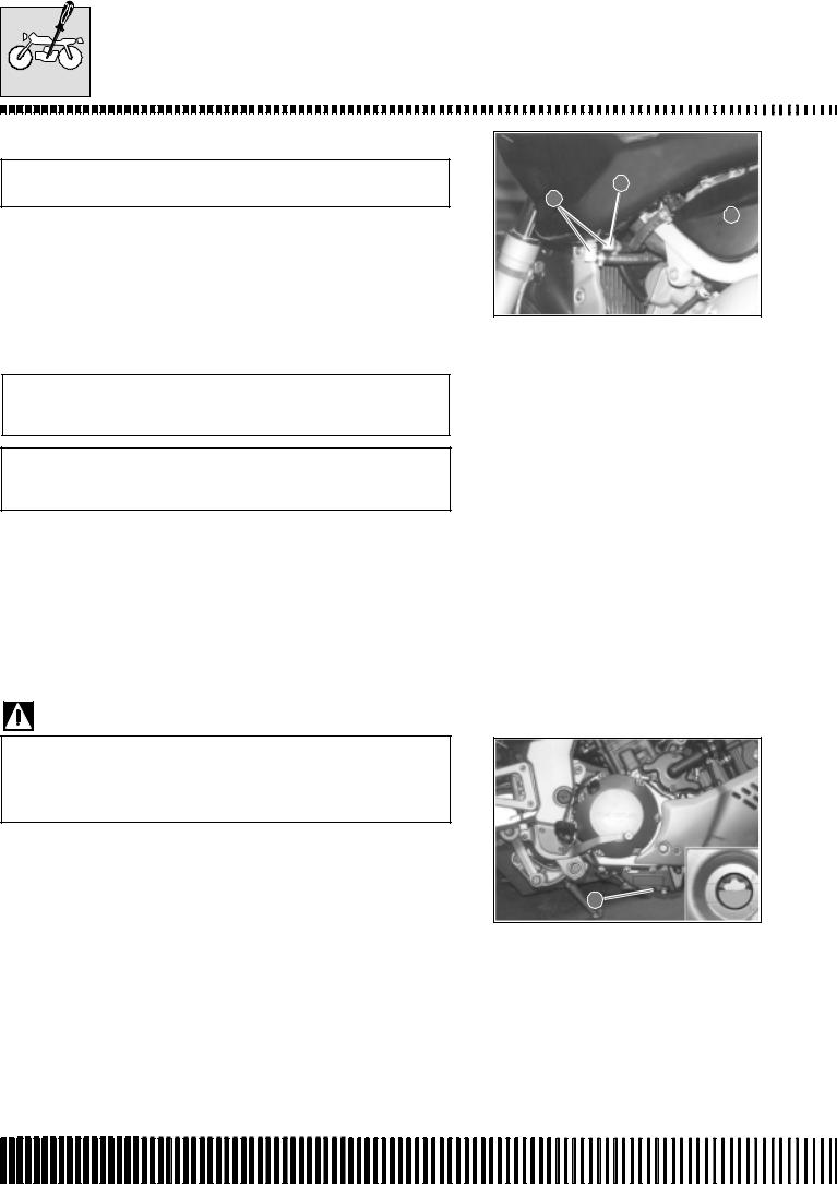
MAINTENANCE
FUEL TUBING
Check every 6000 km (or 6 months).
Substitute every 4 years.
2
3
 1
1
After removing the fuel tank, check to see if the feed tube 1 and return tubes 2 and 3 are damaged or show signs of leaking. Substitute the tubes if any defects are found.
ENGINE OIL AND OIL FILTER
(ENGINE OIL)
Change at 1000 km (or 1 month). Change every 6000 km (or 6 months).
(OIL FILTER)
Substitute at 1000 km (or 1 month). Substitute every 18000 km (18 months).
The oil must be changed whilst the engine is hot. The oil filter must be substituted at the above-mentioned intervals at the same time as an oil change.
ENGINE OIL CHANGE
•Place the machine in a vertical position.
•Place a container underneath the engine and drain the used oil into the container by unscrewing the sump plug 1 and the filling plug 2.
Used oil contains dangerous substances that can damage the environment. To change the oil it is recommended to use our service network that can dispose of the oil respecting the environment and the norms in force.
•Tighten the sump plug 1 to the specified torque and pour new oil into the filling hole 2. The engine holds 3.1 litres of oil. Use only oil
with an API SF or SG classification and a viscosity of SAE 10W/ |
1 |
40. |
|
Torque pressure
Sump plug: 23 N.m (2.3 kg-m)
•Switch on the engine and leave it to heat up for several minutes.
•Switch off the engine and wait approximately one minute. Check the oil level in the inspection window 3. If the level is below the countersign “L”, add oil until it reaches the countersign “F”. If the level exceeds the countersign “F” then discharge enough oil to arrive at the countersign “F”.
B.16
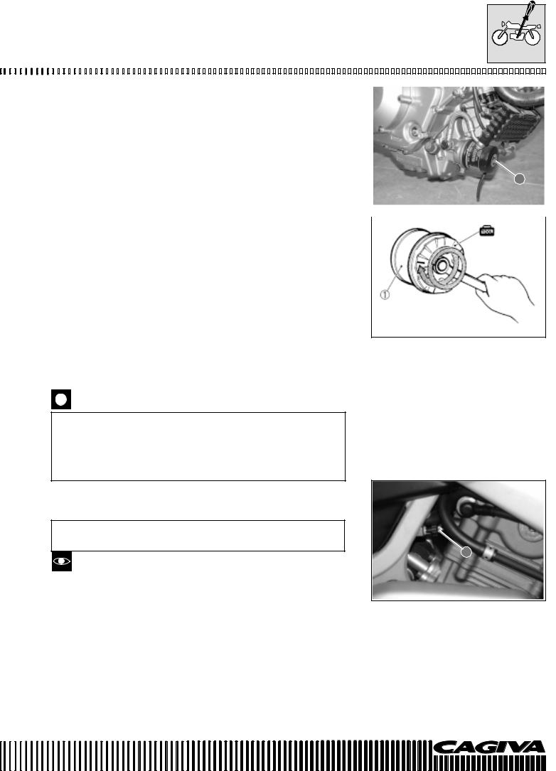
MAINTENANCE
|
|
|
|
|
|
|
|
|
|
|
|
|
|
|
|
|
|
|
|
|
|
|
|
|
|
|
|
|
|
|
|
|
|
|
|
|
|
|
|
|
|
|
|
|
|
|
|
|
|
|
|
|
|
|
|
|
|
|
|
|
|
|
|
|
|
|
|
|
|
|
|
|
|
|
|
|
|
|
|
|
|
|
|
|
|
|
|
|
|
|
|
|
|
|
|
|
|
|
|
|
|
|
|
|
|
|
|
|
|
|
|
|
|
|
|
|
|
|
OIL FILTER SUBSTITUTION |
|
|
|
|
|
|
|
|
|
|
|
|
|
|
|
|
|
|
|
|
|
|
|
|
|
|
|
|
|
|
|
|
|
|
|
|
|
|
|
|
|
|
|
|
|
|
|
|
|
|
|
|
|
|
|
|
|
|
|
|
|
|
|
|
||||||||||||||||||||||||||||||||||||||||||||||||||||||
|
|
|
|
|
|
|
|
|
|
|
|
|
|
|
|
|
|
|
|
|
|
|
|
|
|
|
|
|
|
|
|
|
|
|
|
|
|
|
|
|
|
|
|
|
|
|
|
|
|
|
|
|
|
|
|
|
|
|
|
|
|
|
|
|||||||||||||||||||||||||||||||||||||||||||||||||||||||
• Drain the engine oil following the same procedure described for |
|
|
|
|
|
|
|
|
|
|
|
|
|
|
|
|
|
|
|
|
|
|
|
|
|
|
|
|
|
|
|
|
|
|
|
|
|
|
|
|
|
|
|
|
|
|
|
|
|
|
|
|
|
|
|
|
|
|
|
|
|
|
|
|
||||||||||||||||||||||||||||||||||||||||||||||||||||||
|
|
the oil change. |
|
|
|
|
|
|
|
|
|
|
|
|
|
|
|
|
|
|
|
|
|
|
|
|
|
|
|
|
|
|
|
|
|
|
|
|
|
|
|
|
|
|
|
|
|
|
|
|
|
|
|
|
|
|
|
|
|
|
|
|
|
|
|
|
||||||||||||||||||||||||||||||||||||||||||||||||||||
• Remove the oil filter 1 utilising the appropriate wrench (special |
|
|
|
|
|
|
|
|
|
|
|
|
|
|
|
|
|
|
|
|
|
|
|
|
|
|
|
|
|
|
|
|
|
|
|
|
|
|
|
|
|
|
|
|
|
|
|
|
|
|
|
|
|
|
|
|
|
|
|
|
|
|
|
|
||||||||||||||||||||||||||||||||||||||||||||||||||||||
|
|
tool). |
|
|
|
|
|
|
|
|
|
|
|
|
|
|
|
|
|
|
|
|
|
|
|
|
|
|
|
|
|
|
|
|
|
|
|
|
|
|
|
|
|
|
|
|
|
|
|
|
|
|
|
|
|
|
|
|
|
|
|
|
|
|
|
|
||||||||||||||||||||||||||||||||||||||||||||||||||||
• Apply a light layer of engine oil to the gasket of the new filter be- |
|
|
|
|
|
|
|
|
|
|
|
|
|
|
|
|
|
|
|
|
|
|
|
|
|
|
|
|
|
|
|
|
|
|
|
|
|
|
|
|
|
|
|
|
|
|
|
|
|
|
|
|
|
|
|
|
|
|
|
|
|
|
|
|
||||||||||||||||||||||||||||||||||||||||||||||||||||||
|
|
fore assembly. |
|
|
|
|
|
|
|
|
|
|
|
|
|
|
|
|
|
|
|
|
|
|
|
|
|
|
|
|
|
|
|
|
|
|
|
|
|
|
|
|
|
|
|
|
|
|
|
|
|
|
|
|
|
|
|
|
|
|
|
|
|
|
|
|
||||||||||||||||||||||||||||||||||||||||||||||||||||
• Assemble the new filter by screwing it in by hand until the gasket |
|
|
|
|
|
1 |
|
|
|
|
|
|
|
|
||||||||||||||||||||||||||||||||||||||||||||||||||||||||||||||||||||||||||||||||||||||||||||||||||||||||
|
|
comes into contact with the oil filter container. Tighten by two turns |
|
|
|
|
|
|
|
|
|
|||||||||||||||||||||||||||||||||||||||||||||||||||||||||||||||||||||||||||||||||||||||||||||||||||||||||||
|
|
|
|
|
|
|
|
|
|
|
|
|
|
|
|
|
|
|
|
|
|
|
|
|
|
|
|
|
|
|
|
|
|
|
|
|
|
|
|
|
|
|
|
|
|
|
|
|
|
|
|
|
|
|
|
|
|
|
|
|
|
|
|
|
|
|||||||||||||||||||||||||||||||||||||||||||||||||||||
|
|
utilising the oil filter wrench (special tool). |
|
|
|
|
|
|
|
|
|
|
|
|
|
|
|
|
|
|
|
|
|
|
|
|
|
|
|
|
|
|
|
|
|
|
|
|
|
|
|
|
|
|
|
|
|
|
|
|
|
|
|
|
|
|
|
|
|
|
|
|
|
|
|
|
||||||||||||||||||||||||||||||||||||||||||||||||||||
Special tool: 800096659: Oil filter wrench |
|
|
|
|
|
|
|
|
|
|
|
|
|
|
|
|
|
|
|
|
|
|
|
|
|
|
|
|
|
|
|
|
|
|
|
|
|
|
|
|
|
|
|
|
|
|
|
|
|
|
|
|
|
|
|
|
|
|
|
|
|
|
|
|
||||||||||||||||||||||||||||||||||||||||||||||||||||||
|
|
|
|
|
|
|
|
|
|
|
|
|
|
|
|
|
|
|
|
|
|
|
|
|
|
|
|
|
|
|
|
|
|
|
|
|
|
|
|
|
|
|
|
|
|
|
|
|
|
|
|
|
|
|
|
|
|
|
|
|
|
|
|
|||||||||||||||||||||||||||||||||||||||||||||||||||||||
|
|
|
|
|
|
|
|
|
|
|
|
|
|
|
|
|
|
|
|
|
|
|
|
|
|
|
|
|
|
|
|
|
|
|
|
|
|
|
|
|
|
|
|
|
|
|
|
|
|
|
|
|
|
|
|
|
|
|
|
|
|
|
|
|||||||||||||||||||||||||||||||||||||||||||||||||||||||
|
|
|
|
|
|
|
|
|
|
|
|
|
|
|
|
|
|
|
|
|
|
|
|
|
|
|
|
|
|
|
|
|
|
|
|
|
|
|
|
|
|
|
|
|
|
|
|
|
|
|
|
|
|
|
|
|
|
|
|
|
|
|
|
|
|
|
|
|
|
|
|
|
|
|
|
|
|
|
|
|
|
|
|
|
|
|
|
|
|
|
|
|
|
|
|
|
|
|
|
|
|
|
|
|
|
|
|
|
|
|
|
|
|
|
|
|
|
|
|
|
|
|
|
|
|
|
|
|
|
|
|
|
|
|
|
|
|
|
|
|
|
|
|
|
|
|
|
|
|
|
|
|
|
|
|
|
|
|
|
|
|
|
|
|
|
|
|
|
|
|
|
|
|
|
|
|
|
|
|
|
|
|
|
|
|
|
|
|
|
|
|
|
|
|
|
|
|
|
|
|
|
|
|
|
|
|
|
|
|
|
|
|
|
|
|
|
|
|
|
|
|
|
|
|
|
|
|
|
|
|
|
|
|
|
|
|
|
Tighten the filter correctly by utilising the special wrench.
Never tighten the oil filter by hand.
•Refill with new engine oil and check the level by following the same procedure used for the oil change.
OIL CAPACITY
Oil change: 3.1 litres
Oil filter change: 3.3 litres
Engine overhaul: 3.6 litres
Utilise only ORIGINAL CAGIVA OIL FILTERS. Filters and spare parts of other makes could differ with regards to the threading (diameter and pitch), filter performance and duration. Possible damage may occur to the engine with consequent loss of oil.
MINIMUM TICKOVER
Check at 1000 km (or 1 month). Every 6000 km (or 6 months).
1
Carry out this adjustment when the engine is hot.
•Switch on the engine and adjust the tickover as specified by rotating the accelerator stop screw 1.
Minimum tickover: 1300±1350 rpm
B.17
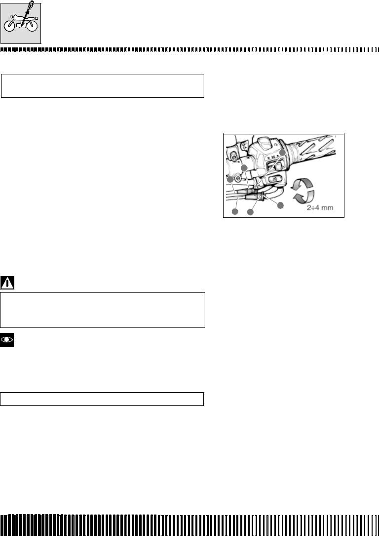
MAINTENANCE
ACCELERATOR CABLE PLAY
Check at 1000 km (or 1 month)
Every 6000 km (or 6 months).
Adjust the accelerator cable play following these three phases.
First phase:
•Slacken the locknut 1 of the accelerator return cable B and completely screw in the screw adjuster 2.
Second phase:
•Slacken the locknut 3 of the accelerator opening cable A.
•Screw or unscrew the screw adjuster 4 until the accelerator cable play is 2.0 – 4.0 mm at the accelerator handgrip.
•Tighten the locknut 3 whilst keeping the screw adjuster 4 locked in position.
Third phase:
•Keeping the accelerator handgrip in the closed position, slowly unscrew the screw adjuster 2 of the accelerator return cable B until a resistance is felt.
•Tighten the locknut 1 whilst keeping the screw adjuster 2 locked in position.
Accelerator cable play: 2.0-4.0 mm
3
4
A
B |
1 |
2 |
After making the adjustments, check that the handlebar movement does not cause an increase in the tickover. The accelerator handgrip should return smoothly and automatically into position without any stiffness.
Greater adjustments can be carried out using the lateral adjuster on the butterfly valve body of the carburettor.
SYNCHRONISATION OF THE CARBURETTORS
Check every 12000 km (or 12 months)
(See page C-73)
B.18
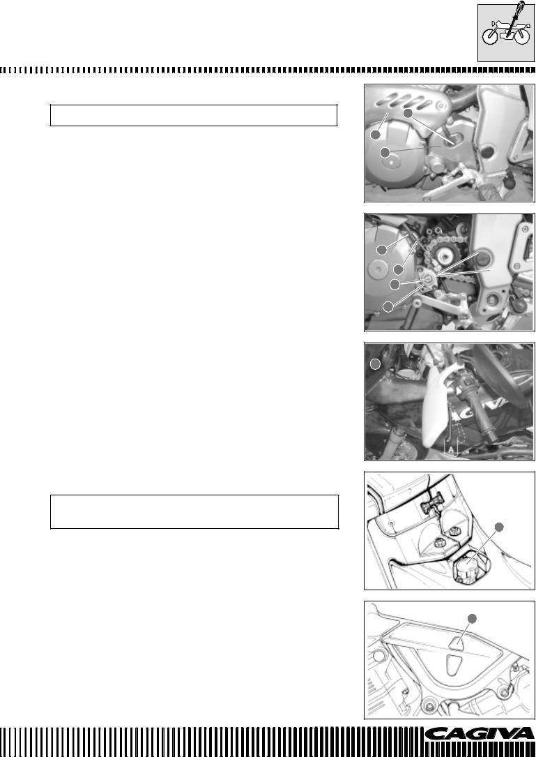
MAINTENANCE
CLUTCH
Check every 6000 km (or 6 months).
•Remove the speed sensor 1.
•Remove the left hand footrest from the frame by unscrewing the two relative screws.
•Remove the engine pinion cover 2 by unscrewing the three relative screws.
•Remove the exhaust protection 3.
•Screw in the clutch lever assembly adjuster screw 8.
•Slacken the locknut 4 and completely unscrew the screw adjuster
5.
•Slacken the locknut 6 and rotate the screw adjuster 7 to obtain 5 - 10 degrees of play at the end of the clutch lever.
•Tighten the locknut 6.
•Slowly screw in the adjuster screw 5 until resistance is felt.
•Unscrew the screw adjuster 5 a 1/4 of a turn and then tighten the locknut 4.
•Screw or unscrew the screw adjuster 8 to obtain 10-15 mm of play A at the end of the clutch lever.
Clutch lever play A: 10-15 mm
1
3
2 
7
6 |
→ |
5°-10° |
|
|
|
5 |
|
|
4
8 
COOLING SYSTEM
Check every 1000 km (or 1 month)
Substitute the engine coolant every two years
ENGINE COOLANT LEVEL CHECK
The cooling of the engine is by forced circulation with a centrifugal pump (situated on the left side of the engine), a by-pass valve thermostat and a radiator. The opening of the thermostat and the consequent flow of liquid in the radiator are activated when the temperature reaches ª 82°C. (maximum opening 95°C.). The system contains ª 2.3 litres of AGIP COOL engine coolant.
Make sure that the machine is on level ground and that it is in a vertical position with both wheels placed on the ground.
Check that the level inside the expansion tank is between the MIN and MAX levels shown on the left hand side of the machine 2.
If necessary, top up the engine coolant via the cap 1 positioned underneath the seat.
1
2
B.19
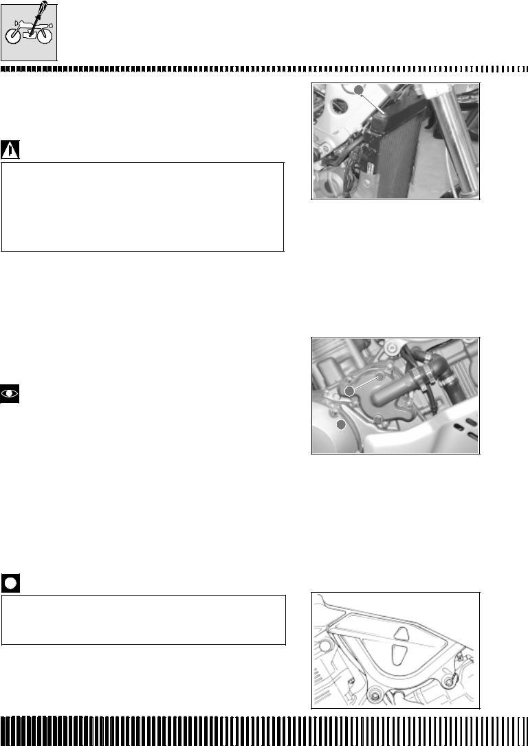
MAINTENANCE
ENGINE COOLANT CHANGE
•After having removed the tank, remove the radiator cap 1, the expansion tank cap and the drain plugs 2 end 3. Drain the engine coolant.
*Do not remove the radiator cap when the engine is hot. Boiling liquid or steam can cause serious burns.
*The engine coolant is harmful if swallowed or if it comes into contact with the skin or the eyes. If the coolant comes into contact with the skin or eyes, rinse abundantly with water. If it is swallowed, provocate vomiting and immediately call a doctor.
•Wash the radiator with water if necessary.
•Tighten the coolant drain plugs 2 and 3 to the specified torque.
Torque pressure
Coolant drain plugs 2 and 3: 13 N.m (1.3 kg-m)
•Via the refill hole 5, fill the radiator with the specified engine coolant until it reaches the neck of the radiator.
•Bleed air out of the system via the bleed nut 2.
See chapter H for information regarding the engine coolant.
•Tighten the air bleed nut to the specified torque.
Torque pressure
Air bleed nut 4: 13 N.m (1,3 kg-m)
•Switch on the engine and completely bleed the air from the system via the radiator neck.
•Add engine coolant until it reaches the neck of the radiator.
•Tightly close the radiator cap 1.
•Add coolant until it reaches the maximum level of the expansion tank.
•Tightly close the expansion tank cap.
•Heat up the engine and then let it cool. Add engine coolant until the upper level mark of the tank.
Repeat the above-mentioned procedure several times to check that the radiator is completely full of engine coolant. The upper level of the coolant is shown on the side of the tank.
Engine coolant capacity: 2000 ml
1
2
3 
B.20
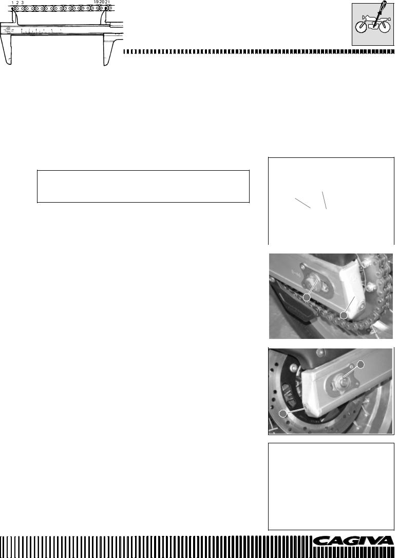
MAINTENANCE
RADIATOR TUBES
• Remove the sump guard protection 5 by unscrewing the two screws 6 indicated in the figure. Push it aside in the direction of the arrow.
Check to see if the radiator tubes are damaged, cracked or leak. If any defect is found, substitute the tubes immediately.
TRANSMISSION CHAIN
Check at 1000 km (or 1 month)
Every 6000 km (or 6 months)
Clean and lubricate every 1000 km.
Visually check the transmission chain for the following defects. Put |
||||
the machine on a jack and a block of wood. Slowly rotate the rear |
||||
wheel by hand with the engine in neutral. |
||||
* Slack pins |
* |
Excessive wear |
|
|
|
||||
* Damaged rollers |
* |
Incorrect chain adjustment |
|
|
|
||||
* Dry or rusty links |
|
|
|
|
* Missing O-rings |
* |
Bent or seized links |
|
|
The chain must be substituted if any one of these defects is found. |
|
|||
|
|
|
|
1 |
|
|
|
|
2 |
|
|
|
|
|
|
|
|
||
Substitute also the crown and pinion wheels when substituting the |
|
|||
transmission chain. |
|
|
|
|
|
|
|
||
CHECK |
|
|
|
|
|
1 |
|||
• Slacken the axle nut 1. |
|
|||
• Completely tighten the chain by adjusting the screw adjusters 2. |
||||
2
•Count 21 pins (20 pitches) of the chain and measure the distance between the two points. If the distance exceeds the operating limits, the chain must be substituted.
Operating limit (20 pitches of the transmission chain):
323 mm
B.21

MAINTENANCE
CHAIN ADJUSTMENT
•Slacken or tighten both chain screw adjusters 1 until the chain reaches a slack of 25-35 mm in the central position of the chain between the crown and pinion. The marks A on both screw adjusters must be in the same position of the scale to ensure the correct alignment of the wheel.
•To make accurate adjustments, place the machine on the side stand.
•After having correctly adjusted the chain, tighten the axle nut 2 to the specified torque.
•Recheck the chain slack after having tightened the axle nut 2.
Torque pressure
Rear axle nut: 63,7÷ 68,6 N·m (6,5 ÷ 7 kg-m)
1 
CLEANING AND LUBRICATION
•Wash the chain with kerosene. If the chain tends to rust quickly, shorten the maintenance intervals.
Do not use Trichloroethylene, petrol or other similar liquids. These liquids possess an excessive solvent power and more importantly, can damage the O-rings that keep the grease inside the spaces between the rollers and pins. Long life of the chain depends on the presence of grease in these spaces.
•After having washed and dried the chain, grease it with high viscosity engine oil or with lubricants specifically produced for chains with O-rings.
2
A
B.22
 Loading...