


MICROMMAC 24T
Table of contents
 Loading...
MICROMMAC-22T/24T/42T/44T
STA CKABLE T OKEN RING
INTELLIGENT HUBS
USER’S GUIDE

iii
NOTICE
Cabletron Systems reserves the right to make changes in specifications and other
information contained in this document without prior notice. The reader should in all cases
consult Cabletron Systems to determine whether any such changes have been made.
The hardware, firmware, or software described in this manual is subject to change without
notice.
IN NO EVENT SHALL CABLETRON SYSTEMS BE LIABLE FOR ANY
INCIDENTAL, INDIRECT, SPECIAL, OR CONSEQUENTIAL DAMAGES
WHATSOEVER (INCLUDING BUT NOT LIMITED TO LOST PROFITS) ARISING
OUT OF OR RELATED TO THIS MANUAL OR THE INFORMATION CONTAINED
IN IT, EVEN IF CABLETRON SYSTEMS HAS BEEN ADVISED OF, KNOWN, OR
SHOULD HAVE KNOWN, THE POSSIBILITY OF SUCH DAMAGES.
© Copyright March 1996 by:
Cabletron Systems, Inc.
P.O. Box 5005, Rochester, NH 03866-5005
All Rights Reserved
Printed in the United States of America
Order Number: 9031320 March 1996
MicroMMAC-22T , 24T , 42T, 44T, BRIM, and TPIM are trademarks of Cabletron Systems,
Inc.
SPECTRUM, LANVIEW, and Remote LANVIEW are registered trademarks of Cabletron
Systems, Inc.
IBM is a registered trademark of International Business Machines Corporation.
DEC, VT200, and VT300 are trademarks of Digital Equipment Corporation.
CompuServe is a trademark of Compuserve, Inc.
Printed On
Recycled Pa
per

NOTICE
iv
FCC NOTICE
This device complies with Part 15 of the FCC rules. Operation is subject to the following
two conditions: (1) this device may not cause harmful interference, and (2) this device must
accept any interference received, including interference that may cause undesired
operation.
NOTE: This equipment has been tested and found to comply with the limits for a Class A
digital device, pursuant to Part 15 of the FCC rules. These limits are designed to provide
reasonable protection against harmful interference when the equipment is operated in a
commercial environment. This equipment uses, generates, and can radiate radio frequency
energy and if not installed in accordance with the operator’s manual, may cause harmful
interference to radio communications. Operation of this equipment in a residential area is
likely to cause interference in which case the user will be required to correct the
interference at his own expense.
WARNING: Changes or modifications made to this device which are not expressly
approved by the party responsible for compliance could void the user’ s authority to operate
the equipment.
DOC NOTICE
This digital apparatus does not exceed the Class A limits for radio noise emissions from
digital apparatus set out in the Radio Interference Regulations of the Canadian Department
of Communications.
Le présent appareil numérique n’émet pas de bruits radioélectriques dépassant les limites
applicables aux appareils numériques de la class A prescrites dans le Règlement sur le
brouillage radioélectrique édicté par le ministère des Communications du Canada.
VCCI NOTICE
This equipment is in the 1st Class Category (information equipment to be used in
commercial and/or industrial areas) and conforms to the standards set by the Voluntary
Control Council for Interference by Information Technology Equipment (VCCI) aimed at
preventing radio interference in commercial and/or industrial areas.
Consequently, when used in a residential area or in an adjacent area thereto, radio
interference may be caused to radios and TV receivers, etc.
Read the instructions for correct handling.
NEED JAP ANESE GRAPHIC TEXT HERE
BEFORE RELEASE

NOTICE
v
CABLETRON SYSTEMS, INC. PROGRAM
LICENSE AGREEMENT
IMPORTANT: Before utilizing this product, carefully read this License Agreement.
This document is an agreement between you, the end user, and Cabletron Systems, Inc.
(“Cabletron”) that sets forth your rights and obligations with respect to the Cabletron
software program (the “Program”) contained in this package. The Program may be
contained in firmware, chips or other media. BY UTILIZING THE ENCLOSED
PRODUCT, YOU ARE AGREEING TO BECOME BOUND BY THE TERMS OF THIS
AGREEMENT, WHICH INCLUDES THE LICENSE AND THE LIMITATION OF
WARRANTY AND DISCLAIMER OF LIABILITY. IF YOU DO NOT AGREE TO THE
TERMS OF THIS A GREEMENT , PR OMPTL Y RETURN THE UNUSED PRODUCT T O
THE PLACE OF PURCHASE FOR A FULL REFUND.
CABLETRON SOFTWARE PROGRAM LICENSE
1. LICENSE.
Y ou have the right to use only the one (1) cop y of the Program provided in
this package subject to the terms and conditions of this License Agreement.
You may not copy, reproduce or transmit any part of the Program except as permitted by
the Copyright Act of the United States or as authorized in writing by Cabletron.
2. O
THER RESTRICTIONS. You may not reverse engineer, decompile, or disassemble
the Program.
3.
APPLICABLE LAW. This License Agreement shall be interpreted and governed
under the laws and in the state and federal courts of New Hampshire. You accept the
personal jurisdiction and venue of the New Hampshire courts.
EXCLUSION OF WARRANTY AND DISCLAIMER
OF LIABILITY
1. EXCLUSION OF
WARRANTY. Except as may be specifically provided by
Cabletron in writing, Cabletron makes no warranty, expressed or implied, concerning the
Program (including Its documentation and media).
CABLETRON DISCLAIMS ALL WARRANTIES, OTHER THAN THOSE SUPPLIED
TO YOU BY CABLETRON IN WRITING, EITHER EXPRESS OR IMPLIED,
INCLUDING BUT NOT LIMITED TO IMPLIED WARRANTIES OF
MERCHANTABLITY AND FITNESS FOR A PARTICULAR PURPOSE, WITH
RESPECT TO THE PROGRAM, THE ACCOMPANYING WRITTEN MATERIALS,
AND ANY ACCOMPANYING HARDWARE.

NOTICE
vi
2. NO LIABILITY FOR CONSEQ
UENTIAL DAMAGES. IN NO EVENT SHALL
CABLETRON OR ITS SUPPLIERS BE LIABLE FOR ANY DAMAGES
WHATSOEVER (INCLUDING, WITHOUT LIMITATION, DAMAGES FOR LOSS OF
BUSINESS, PROFITS, BUSINESS INTERRUPTION, LOSS OF BUSINESS
INFORMATION, SPECIAL, INCIDENTAL, CONSEQUENTIAL, OR RELIANCE
DAMA GES, OR O THER LOSS) ARISING OUT OF THE USE OR IN ABILITY T O USE
THIS CABLETRON PRODUCT, EVEN IF CABLETRON HAS BEEN ADVISED OF
THE POSSIBILITY OF SUCH DAMAGES. BECAUSE SOME STATES DO NOT
ALLOW THE EXCLUSION OR LIMITATION OF LIABILITY FOR
CONSEQUENTIAL OR INCIDENTAL DAMAGES, OR ON THE DURATION OR
LIMITATION OF IMPLIED WARRANTEES IN SOME INSTANCES THE ABOVE
LIMITATIONS AND EXCLUSIONS MAY NOT APPLY TO YOU.
UNITED STATES GOVERNMENT RESTRICTED
RIGHTS
The enclosed product (a) was developed solely at pri vate expense; (b) contains “restricted
computer software” submitted with restricted rights in accordance with Section 52227-19
(a) through (d) of the Commercial Computer Software - Restricted Rights Clause and its
successors, and (c) in all respects is proprietary data belonging to Cabletron and/or its
suppliers.
For Department of Defense units, the product is licensed with “Restricted Rights” as
defined in the DoD Supplement to the Federal Acquisition Regulations, Section
52.227-7013 (c) (1) (ii) and its successors, and use, duplication, disclosure by the
Government is subject to restrictions as set forth in subparagraph (c) (1) (ii) of the Rights
in Technical Data and Computer Software clause at 252.227-7013. Cabletron Systems,
Inc., 35 Industrial Way. Rochester, New Hampshire 03866

vii
CONTENTS
CHAPTER 1 INTRODUCTION
1.1 CONTENTS OVERVIEW. . . . . . . . . . . . . . . . . . . . . . . . . .1-1
1.2 MicroMMAC-T OVERVIEW . . . . . . . . . . . . . . . . . . . . . . . .1-2
1.3 MicroMMAC-T FEATURES . . . . . . . . . . . . . . . . . . . . . . . .1-3
1.4 STACKABLE CAPABILITIES . . . . . . . . . . . . . . . . . . . . . . .1-8
1.5 BRIDGING/ROUTING CAPABILITIES. . . . . . . . . . . . . . . .1-9
1.5.1 SNA/WAN Integration. . . . . . . . . . . . . . . . . . . . . .1-10
1.6 REMOTE MANAGEMENT CAPABILITIES . . . . . . . . . . .1-10
1.7 TELNET CAPABILITIES . . . . . . . . . . . . . . . . . . . . . . . . .1-10
1.8 RECOMMENDED READING. . . . . . . . . . . . . . . . . . . . . .1-11
1.9 GETTING HELP. . . . . . . . . . . . . . . . . . . . . . . . . . . . . . . .1-11
CHAPTER 2 REQUIREMENTS/SPECIFICATIONS
2.1 CABLE SPECIFICATIONS. . . . . . . . . . . . . . . . . . . . . . . . .2-1
2.1.1 UTP Cable Specifications . . . . . . . . . . . . . . . . . . .2-2
2.1.2 STP Cable Specifications. . . . . . . . . . . . . . . . . . . .2-4
2.1.4 Single Mode Fiber Optic Cable Specifications. . . .2-7
2.2 CABLE RECOMMENDATIONS/TROUBLESHOOTING . .2-8
2.3 COM PORT SPECIFICATIONS. . . . . . . . . . . . . . . . . . . . .2-9
2.4 TPIM SPECIFICATIONS . . . . . . . . . . . . . . . . . . . . . . . . .2-10
2.5 GENERAL SPECIFICATIONS. . . . . . . . . . . . . . . . . . . . .2-15
2.5.1 Power Supply Requirements . . . . . . . . . . . . . . . .2-16
2.5.2 Environmental Requirements. . . . . . . . . . . . . . . .2-16
2.5.3 Safety. . . . . . . . . . . . . . . . . . . . . . . . . . . . . . . . . .2-16
2.5.4 Physical . . . . . . . . . . . . . . . . . . . . . . . . . . . . . . . .2-16
2.5.5 Service. . . . . . . . . . . . . . . . . . . . . . . . . . . . . . . . .2-17
CHAPTER 3 INSTALLATION
3.1 UNPACKING THE MicroMMAC-T . . . . . . . . . . . . . . . . . . .3-1
3.2 ATTACHING THE STRAIN RELIEF BRACKET . . . . . . . . .3-1
3.3 INSTALLING THE MicroMMAC-T . . . . . . . . . . . . . . . . . . .3-2
3.3.1 Rack-Mounting the MicroMMAC-T. . . . . . . . . . . . .3-2
3.3.2 Wall-Mounting the MicroMMAC-T . . . . . . . . . . . . .3-3
3.3.3 Free-Standing Installation . . . . . . . . . . . . . . . . . . .3-5
3.4 CONNECTING TO A POWER SOURCE. . . . . . . . . . . . . .3-5

CONTENTS
viii
3.5 RESETTING THE MICROMMAC-T. . . . . . . . . . . . . . . . . . 3-5
3.6 SETTING THE RING SPEED . . . . . . . . . . . . . . . . . . . . . .3-6
3.7 SETTING THE NVRAM SWITCH . . . . . . . . . . . . . . . . . . .3-7
3.8 CONNECTING LOBE PORT CABLING . . . . . . . . . . . . . .3-8
3.9 INSTALLING TPIM MODULES . . . . . . . . . . . . . . . . . . . . 3-12
3.9.1 Setting Phantom and RI/RO Switches. . . . . . . . . 3-13
3.9.2 TPIM Installation . . . . . . . . . . . . . . . . . . . . . . . . .3-14
3.9.3 Connecting STP Segments . . . . . . . . . . . . . . . . .3-15
3.9.4 Connecting Twisted Pair Segments . . . . . . . . . . .3-16
3.9.5 Connecting Fiber Optic Link Segments . . . . . . . . 3-17
3.10 CHECKING THE INSTALLATION . . . . . . . . . . . . . . . . . .3-19
CHAPTER 4 LOCAL MANAGEMENT
4.1 MANAGEMENT TERMINAL REQUIREMENTS . . . . . . . .4-1
4.1.1 Attaching the Management Terminal . . . . . . . . . . .4-2
4.1.2 Management Terminal Setup Parameters . . . . . . .4-2
4.1.3 Modem Cable Configuration and Setup. . . . . . . . .4-3
4.2 ACCESSING LOCAL MANAGEMENT . . . . . . . . . . . . . . .4-4
4.2.1 Accessing Local Management via Telnet. . . . . . . .4-5
4.2.2 Accessing Local Management from a Modem. . . .4-6
4.3 USING LOCAL MANAGEMENT . . . . . . . . . . . . . . . . . . . .4-6
4.3.1 Working with Local Management Screens. . . . . . .4-7
4.3.2 The SYSTEM LEVEL Screen . . . . . . . . . . . . . . . . 4-9
4.3.3 The SNMP COMMUNITY NAMES Screen . . . . .4-15
4.3.4 The SNMP TRAPS Screen . . . . . . . . . . . . . . . . .4-17
4.3.5 The RING SECURITY Screen. . . . . . . . . . . . . . . 4-18
4.3.6 The DEVICE STATISTICS Screen. . . . . . . . . . . . 4-23
4.3.7 The CHASSIS STATUS VIEW Screen. . . . . . . . . 4-28
4.3.8 The COMPONENT STATUS Screen . . . . . . . . . .4-35
4.3.9 The MIB NAVIGATOR Screen . . . . . . . . . . . . . . .4-36
4.3.10 The FLASH DOWNLOAD Screen . . . . . . . . . . . .4-40
CHAPTER 5 TROUBLESHOOTING
5.1 USING LANVIEW LEDs . . . . . . . . . . . . . . . . . . . . . . . . . . 5-1
5.2 USING THE LCD DISPLAY . . . . . . . . . . . . . . . . . . . . . . . .5-2
5.2.1 Static System Messages . . . . . . . . . . . . . . . . . . . .5-3
5.2.2 Alarm Messages . . . . . . . . . . . . . . . . . . . . . . . . . . 5-4
5.2.3 Unsaved Initialization Messages . . . . . . . . . . . . . .5-5

CONTENTS
ix
5.2.4 Saved System Messages. . . . . . . . . . . . . . . . . . . .5-6
5.3 VIEWING POWER UP DIAGNOSTIC TESTS. . . . . . . . . .5-7
1-1
CHAPTER 1
INTRODUCTION
Welcome to the Cabletron Systems
MicroMMAC-22T/-24T/-42T/
-44T Stackable Token Ring Intelligent Hub User’s Guide
. This manual
provides installation instructions, network requirements, reference
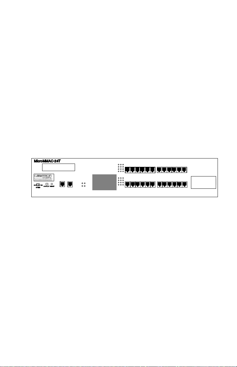
information, and operating instructions for the MicroMMAC-T (Figure
1-1) family of stackable hubs. Installing the MicroMMAC-T requires
familiarity with the physical layer components of Token Ring (IEEE
802.5) data communications networks.
NOTE
: Unless otherwise specified, this manual uses the term
MicroMMAC-T to collectively refer to the MicroMMAC-22T, the
MicroMMAC-24T, the MicroMMAC-42T, and the MicroMMAC-44T.
.
Figure 1-1. The MicroMMAC-T
1.1 CONTENTS OVERVIEW
This manual contains the following information:
Chapter 1,
Introduction
, outlines the contents of this manual and
describes features of the MicroMMAC-T and its add-on components. It
also lists sources where more information on Token Ring network
implementation can be found.
Chapter 2,
Requirements/Specifications
, describes cabling requirements,
network guidelines, and MicroMMAC-T operating specifications.
Chapter 3,
Installation,
contains MicroMMAC-T installation instructions
and discusses network connections using various media types. This
chapter includes instructions for setting the Ring Speed Switch, the Reset
Switch, the NVRAM Switch, and the TPIM Phantom Switch. It also
RO
TOKEN RING HUB
WITH
LANVIEW®
SUPPORTING 100 OHM UTP CABLE
MicroMMAC-24T
RESET
CPU
ACT
MGMT
16 Mb/s
COM 1COM 2
DISPLAY
SPEED
16M4M
TPIM
6 5 4 3 2 1
18 17 16 15 14 13
24 23 22 21 20 19
12 11 10 9 8 7
RI
LCD
TPIM
Slot
Ring Out

INTRODUCTION
1-2
describes how to install a TPIM and concludes with installation check-out
instructions.
Chapter 4,
Local Management
, explains how to set up and use a
management terminal and a modem to access Local Management.
Chapter 5,
Troubleshooting
, explains how to monitor the operation
performance of the MicroMMAC-T using LANVIEW® LEDs and LCD’ s.
It also explains how to access POWER UP diagnostic test information.
1.2 MicroMMAC-T OVERVIEW
The MicroMMAC-T is an intelligent, stackable Multi-Media Access
Center providing connectivity and SNMP management for up to 255
Token Ring users (Local Management for up to 120 Token Ring users) in
remote office environments. The MicroMMAC-T can be used in
conjunction with Cabletron’s STH HubSTACK series of stackable
non-intelligent hubs.
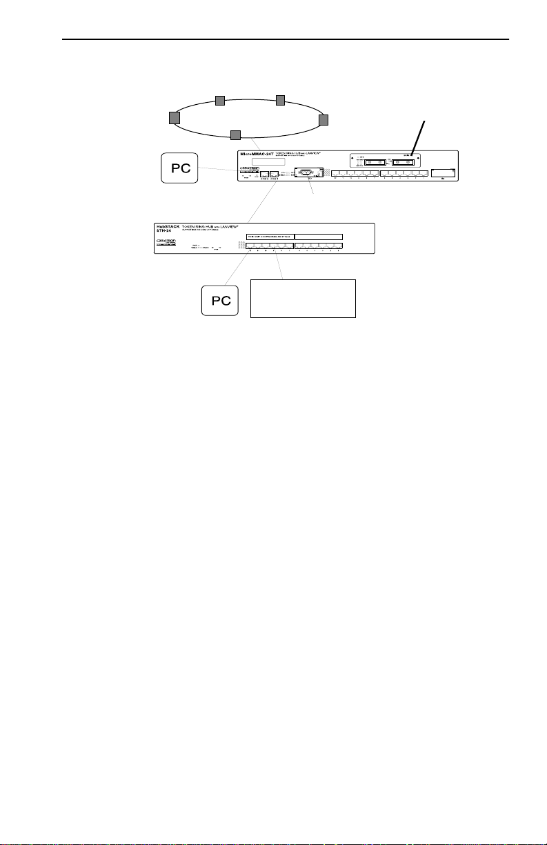
Figure 1-2 illustrates a typical MicroMMAC-T configuration scenario.
Attachable Bridge/Routing Interface Modules (BRIMs), incorporated as
seamless entities within the MicroMMAC-T , provide connecti vity not only
to standard Token Rings but also to Ethernet, FDDI, ATM, and WAN
environments, depending upon the BRIM types used.
T oken Ring Port Interface Modules (TPIMs) attachable at the Ring In/Ring
Out (RI/RO) ports provide connecti vity and expanded trunk connections to
a range of Token Ring media: Unshielded Twisted Pair (UTP), Shielded
Twisted Pair (STP), and Fiber.
By installing Cabletron’s MicroSNAC daughterboard in the
MicroMMAC-T, you can consolidate SNA/SDLC, BSC, LAN, and WAN
connectivity into a single unit.
T elnet support provides easy access to Local Management tools from any
TCP/IP based node on the network.
The MicroMMAC-T complies with the IEEE 802.5 standard and is fully
IBM Token Ring compatible. The remainder of this chapter discusses
MicroMMAC-T features in greater detail.
INTRODUCTION
1-3
Figure 1-2. Typical MicroMMAC-T Configuration Scenario
All MicroMMAC-Ts are functionally and physically identical except for
the number and type of their Trunk Connection Unit (TCU) lobe ports. The
following MicroMMAC-T configurations are available:
•
MicroMMAC-22T
: twelve active RJ45 TCU lobe ports that support
category 3, 4, and 5 UTP cabling.
•
MicroMMAC
24T
: twenty-four active RJ45 TCU lobe ports that
support category 3, 4, and 5 UTP cabling.
•
MicroMMAC-42T
: twelve active RJ45 TCU lobe ports that support
IBM Type 1, 2, 6, and 9 STP cabling.
•
MicroMMAC-44T
: twenty-four active RJ45 TCU lobe ports that
support IBM Type 1, 2, 6, and 9 STP cabling.
1.3 MicroMMAC-T FEATURES
NOTE
: Call your Cabletron Sales representative to order the 12-port
upgrade kit, the MicroSNAC device, BRIMs, TPIMs, interface cables, and
other accessories for the MicroMMAC-T.
SDLC
TOKEN RING
Telnet
UTP
WORKSTATION

INTRODUCTION
1-4
Active TCU Ports
The active TCU ports regenerate, reshape, and filter the incoming signal,
permitting UTP lobe cable lengths of up to
120 meters
and STP lobe cable
lengths up to
150 meters
at 16 Mbps ring speed. The MicroMMAC-22T
and the MicroMMAC-42T can be upgraded in the field using the Cabletron
UTP and STP 12-port upgrade kits.
Cable Signal Polarity
Differential Manchester encoding is used for each concentrator module
TCU port. This permits passing data regardless of receive link polarity.
NOTE
: The MicroMMAC-T is not affected by the reversed polarity
condition. If, however, such a condition is discovered, the segment should
be removed fr om the network and wired corr ectly to avoid problems during
future network operations. Refer to Section 3.8 for cable pinouts
specifications
Speed Fault Protection
If a station attempts to insert into a ring port at a different speed from the
one set on the MicroMMAC-T, that port is automatically bypassed to
prevent the ring from beaconing. The Lobe Port Status LED blinks red (for
more information, see Section 5.1, USING LANVIEW LEDs) to indicate
that the port with the speed fault is being bypassed.
Local Management
Local Management provides you with the ability to manage the
MicroMMAC-T and all of its attached segments, including most BRIMs
and the MicroSNAC device. The CR BRIM-W/T and the MicroSNAC
provide their own configuration firmware.
Access Local Management by connecting an actual or emulated Digital
Equipment Corporation VT100™ series terminal to the MicroMMA C-T’s
COM 1 port or the COM 2 port. To view diagnostic test information from
a display terminal, use the COM 2 port.
Token Ring Port Interface Modules (TPIMs)
TPIMs are modular connector cards used for expanding trunk connections
to a range of Token Ring media. TPIMs have embedded repeaters that

INTRODUCTION
1-5
re-time all data. Cabletron offers a variety of TPIMs for RI/RO trunk
connections as shown in Table 1-1.
Ring Speed Switch
Use the Ring Speed Switch to select either 4 or 16 Mbps ring speed.
Flash EEPROM
The firmware image on the MicroMMAC-T can be upgraded by Flash
EEPROM downloads via Cabletron System’s Remote
LANVIEW/Windows version 2.3 or later, or via any server supporting
BOOTP or TFTP protocols.
LANVIEW LEDs
Cabletron Systems’ LANVIEW LEDs, located on the face of the
MicroMMAC-T, provide an effective monitoring and troubleshooting tool
to help diagnose power failures, RI/R O status, cable faults, ring speed, link
problems, and network activity. See Section 5.1 for information about
using LEDs.
Cabletron’s Distributed LAN Monitor Mode
To manage a network that includes multiple subnets, remote network
management stations need to query multiple management devices,
increasing the data traffic on the network. Network managers can reduce
the amount of management related traffic by setting the MicroMMAC-T
into Distributed LAN Monitor mode via a remote management package.
The MicroMMAC-T in DLM mode will collect management data from the
Table 1-1. TPIMs
TPIM Media T ype Connector
TPIM-T1 Shielded T wisted Pair DB9
TPIM-T2 Unshielded T wisted Pair RJ45
TPIM-T4 Shielded T wisted Pair RJ45
TPIM-F2 Multimode Fiber Optic ST
TPIM-F3 Single mode Fiber Optic ST

INTRODUCTION
1-6
numerous management devices and serve as their management data
representative. The network management station then has to query only
one management device, the MicroMMAC-T in DLM mode, to access
management data for all management devices on the network.
Consult your network manager for DLM setup.
COM Port Applications
Both of the front panel COM ports are factory-configured to support Local
Management connections. Select among configuration options for Local
Management, Uninterruptible Power Supplies (UPS), the Serial Line
Internet Protocol (SLIP), and modems.
LCD and LCD Display Button
MicroMMAC-T’s front panel LCD used in conjunction with the LCD
display button provides you with comprehensiv e system-lev el information
such as power-up diagnostics, FLASH image re vision levels, IP addresses,
and error alerts. See Section 5.2 for more information.
Reset Button
The Reset button on the front panel initializes the processor when pressed.
The information contained in NVRAM is retained after initialization. See
Section 3.5 for more information.
MIB Support
The MicroMMAC-T provides access to the following Management
Information Bases:
Standard MIBs
• MIB-2 (RFC 1231)
• IEEE RMON MIB (RFC 1271)
• RMON Extensions for Token Ring (RFC 1513)
Cabletron Enterprise MIBs
• Download
• MIB-II Extensions

INTRODUCTION
1-7
• Token Ring FNB (Flexible Network Bus)
• DOT 5 Logical and Physical
• UPS (Uninterruptible Power Supply)
• Device
• DLM (Distributed LAN Monitor)
• PIC MIB (Product Information Chip MIB)
• Chassis MIB
RMON MIB Support
The MicroMMAC-T supports the RMON MIB RFC 1271/1513 Token
Ring Extensions shown in Table 1-2.
Table 1-2. RMON MIB RFC 1271/1513 Support
Group Subgroup Section
Statistics
rmon 1
Token Ring ML Stats Table
Token Ring P Stats Table
statistics 2
statistics 3
History
rmon 2
History Control Table
Token Ring ML History Table
Token Ring P History Table
history 1
history 3
history 4
Alarm
rmon 3
Alarm T able alarm 1
Host
rmon 4
Host Control Table
Host T able
Host Time Table
hosts 1
hosts 2
hosts 3
HostTopN
rmon 5
HostTopN Control Table
HostT opN Table
hostTopN 1
hostTopN 2
Matrix
rmon 6
Matrix Control Table
Matrix SD Table
Matrix DS Table
Matrix 1
Matrix 2
Matrix 3

INTRODUCTION
1-8
1.4 STACKABLE CAPABILITIES
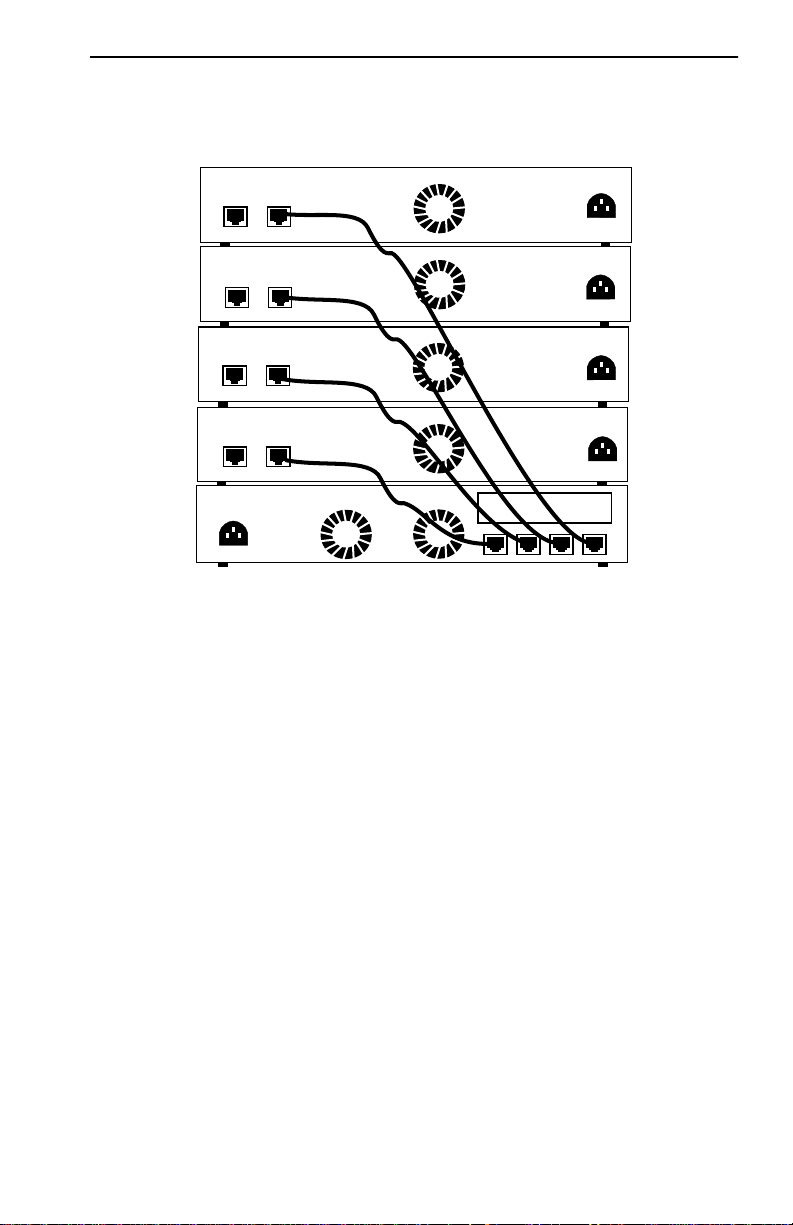
The MicroMMAC-T can be stacked with up to four HubSTACK STH
series non-intelligent hubs as shown in Figure 1-3. Four connectors are
available on the back panel of the MicroMMAC-T for connecting STH
12/24 type non-intelligent hubs. The MicroMMAC-T provides complete
management, including full packet and error statistics for the entire stack,
individual device, or individual port.
It is not necessary to power-of f the MicroMMA C-T to add or remove hubs
from the stack.
Event
rmon 9
Event Table
Log T able
event 1
event 2
Token Ring
rmon 10
Ring Station Control Table
Ring Station Table
Ring Station Order Table
Ring Station Config Control Table
Ring Station Config Table
Source Routing Stats Table
Token Ring 1
Token Ring 2
Token Ring 3
Token Ring 4
Token Ring 5
Token Ring 6
Table 1-2. RMON MIB RFC 1271/1513 Support (Cont.)
Group Subgroup Section
INTRODUCTION
1-9
Figure 1-3. Typical Stackable Configuration
NOTE
: Token Ring HubSTACK Interface cables, which are used to
connect between the MicroMMAC-T and stacked STH hubs, are not
included with the MicroMMAC-T.
1.5 BRIDGING/ROUTING CAPABILITIES
A slot on the back panel of the unit provides installation access for BRIMs
to the hub. MicroMMA C-T management systems treat the installed BRIM
and the hub as a single entity. Cabletron offers the BRIMs listed in
Table 1-3.
REAR VIEW
MicroMMAC Managing 4 Non-Intelligent Hubs
HubSTACK
STH-24
MicroMMAC-24T
TOKEN RING HUB
WITH
LANVIEW®
BRIM Slot
STACK
RESERVED
STACK5STACK4STACK3STACK2
STACK
RESERVED
RESERVED
STACK
STACK
RESERVED
HubSTACK
STH-24
HubSTACK
STH-24
HubSTACK
STH-24

INTRODUCTION
1-10
.
1.5.1 SNA/WAN Integration
The MicroSNA C add-on daughterboard provides two ports, both of which
can be used to provide conv ersion from SNA/SDLC or BSC links to LLC2.
The MicroSNAC can operate in a converter mode or as a WAN
concentrator.
1.6 REMOTE MANAGEMENT CAPABILITIES
The MicroMMAC-T may be managed through any Simple Network
Management Protocol (SNMP) software. Cabletron Systems offers the
following remote management packages:
• Cabletron Systems SPECTRUM
®
• Cabletron Systems Remote LANVIEW
®
/Windows™
• Cabletron Systems Remote SPECTRUM
®
Portable Management
Applications
1.7 TELNET CAPABILITIES
The MicroMMAC -T supports Telnet, which allows any TCP/IP based
node on the network to establish a Local Management session with the
Table 1-3. BRIMs
BRIM Description
BRIM-E6 Ethernet Connection
BRIM-W6 Wide Area Network (Full or Fractional T1; 56k DDS)
BRIM-A6 Asynchronous Transfer Mode Connection
BRIM-T6 Token Ring Connection
CR BRIM-W/T Cisco WAN BRIM for Token Ring
BRIM-FO Fiber Distributed Data Interface Connection

INTRODUCTION
1-11
module. This feature complements the remote SNMP management and
allows for quick hub configuration changes or checks.
1.8 RECOMMENDED READING
The following publications provide more information on Token Ring
network implementation.
Local Area Networks, Token Ring Access Method
, IEEE Standard 802.5
(1989)
Commercial Building Wiring Standard, EIA/TIA-568
LAN Troubleshooting Handbook
, Mark Miller (1989, M&T Publishing)
1.9 GETTING HELP
For additional support related to the Cabletron Systems MicroMMAC-T,
or for any questions, comments, or suggestions concerning this manual,
contact Cabletron Systems Technical Support:
By phone. . . . . . . . . . . . . . . . . . (603) 332-9400
Monday-Friday; 8am - 8pm EST
By CompuServe
®
. . . . . . . . . . . GO CTRON from any ! prompt
By Internet mail . . . . . . . . . . . . support@ctron.com
By BBS. . . . . . . . . . . . . . . . . . . (603) 337-3750
By mail . . . . . . . . . . . . . . . . . . . Cabletron Systems, Inc.
P.O. Box 5005
Rochester, NH 03866-5005
2-1
CHAPTER 2
REQUIREMENTS/SPECIFICATIONS
Read this chapter prior to installing the MicroMMAC-T. It contains
operating specifications and requirements for power and cabling. T o obtain
satisfactory performance from this equipment, networks must meet the
requirements and conditions specified in this chapter. Failure to follow
these guidelines may result in poor network performance.
2.1 CABLE SPECIFICATIONS
Token Ring architecture provides for a set of Trunk Coupling Units
(TCUs) connected by trunk cabling. To extend the trunk cabling, install
TPIMs into the MicroMMAC-T’s RI/RO ports. TPIMs have embedded
repeaters and provide trunk connections for UTP, STP, Multimode Fiber,
and Single Mode Fiber cabling.
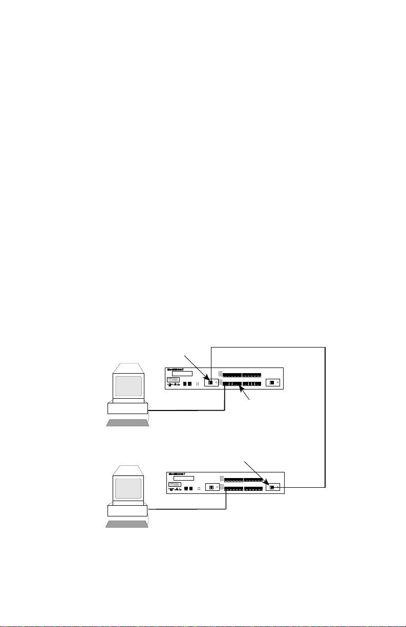
Attach stations to the TCU lobe ports with lobe cabling. Figure 2-1 shows
a typical ports to cables configuration.
Figure 2-1. MicroMMAC-T Ports/Cables
Trunk Cabling
Token Ring Station
DISPLAY
TOKEN RING HUB WITH LANVIEW®
SUPPORTING 100 OHM STP CABLE
MicroMMAC-24T
RESET
CPU
ACT
MGMT
16 Mb/s
COM 1COM 2
DISPLAY
SPEED
16M4M
6 5 4 3 2 1
18 17 16 15 14 13
24 23 22 21 20 19
12 11 10 9 8 7
DISPLAY
TOKEN RING HUB WITH LANVIEW®
SUPPORTING 100 OHM STP CABLE
MicroMMAC-24T
RESET
CPU
ACT
MGMT
16 Mb/s
COM 1COM 2
DISPLAY
SPEED
16M4M
6 5 4 3 2 1
18 17 16 15 14 13
24 23 22 21 20 19
12 11 10 9 8 7
Lobe Cabling
TCU Lobe Ports
Ring Out TPIM
Ring In TPIM
RO
RO RI
RI

REQUIREMENTS/SPECIFICATIONS
2-2
2.1.1 UTP Cable Specifications
The MicroMMAC-22T and MicroMMAC-24T lobe ports and the
TPIM-T2 support voice grade Unshielded Twisted Pair (UTP) cable, as
described in specifications for EIA/TIA TSB 568 and IBM Type 3 cable.
UTP consists of four pairs of 24 AWG solid wire for data or voice
communication and is typically used to wire cable runs within building
walls. In some installations, existing UTP building wiring can be used for
Token Ring cabling. UTP cable must conform to the limits shown in
Table 2-1.
WARNING
: DO NOT
connect UTP cabling to any non-Token Ring
network conductors (telephone, etc.) or ground. If in doubt, test wiring
before using. The voltages used in UTP telephone circuits present a shock
hazard and can damage Token Ring equipment when connected to Token
Ring cabling.
The increased popularity and cost advantages of UTP cable have driven
refinements in UTP cable design. Better grades of UTP cable, known as
supergrade or level 4, provide improved transmission characteristics and
may allow operation at 16 Mbps on longer lobe cables.
Attenuation and Impedance
The values listed in Figure 2-1 include the maximum attenuation of the
cables, connectors, patch panels, and reflection losses due to impedance
mismatches in the segment.
Table 2-1. UTP Voice Grade and Category 3 Specifications
Frequency Impedance Attenuation
1 MHz 100Ω ±15% <26 dB/km (8 dB/1000 ft)
4 MHz 100Ω ±15% <56 dB/km (16 dB/1000 ft)
10 MHz 100Ω ±15% <98 dB/km (30 dB/1000 ft)
16 MHz 100Ω ±15% <131 dB/km (40 dB/1000 ft)

REQUIREMENTS/SPECIFICATIONS
2-3
Maximum Lobe Lengths
Lobe length is the physical length of the cable connecting a station to its
TCU port at the MicroMMAC-T. Table 2-2 lists the maximum lobe cable
length for ring speeds of 4 and 16 Mbps. The values listed refer to total
lengths made up of UTP cable only.
Type 3 Media Filters
A Type 3 Media Filter is required when connecting a UTP lobe segment
from a MicroMMAC-22T or MicroMMAC-24T to a station supporting
STP cabling. Cabletron Systems offers the following T ype 3 Media Filters:
• TRMF , RJ45 (UTP) connector to 10-inch DB9 (STP) cable with
LANVIEW
• TRMF-2, RJ45 (UTP) connector to DB9 (STP) connector
Maximum Number of Stations
When UTP lobe cabling is used in any ring segment, the number of ring
stations supported by the MicroMMAC-T is limited to 150, regardless of
the operating ring speed.
Table 2-2. UTP Maximum Lobe Lengths
UTP Cable Type Maximum Lobe Length
4 Mbps 16 Mbps
Category 3 200 meters 100 meters
(656 feet) (328 feet)
Category 4 200 meters 100 meters
(656 feet) (328 feet)
Category 5 250 meters 120 meters
(820 feet) (394 feet)

REQUIREMENTS/SPECIFICATIONS
2-4
2.1.2 STP Cable Specifications
MicroMMACs 42T and 44T and TPIMs T1 and T4 support IBM Type 1,
2, 6, and 9 STP cabling as described below:
• IBM T ype 1: Two STP lengths of 22 AWG solid wire for data. Used
for the longest cable runs within building walls of buildings.
• IBM T ype 2: Similar to Type 1 data cable, but having four additional
UTP lengths of 22 AWG solid wire carried outside of the shield casing.
Typically used for voice communication and often used to wire cable
runs within the walls of buildings.
• IBM T ype 6: Two STP lengths of 26 AWG stranded wire for data.
Used in patch panels or to connect devices to/from wall jacks.
Attenuation for Type 6 cable is 3/2 x Type 1 cable (66 m of Type 6
=100 meters of Type 1).
• IBM T ype 9: Similar to Type 1, but uses 26 AWG solid wire.
Attenuation for Type 9 cable is 3/2 x Type 1 cable (66 m of Type 9
= 100 meters of Type 1).
Attenuation and Impedance
The attenuation values shown in Table 2-3 include the attenuation of the
cables, connectors, patch panels, and reflection losses due to impedance
mismatches in the segment
.
Maximum Lobe Lengths
The lobe length is the physical length of the cable connecting a station to
its TCU port at the MicroMMAC-T. Table 2-4 lists the maximum lobe
Table 2-3. STP Cable Specifications
Types Frequency Impedance Attenuation
1 & 2 4 MHz
16 MHz
150Ω + 15%
150Ω + 15%
<22 dB/km (6.7 db/1000 ft.)
<45 dB/km (13.7 db/1000 ft.)
6 & 9 4 MHz
16 MHz
150Ω + 15%
150Ω + 15%
<33 dB/km (10 db/1000 ft.)
<66 dB/km (20 db/1000 ft.)

REQUIREMENTS/SPECIFICATIONS
2-5
cable length for ring speeds of 4 and 16 Mbps. The cable lengths listed in
Table 2-4 refer to total lengths made up of STP cable only
.
Maximum T runk Lengths
The maximum trunk cable length between the MicroMMAC-T and other
active devices is equal to the maximum drive distance as shown in
Table 2-5. For passive devices, the combined length of twice the longest
trunk cable, plus the longest lobe cable attached to the passive ring
segment cannot exceed the Maximum Drive Distance.
Maximum Number of Stations
If only STP lobe cabling is used throughout the ring, the MicroMMAC-T
supports up to 255 ring stations, regardless of ring speed.
Table 2-4. STP Maximum Lobe Lengths
STP Cable Type Ring Speed
4 Mbps 16 Mbps
IBM Types 1 & 2 300 meters 150 meters
(984 feet) (492 feet)
IBM Types 6 & 9 (only for
station to wall jack and patch
panels)
30 meters 30 meters
(99 feet) (99 feet)
Table 2-5. STP Maximum Drive Distance
STP Cable Type Ring Speed
4 Mbps 16 Mbps
IBM Types 1 & 2 770 meters 346 meters
(2525 feet) (1138 feet)
IBM Types 6 & 9 513 meters 230 meters
(1683 feet) (755 feet)

REQUIREMENTS/SPECIFICATIONS
2-6
Mixed Cable Types
If multiple cable types exist in network, compensations must be made for
the different cable attenuations. Type 6 and T ype 9 cables can run only 2/3
the distance of T ype 1. Therefore 10 meters of T ype 1 ≈ 6.6 meters of T ypes
6 and 9.
2.1.3 Multimode Fiber Optic Cable Specifications
Table 2-6 shows specifications for the Multimode Fiber Optic Cable
supported by TPIM-F2
.
Maximum T runk Lengths
The maximum trunk cable length between the MicroMMAC-T and other
active devices is equal to the maximum drive distance as shown in
Table 2-6. For passive devices, the combined length of twice the longest
trunk cable, plus the longest lobe cable attached to the passive ring
segment, must not exceed the Maximum Drive Distance Trunk Length.
Attenuation
Fiber optic cable must be tested with an attenuation test set adjusted for an
850 nm wavelength. This test ensures that a cable’s signal loss is within
acceptable limits. Table 2-6 shows the attenuation for each Multimode
cable type.
Table 2-6. Multimode Fiber Optic Cable Specifications
Cable Type Attenuation Maximum Drive Distance
50/125 µm 13.0 dB or less
The maximum allowable fiber
optic cable length is 2 km
(2187.2 yards). However, IEEE
802.5 specifications allow for a
maximum of 1 km (1093.6
yards).
62.5/125 µm 16.0 dB or less
100/140 µm 19.0 dB or less

REQUIREMENTS/SPECIFICATIONS
2-7
Fiber Optic Budget
The fiber optic delay budget, which determines the fiber optic cable’s
maximum length, should be calculated and taken into consideration in the
network design stage. Fiber optic delay budget is determined by summing
the optical signal loss due to fiber optic cable attenuation, in-line splices,
and fiber optic connectors.
2.1.4 Single Mode Fiber Optic Cable Specifications
Table 2-7 shows specifications for the Single Mode Fiber Optic Cable
supported by TPIM-F3.
Maximum T runk Lengths
The maximum trunk cable length between the MicroMMAC-T and other
active devices is equal to the Maximum Drive Distance as shown in
Table 2-7. For passive devices, the combined length of twice the longest
trunk cable plus the longest lobe cable attached to the passive ring segment
must not exceed the Maximum Drive Distance Trunk Length.
Attenuation
Fiber optic cable must be tested with an attenuation test set adjusted for a
1300 nm wavelength. This test ensures that the cable’ s signal loss is within
an acceptable range of 10 dB or less for any given single mode fiber optic
link.
Table 2-7. Single Mode Fiber Optic Cable Specifications
Cable Type Attenuation Maximum Drive Distance
8/125-12/125 µm 10.0 dB or less The max. allowable fiber optic
cable length is 10 km (10936
yards). However, IEEE 802.5
specs allow for a max. of 1 km
(1093.6 yards).

REQUIREMENTS/SPECIFICATIONS
2-8
Fiber Optic Budget
The fiber optic delay budget, which determines the fiber optic cable’s
maximum length, should be calculated and taken into consideration in the
network design stage. Fiber optic delay budget is determined by summing
the optical signal loss due to fiber optic cable attenuation, in-line splices,
and fiber optic connectors.
2.2 CABLE RECOMMENDATIONS/TROUBLESHOOTING
The following sections describe common cable problems and
recommendations for correcting them.
Crosstalk
Crosstalk is interference caused by signal coupling between different cable
pairs contained within a multi-pair cable bundle. Multi-pair cables should
not be used for UTP lobe cabling. UTP lobe cabling should be dedicated
to carrying T oken Ring traf fic. A v oid mixing T oken Ring signals with other
applications (voice, etc.) within the same cable.
Noise
Noise can be caused by crosstalk or externally imposed impulses. If
noise-induced errors are suspected, ensure that the electrical wiring in the
area is properly wired and grounded and/or try re-routing cabling away
from potential noise sources (motors, switching equipment, fluorescent
lighting, high amperage equipment).
Temperature
The attenuation of PVC-insulated cable varies significantly with
temperature. Check the cable manufacturer’ s specifications. Plenum-rated
cables are strongly recommended in areas where temperatures exceed
40˚C. Under such conditions, plenum-rated cables ensure that cable
attenuation remains within specifications.

REQUIREMENTS/SPECIFICATIONS
2-9
Other Considerations
In addition to complying with the preceding cable specifications, the
following recommendations should be followed to minimize errors and
obtain optimum performance from the network:
• UTP cabling should be free of splices, stubs, or bridged taps.
• Maintain a two punch-down block limit between TCU ports and w all
outlets.
• Properly ground metal troughs, ducts, etc. carrying Token Ring
signals.
• Avoid routing Token Ring signals near copper cables that exit a
building or are susceptible to lightning strikes and power surges.
• UTP cables containing Token Ring signals should not be
simultaneously used for applications which may impress high voltages
(greater that 5 volts) with sharp rise or fall times. The noise coupling
from such signals could directly cause errors on the Token Ring
network.
• Lobe lengths between TCU ports and connected devices should not
exceed 100 meters of 22 to 24 AWG wire.
• Wherever possible, use dedicated UTP cable for Token Ring signals.
2.3 COM PORT SPECIFICATIONS
The RJ45 COM 1 and COM 2 ports (Figure 2-2) support Local
Management applications. A description of COM port applications is
listed below:
Figure 2-2. COM 1/COM 2 Ports
COM 2
COM 1
TOKEN RING HUB
WITH
LANVIEW®
SUPPORTING 100 OHM UTP CABLE
MicroMMAC-24T
DISPLAY
RESET
SPEED
16M4M

REQUIREMENTS/SPECIFICATIONS
2-10
Local Management
Both COM 1 and COM 2 ports are factory-configured to support Local
Management access by an actual or emulated Digital Equipment
Corporation VT 100™ terminal.
Booting/Diagnostics
Terminal display of POWER UP booting/diagnostic tests available only
when terminal is connected to COM 2 (for information about Boot
sequences, see Section 5.3 ).
UPS
COM 2 supports Uninterruptible Power Supply (American Power
Conversion only).
SLIP
Both COM ports support Serial Line Internet Protocol (SLIP).
Modem
Both COM ports support modem connection.
2.4 TPIM SPECIFICATIONS
TPIMs provide Ring In/Ring Out (RI/RO) connections that can e xtend the
network through a variety of media. Each TPIM has an embedded repeater
that re-times all data.
The LNK (Link) LED on each TPIM provides the following information:
• Green - RI or RO active
• Red (TPIM-T1/T2/T4 only) - No Link (Autowrapped)
• Off - No Link (Wrapped or Disabled)
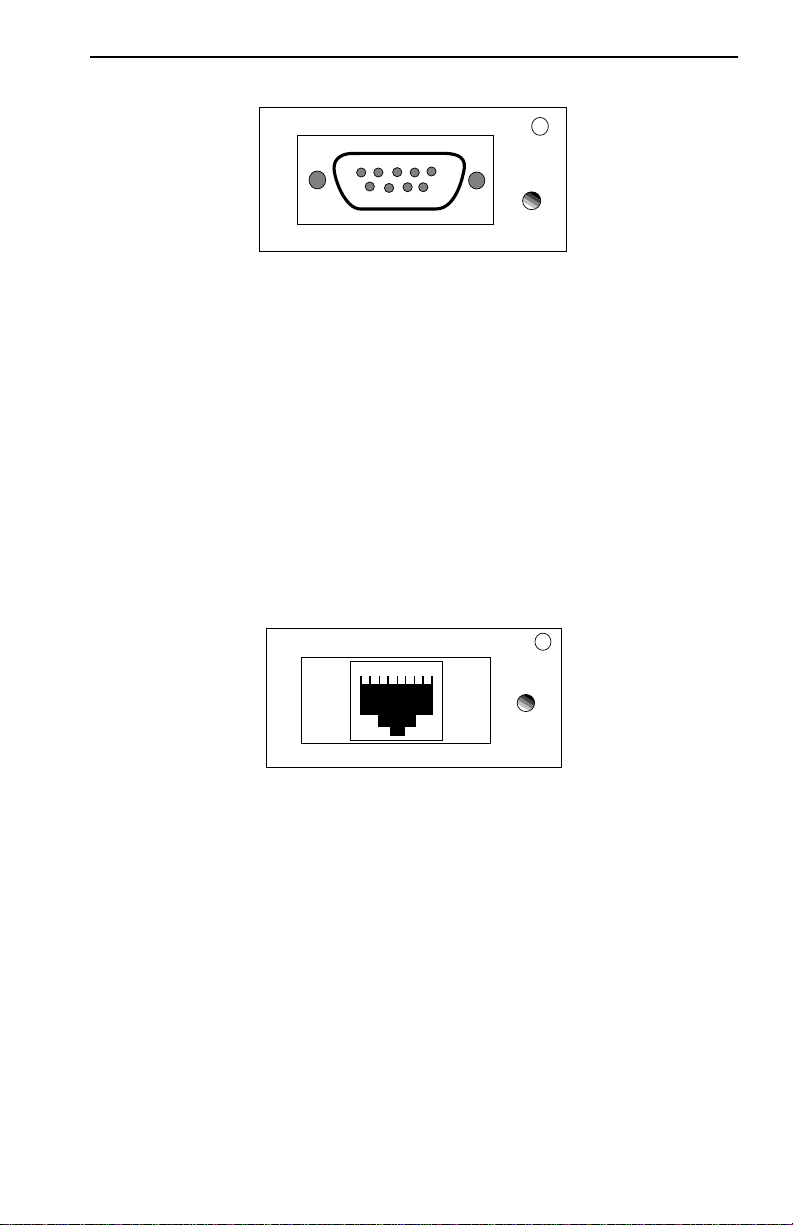
TPIM-T1
TPIM-T1 provides a female DB9 connector that supports STP cabling.
Figure 2-3 shows TPIM-T1 pinouts for Ring Out and Ring In applications.
REQUIREMENTS/SPECIFICATIONS
2-11
Figure 2-3. TPIM-T1 Pinouts
TPIM-T2
TPIM-T2 provides an RJ45 connector that supports UTP cabling.
Figure 2-4 shows pinouts for Ring Out and Ring In applications.
Figure 2-4. TPIM-T2 Pinouts
TPIM-T4
TPIM-T4 is an RJ45 connector that supports STP cabling. Figure 2-5
shows pinouts for Ring Out and Ring In applications.
RING OUT
1. Transmit +
2. Ground
3. +5V at 250 mA
4. Ground
5. Receive -
6. Transmit -
7. Ground
8. Ground
9. Receive +
TPIM-T1
LNK
5 4 3 2 1
9 8 7 6
RING IN
1. Receive +
2. Ground
3. +5V at 250 mA
4. Ground
5. Transmit -
6. Receive -
7. Ground
8. Ground
9. Transmit +
RING OUT
1. Not Used
2. Not Used
3. Receive -
4. Transmit +
5. Transmit -
6. Receive +
7. Not Used
8. Not Used
RING IN
1. Not Used
2. Not Used
3. Transmit -
4. Receive +
5. Receive -
6. Transmit +
7. Not Used
8. Not Used
TPIM-T2
LNK
1 2 3 4 5 6 7 8
Loading...