


 Loading...
SmartCell 6A000 User
Guide
35 Industrial Way Rochester, NH 03866 USA
(603) 332-9400
Part Number 04-0045-02 Rev-A
Order Number 9032539
NOTICE
Cabletron Systems reserves the right to make changes in specifications and other information contained in this document without prior notice. The reader should in all cases consult Cabletron Systems to determine whether any such changes have been made. The hardware, firmware, and software described in this manual are subject to change without notice.
IN NO EVENT SHALL CABLETRON SYSTEMS BE LIABLE FOR ANY INCIDENTAL, INDIRECT, SPECIAL, OR CONSEQUENTIAL DAMAGES WHATSOEVER (INCLUDING, BUT NOT LIMITED TO, LOST PROFITS) ARISING OUT OF OR RELATED TO THIS MANUAL OR THE INFORMATION CONTAINED IN IT, EVEN IF CABLETRON SYSTEMS HAS BEEN ADVISED OF, KNOWN, OR SHOULD HAVE KNOWN, THE POSSIBILITY OF SUCH DAMAGES.
Copyright 1998 by Cabletron Systems, Inc., P.O. Box 5005, Rochester, NH 03866-5005 All Rights Reserved
Printed in the United States of America
SmartCell 6A000 User Guide
Part Number: 04-0045-02 Rev-A
Order Number: 9032539
SmartCell, SPECTRUM, LANVIEW, MicroMMAC, and BRIM are registered trademarks and Element Manager, EPIM, EPIMA, EPIM-F1, EPIM-F2, EPIM-F3, EPIM-T, EPIM-X, FOT-F, FOT-F3, HubSTACK, SEH, SEHI, and TMS-3 are trademarks of Cabletron Systems, Inc. All other product names mentioned in this manual may be trademarks or registered trademarks of their respective companies.
ii SmartCell 6A000 User Guide

FCC CLASS A NOTICE
This device complies with Part 15 of the FCC rules. Operation is subject to the following two conditions: (1) this device may not cause harmful interference, and (2) this device must accept any interference received, including interference that may cause undesired operation.
Note This equipment has been tested and found to comply with the limits for a Class A digital device, pursuant to Part 15 of the FCC rules. These limits are designed to provide reasonable protection against harmful interference when the equipment is operated in a commercial environment. This equipment uses, generates, and can radiate radio frequency energy and, if not installed in accordance with the SmartCell 6A000 User Guide, may cause harmful interference to radio communications. Operation of this equipment in a residential area is likely to cause interference, in which case the user will be required to correct the interference at his own expense.
Note Changes or modifications made to this device, which are not expressly approved by the party responsible for compliance, could void the user’s authority to operate the equipment.
DOC CLASS A NOTICE
This digital apparatus does not exceed the Class A limits for radio noise emissions from digital apparatus set out in the Radio Interference Regulations of the Canadian Department of Communications.
Le present appareil numerique n’emet pas de bruits radioelectriques depassant les limites applicables aux appareils numeriques de la class A prescrites dans le Reglement sur le brouillage radioelectrique edicte par le ministere des Communications du Canada.
SmartCell 6A000 User Guide iii
DECLARATION OF CONFORMITY
ADDENDUM
Application of Council Directive(s): |
89/336/EEC |
|
73/23/EEC |
Manufacturer’s Name: |
Cabletron Systems, Inc. |
Manufacturer’s Address: |
35 Industrial Way |
|
P. O. Box 5005 |
|
Rochester, NH 03866 |
Product Name: |
SmartCell 6A000 |
European Representative Name: |
Mr. J. Solari |
European Representative Address: |
Cabletron Systems, Limited |
|
Nexus House, Newbury Business Park |
|
London Road, Newbury |
|
Berkshire RG13 2PZ, England |
Conformance to Directive(s)/Product Standards: |
EC Directive 89/336/EEC |
|
EC Directive 73/23/EEC |
|
EN 55022 |
|
EN 50082-1 |
|
EN 60950 |
Equipment Type/Environment: |
Networking Equipment, for use in a Commercial or Light |
|
Industrial Environment. |
We the undersigned, hereby declare, under our sole responsibility, that the equipment packaged with this notice conforms to the above directives.
Manufacturer: |
Full Name: |
Mr. Ronald Fotino |
|
Title: |
Principal Compliance Engineer |
|
Location: |
Rochester, NH. U.S.A. |
Legal Representative in Europe: |
Full Name: |
Mr. J. Solari |
|
Title: |
Managing Director - E.M.E.A. |
|
Location: |
Newbury, Berkshire, England |
iv SmartCell 6A000 User Guide
SAFETY INFORMATION
CLASS 1 LASER TRANSCEIVERS
The 6A-IOM-29-4, 6A-IOM-29-4-IR, 6A-IOM-29-4-LR, 6A-IOM-39-1 and 6A-IOM-39-1-LR connectors use Class 1 Laser transceivers. Read the following safety information before installing or operating the 6A-IOM-29-4.
The Class 1 Laser transceivers use an optical feedback loop to maintain Class 1 operation limits. This control loop eliminates the need for maintenance checks or adjustments. The output is factory set, and does not allow any user adjustment. Class 1 Laser transceivers comply with the following safety standards:
•21 CFR 1040.10 and 1040.11 U. S. Department of Health and Human Services (FDA)
•IEC Publication 825 (International Electrotechnical Commission)
•CENELEC EN 60825 (European Committee for Electrotechnical Standardization)
When operating within their performance limitations, laser transceiver output meets the Class 1 accessible emission limit of all three standards. Class 1 levels of laser radiation are not considered hazardous.
LASER RADIATION AND CONNECTORS
When the connector is in place, all laser radiation remains within the fiber. The maximum amount of radiant power exiting the fiber (under normal conditions) is -12.6dBm or 55 x 10 -6 watts.
Removing the optical connector from the transceiver allows laser radiation to emit directly from the optical port. The maximum radiance from the optical port (under worst case conditions) is 0.8 W cm-2 or 8 x 10³ W m-2 sr-1.
Do not use optical instruments to view the laser output. The use of optical instruments to view laser output increases eye hazard. When viewing the output optical port, you must remove power from the network adapter.
SmartCell 6A000 User Guide v
FIBER OPTIC PROTECTIVE CAPS
Caution READ BEFORE REMOVING FIBER OPTIC PROTECTIVE CAPS.
Cable assemblies and MMF/SMF ports are shipped with protective caps to prevent contamination. To avoid contamination, replace port caps on all fiber optic devices when not in use.
Cable assemblies and MMF/SMF ports that become contaminated may experience signal loss or difficulty inserting and removing cable assemblies from MMF/SMF ports.
Contamination can be removed from cable assemblies by
•Blowing surfaces with canned duster (Chemtronics p/n ES1270 or equivalent).
•Using a fiber port cleaning swab (Alcoa Fujikura LTS p/n ACT-01 or equivalent) saturated with optical-grade isopropyl alcohol, gently wipe the end surface of ferrules first; then wipe down the sides of both ferrules.
•Blow ferrule surfaces dry with canned duster.
Contamination can be removed from MMF/SMF ports by
•Using the extension tube supplied with canned duster, blow into the optical port, being careful not to allow the extension tube to touch the bottom of the optical port.
•Reconnect cable and check for proper mating. If problems remain, gently wipe out optical port with a DRY fiber port cleaning swab and repeat step 1.
Caution To avoid contamination, replace port caps on all fiber optic devices when not in use.
vi SmartCell 6A000 User Guide
REGULATORY COMPLIANCE SUMMARY
SAFETY
The SmartCell 6A000 meets the safety requirements of UL 1950, CSA C22.2 No. 950, EN 60950, IEC 950, and 73/23/EEC.
EMC
The SmartCell 6A000 meets the EMC requirements of FCC Part 15, EN 55022, CSA C108.8, VCCI V-3/93.01, EN 50082-1, and 89/336/EEC.
SmartCell 6A000 User Guide vii
REVISION HISTORY
Document Name: |
SmartCell 6A000 User Guide |
Document Part Number: |
04-0045-02 Rev-A |
Document Order number: |
9032539 |
Author: Bruce Jordan |
|
Editor: Carre Gibson |
|
Illustrator: Michael Fornalski |
|
Cover Designer: Michael Fornalski
Date |
Revision |
Description |
|
|
|
September 1997 |
04-0045-01 Rev-A |
Initial Release |
|
|
|
March 1998 |
04-0045-02 Rev-A |
Second Release |
|
|
|
viii SmartCell 6A000 User Guide

TABLE OF CONTENTS
1 |
Introduction. . . . . . . . . . . . . . . . . . . . . . . . . . . . . . . . . . . . . . . . . . . . . . . . . . |
1-1 |
2 |
Switch Installation and Setup . . . . . . . . . . . . . . . . . . . . . . . . . . . . . . . . . . . . |
2-1 |
2.1 |
Unpacking the Switch . . . . . . . . . . . . . . . . . . . . . . . . . . . . . . . . . . . . . . . . . . . . . . . . . . . . . . . . . . . . . |
. 2-1 |
2.1.1 |
Check Accessory Carton Contents. . . . . . . . . . . . . . . . . . . . . . . . . . . . . . . . . . . . . . . . . . . . . . . . |
. 2-1 |
2.2 |
Inspecting the Switch . . . . . . . . . . . . . . . . . . . . . . . . . . . . . . . . . . . . . . . . . . . . . . . . . . . . . . . . . . . . . |
. 2-1 |
2.2.1 |
DS3 and E3 I/O Module Configuration . . . . . . . . . . . . . . . . . . . . . . . . . . . . . . . . . . . . . . . . . . . . |
. 2-3 |
2.3 |
Installing the Switch . . . . . . . . . . . . . . . . . . . . . . . . . . . . . . . . . . . . . . . . . . . . . . . . . . . . . . . . . . . . . . |
. 2-3 |
2.4 |
Configuring the Switch . . . . . . . . . . . . . . . . . . . . . . . . . . . . . . . . . . . . . . . . . . . . . . . . . . . . . . . . . . . . |
. 2-5 |
2.5 |
Using the Console . . . . . . . . . . . . . . . . . . . . . . . . . . . . . . . . . . . . . . . . . . . . . . . . . . . . . . . . . . . . . . . . |
. 2-8 |
2.5.1 |
Console Commands . . . . . . . . . . . . . . . . . . . . . . . . . . . . . . . . . . . . . . . . . . . . . . . . . . . . . . . . . . . |
. 2-8 |
2.5.2 |
Console Time-out. . . . . . . . . . . . . . . . . . . . . . . . . . . . . . . . . . . . . . . . . . . . . . . . . . . . . . . . . . . . . |
2-10 |
2.5.3 |
Creating an Alias . . . . . . . . . . . . . . . . . . . . . . . . . . . . . . . . . . . . . . . . . . . . . . . . . . . . . . . . . . . . . |
2-10 |
2.5.4 |
Ambiguous Commands . . . . . . . . . . . . . . . . . . . . . . . . . . . . . . . . . . . . . . . . . . . . . . . . . . . . . . . . |
2-11 |
2.5.5 |
Console Help . . . . . . . . . . . . . . . . . . . . . . . . . . . . . . . . . . . . . . . . . . . . . . . . . . . . . . . . . . . . . . . . |
2-11 |
2.6 |
SmartSwitch ATM Administrator . . . . . . . . . . . . . . . . . . . . . . . . . . . . . . . . . . . . . . . . . . . . . . . . . . . . |
2-12 |
2.6.1 |
Installation Steps . . . . . . . . . . . . . . . . . . . . . . . . . . . . . . . . . . . . . . . . . . . . . . . . . . . . . . . . . . . . . |
2-13 |
2.6.2 |
Starting SmartSwitch ATM Administrator the First Time . . . . . . . . . . . . . . . . . . . . . . . . . . . . . |
2-14 |
2.6.3 |
Accessing Online Help. . . . . . . . . . . . . . . . . . . . . . . . . . . . . . . . . . . . . . . . . . . . . . . . . . . . . . . . . |
2-15 |
3 |
IP Over ATM and LANE . . . . . . . . . . . . . . . . . . . . . . . . . . . . . . . . . . . . . . . . |
3-1 |
3.1 |
Creating an IP over ATM VLAN . . . . . . . . . . . . . . . . . . . . . . . . . . . . . . . . . . . . . . . . . . . . . . . . . . . . |
. 3-1 |
3.1.1 |
ATM Addressing for IP over ATM . . . . . . . . . . . . . . . . . . . . . . . . . . . . . . . . . . . . . . . . . . . . . . . |
. 3-3 |
3.2 |
Creating an Emulated LAN. . . . . . . . . . . . . . . . . . . . . . . . . . . . . . . . . . . . . . . . . . . . . . . . . . . . . . . . . |
. 3-3 |
3.2.1 |
ATM Addressing for LAN Emulation . . . . . . . . . . . . . . . . . . . . . . . . . . . . . . . . . . . . . . . . . . . . . |
. 3-6 |
3.2.2 |
ELANs Across Multiple Switches . . . . . . . . . . . . . . . . . . . . . . . . . . . . . . . . . . . . . . . . . . . . . . . . |
. 3-6 |
3.2.3 |
Switch Clients . . . . . . . . . . . . . . . . . . . . . . . . . . . . . . . . . . . . . . . . . . . . . . . . . . . . . . . . . . . . . . . |
. 3-6 |
4 |
Switch Administration . . . . . . . . . . . . . . . . . . . . . . . . . . . . . . . . . . . . . . . . . . |
4-1 |
4.1 |
Backing Up and Restoring Switch Configuration. . . . . . . . . . . . . . . . . . . . . . . . . . . . . . . . . . . . . . . . |
. 4-1 |
4.2 |
ATM Routing . . . . . . . . . . . . . . . . . . . . . . . . . . . . . . . . . . . . . . . . . . . . . . . . . . . . . . . . . . . . . . . . . . . |
. 4-2 |
4.2.1 |
Creating an IISP Route . . . . . . . . . . . . . . . . . . . . . . . . . . . . . . . . . . . . . . . . . . . . . . . . . . . . . . . . |
. 4-2 |
4.2.2 |
UNI Routes . . . . . . . . . . . . . . . . . . . . . . . . . . . . . . . . . . . . . . . . . . . . . . . . . . . . . . . . . . . . . . . . . |
. 4-5 |
4.2.3 |
Route Metrics . . . . . . . . . . . . . . . . . . . . . . . . . . . . . . . . . . . . . . . . . . . . . . . . . . . . . . . . . . . . . . . . |
. 4-6 |
4.3 |
IP Routing . . . . . . . . . . . . . . . . . . . . . . . . . . . . . . . . . . . . . . . . . . . . . . . . . . . . . . . . . . . . . . . . . . . . . . |
. 4-7 |
4.4 |
Events and Alarms . . . . . . . . . . . . . . . . . . . . . . . . . . . . . . . . . . . . . . . . . . . . . . . . . . . . . . . . . . . . . . . |
. 4-9 |
4.4.1 |
Event Categories . . . . . . . . . . . . . . . . . . . . . . . . . . . . . . . . . . . . . . . . . . . . . . . . . . . . . . . . . . . . . |
. 4-9 |
4.4.2 |
Viewing Events and Alarms . . . . . . . . . . . . . . . . . . . . . . . . . . . . . . . . . . . . . . . . . . . . . . . . . . . . |
4-10 |
4.4.3 |
Deleting Events and Alarms . . . . . . . . . . . . . . . . . . . . . . . . . . . . . . . . . . . . . . . . . . . . . . . . . . . . |
4-11 |
SmartCell 6A000 User Guide ix
|
|
TABLE OF CONTENTS |
4.5 |
PVC Connections . . . . . . . . . . . . . . . . . . . . . . . . . . . . . . . . . . . . . . . . . . . . . . . . . . |
. . . . . . . . . . . . . . 4-11 |
4.5.1 |
Point-to-Point PVCs . . . . . . . . . . . . . . . . . . . . . . . . . . . . . . . . . . . . . . . . . . . . . |
. . . . . . . . . . . . . . 4-12 |
4.5.2 |
Point-to-Multipoint PVCs . . . . . . . . . . . . . . . . . . . . . . . . . . . . . . . . . . . . . . . . |
. . . . . . . . . . . . . . 4-12 |
4.5.3 |
Connecting to Local Switch Client Through a PVC . . . . . . . . . . . . . . . . . . . . . |
. . . . . . . . . . . . . 4-14 |
4.5.4 |
Non-zero VPIs . . . . . . . . . . . . . . . . . . . . . . . . . . . . . . . . . . . . . . . . . . . . . . . . . . |
. . . . . . . . . . . . . 4-14 |
4.6 |
Traffic Management . . . . . . . . . . . . . . . . . . . . . . . . . . . . . . . . . . . . . . . . . . . . . . . . . |
. . . . . . . . . . . . . 4-17 |
4.6.1 |
Traffic Descriptors . . . . . . . . . . . . . . . . . . . . . . . . . . . . . . . . . . . . . . . . . . . . . . . |
. . . . . . . . . . . . . 4-17 |
4.6.2 |
Call Admission Control Policy. . . . . . . . . . . . . . . . . . . . . . . . . . . . . . . . . . . . . . |
. . . . . . . . . . . . . 4-19 |
4.6.3 |
EFCI, EPD, and RM Thresholds . . . . . . . . . . . . . . . . . . . . . . . . . . . . . . . . . . . . |
. . . . . . . . . . . . . 4-22 |
4.7 |
Upgrading and Changing Software . . . . . . . . . . . . . . . . . . . . . . . . . . . . . . . . . . . . . . |
. . . . . . . . . . . . . 4-23 |
4.7.1 |
Accessing the Boot Load Prompt . . . . . . . . . . . . . . . . . . . . . . . . . . . . . . . . . . . . |
. . . . . . . . . . . . . 4-23 |
4.7.2 |
Boot Load Commands . . . . . . . . . . . . . . . . . . . . . . . . . . . . . . . . . . . . . . . . . . . . |
. . . . . . . . . . . . . 4-24 |
4.7.3 |
Upgrading Boot Load Software . . . . . . . . . . . . . . . . . . . . . . . . . . . . . . . . . . . . . |
. . . . . . . . . . . . . 4-25 |
4.7.4 |
Upgrading POST Diagnostic Software . . . . . . . . . . . . . . . . . . . . . . . . . . . . . . . |
. . . . . . . . . . . . . 4-27 |
4.7.5 |
Upgrading Switch Operating Software . . . . . . . . . . . . . . . . . . . . . . . . . . . . . . . |
. . . . . . . . . . . . . 4-28 |
4.7.6 |
Using the Update Firmware Command . . . . . . . . . . . . . . . . . . . . . . . . . . . . . . . |
. . . . . . . . . . . . . 4-29 |
4.8 |
Saving Core Dumps. . . . . . . . . . . . . . . . . . . . . . . . . . . . . . . . . . . . . . . . . . . . . . . . . . |
. . . . . . . . . . . . . 4-30 |
5 |
Troubleshooting . . . . . . . . . . . . . . . . . . . . . . . . . . . . . . . . . . . . |
. . . . . . . . . .5-1 |
5.1 |
Troubleshooting IP over ATM . . . . . . . . . . . . . . . . . . . . . . . . . . . . . . . . . . . . . . . . . |
. . . . . . . . . . . . . . 5-1 |
5.2 |
Troubleshooting LAN Emulation . . . . . . . . . . . . . . . . . . . . . . . . . . . . . . . . . . . . . . . |
. . . . . . . . . . . . . . 5-2 |
5.3 |
Troubleshooting PNNI Links . . . . . . . . . . . . . . . . . . . . . . . . . . . . . . . . . . . . . . . . . . |
. . . . . . . . . . . . . . 5-3 |
5.4 |
Troubleshooting Congestion . . . . . . . . . . . . . . . . . . . . . . . . . . . . . . . . . . . . . . . . . . . |
. . . . . . . . . . . . . . 5-3 |
5.4.1 |
Diagnosing Congestion . . . . . . . . . . . . . . . . . . . . . . . . . . . . . . . . . . . . . . . . . . . |
. . . . . . . . . . . . . . 5-4 |
5.4.2 |
Global Congestion . . . . . . . . . . . . . . . . . . . . . . . . . . . . . . . . . . . . . . . . . . . . . . . |
. . . . . . . . . . . . . . 5-4 |
5.4.3 |
Port Congestion . . . . . . . . . . . . . . . . . . . . . . . . . . . . . . . . . . . . . . . . . . . . . . . . . |
. . . . . . . . . . . . . . 5-5 |
A |
Specifications . . . . . . . . . . . . . . . . . . . . . . . . . . . . . . . . . . . . . . |
. . . . . . . . . A-1 |
A.1 |
Front Panel. . . . . . . . . . . . . . . . . . . . . . . . . . . . . . . . . . . . . . . . . . . . . . . . . . . . . . . . . |
. . . . . . . . . . . . . A-1 |
A.2 |
Technical Specifications . . . . . . . . . . . . . . . . . . . . . . . . . . . . . . . . . . . . . . . . . . . . . . |
. . . . . . . . . . . . . A-2 |
B |
Agent Support . . . . . . . . . . . . . . . . . . . . . . . . . . . . . . . . . . . . . . |
. . . . . . . . . B-1 |
B.1 |
MIB, SMI, MIB Files and Internet MIB Hierarchy. . . . . . . . . . . . . . . . . . . . . . . . . . |
. . . . . . . . . . . . . B-1 |
B.1.1 |
ZeitNet Cabletron Proprietary MIBs . . . . . . . . . . . . . . . . . . . . . . . . . . . . . . . . . |
. . . . . . . . . . . . . B-2 |
B.1.2 |
Relation Between Object Identifier and the Represented Value . . . . . . . . . . . . |
. . . . . . . . . . . . . B-3 |
B.1.3 |
Supported protocols . . . . . . . . . . . . . . . . . . . . . . . . . . . . . . . . . . . . . . . . . . . . . . |
. . . . . . . . . . . . . B-4 |
B.1.4 |
Supported SMI Formats . . . . . . . . . . . . . . . . . . . . . . . . . . . . . . . . . . . . . . . . . . . |
. . . . . . . . . . . . . B-4 |
B.1.5 |
Zeitnet Cabletron Proprietary MIB Groups . . . . . . . . . . . . . . . . . . . . . . . . . . . . |
. . . . . . . . . . . . . B-4 |
B.1.6 |
SmartCell 6A000 MIB Support . . . . . . . . . . . . . . . . . . . . . . . . . . . . . . . . . . . . . |
. . . . . . . . . . . . . B-5 |
B.1.7 |
MIB Exceptions . . . . . . . . . . . . . . . . . . . . . . . . . . . . . . . . . . . . . . . . . . . . . . . . . |
. . . . . . . . . . . . . B-6 |
B.2 |
Managing the SmartCell 6A000 . . . . . . . . . . . . . . . . . . . . . . . . . . . . . . . . . . . . . . . . |
. . . . . . . . . . . . . B-7 |
B.2.1 |
Console Commands that Affect the Agent . . . . . . . . . . . . . . . . . . . . . . . . . . . . . |
. . . . . . . . . . . . . B-7 |
C |
Technical Support . . . . . . . . . . . . . . . . . . . . . . . . . . . . . . . . . . . |
. . . . . . . . . C-1 |
C.1 |
Telephone Assistance . . . . . . . . . . . . . . . . . . . . . . . . . . . . . . . . . . . . . . . . . . . . . . . . |
. . . . . . . . . . . . . C-1 |
C.2 |
FAX Service . . . . . . . . . . . . . . . . . . . . . . . . . . . . . . . . . . . . . . . . . . . . . . . . . . . . . . . |
. . . . . . . . . . . . . C-1 |
x SmartCell 6A000 User Guide
TABLE OF CONTENTS
C.3 |
Electronic Services . . . . . . . . . . . . . . . . . . . . . . . . . . . . . . . . . . . . . . . . . . . . . . . . . . . . . . . . . . . . . . . |
. C-1 |
C.4 |
Placing A Support Call . . . . . . . . . . . . . . . . . . . . . . . . . . . . . . . . . . . . . . . . . . . . . . . . . . . . . . . . . . . . . |
C-1 |
C.5 |
Hardware Warranty . . . . . . . . . . . . . . . . . . . . . . . . . . . . . . . . . . . . . . . . . . . . . . . . . . . . . . . . . . . . . . . . |
C-2 |
C.6 |
Software Warranty . . . . . . . . . . . . . . . . . . . . . . . . . . . . . . . . . . . . . . . . . . . . . . . . . . . . . . . . . . . . . . . . |
C-2 |
C.7 |
Repair Services . . . . . . . . . . . . . . . . . . . . . . . . . . . . . . . . . . . . . . . . . . . . . . . . . . . . . . . . . . . . . . . . . . . |
C-2 |
D |
Acronyms . . . . . . . . . . . . . . . . . . . . . . . . . . . . . . . . . . . . . . . . . . . . . . . . . . . |
D-1 |
|
Index. . . . . . . . . . . . . . . . . . . . . . . . . . . . . . . . . . . . . . . . . . . . . . . . . . . . . . . . |
I-1 |
SmartCell 6A000 User Guide xi
TABLE OF CONTENTS
xii SmartCell 6A000 User Guide

LIST OF FIGURES
Figure 2-1 6A000-04 and 6A000-02 front panels. . . . . . . . . . . . . . . . . . . . . . . . . . . . . . . . . . . . . . . . . . . . . . . . . . 2-2 Figure 2-2 Installing the SmartCell 6A000. . . . . . . . . . . . . . . . . . . . . . . . . . . . . . . . . . . . . . . . . . . . . . . . . . . . . . . 2-5 Figure 2-3 6A000 console and network connections . . . . . . . . . . . . . . . . . . . . . . . . . . . . . . . . . . . . . . . . . . . . . . . 2-7 Figure 2-4 SmartSwitch ATM Administrator . . . . . . . . . . . . . . . . . . . . . . . . . . . . . . . . . . . . . . . . . . . . . . . . . . . . 2-13 Figure 4-1 IISP route across PNNI domain . . . . . . . . . . . . . . . . . . . . . . . . . . . . . . . . . . . . . . . . . . . . . . . . . . . . . . 4-4 Figure 4-2 Routes needed for a second IISP switch . . . . . . . . . . . . . . . . . . . . . . . . . . . . . . . . . . . . . . . . . . . . . . . . 4-4 Figure 4-3 IP routing through SW1 for connectivity to the Ethernet network . . . . . . . . . . . . . . . . . . . . . . . . . . . . 4-9 Figure 4-4 Memory locations affected by the boot load commands. . . . . . . . . . . . . . . . . . . . . . . . . . . . . . . . . . . 4-25 Figure A-1 Front panel. . . . . . . . . . . . . . . . . . . . . . . . . . . . . . . . . . . . . . . . . . . . . . . . . . . . . . . . . . . . . . . . . . . . . . .A-2 Figure B-1 Internet MIB hierarchy . . . . . . . . . . . . . . . . . . . . . . . . . . . . . . . . . . . . . . . . . . . . . . . . . . . . . . . . . . . . . B-2 Figure B-2 ZeitNet Private MIBs . . . . . . . . . . . . . . . . . . . . . . . . . . . . . . . . . . . . . . . . . . . . . . . . . . . . . . . . . . . . . . B-3 Figure B-3 ZeitNet Cabletron 6A000 MIB object identifier example . . . . . . . . . . . . . . . . . . . . . . . . . . . . . . . . . . B-4
SmartCell 6A000 User Guide xiii
List of Figures
xiv SmartCell 6A000 User Guide

LIST OF TABLES
Table 2-1 |
I/O module ID numbers . . . . . . . . . . . . . . . . . . . . . . . . . . . . . . . . . . . . . . . . . . . . . . . . . . . . . . . . . . . |
. 2-2 |
Table 2-2 |
DS3 and E3 Module settings . . . . . . . . . . . . . . . . . . . . . . . . . . . . . . . . . . . . . . . . . . . . . . . . . . . . . . . . . |
2-3 |
Table 2-3 |
SmartSwitch 6000 contents . . . . . . . . . . . . . . . . . . . . . . . . . . . . . . . . . . . . . . . . . . . . . . . . . . . . . . . . . . |
2-3 |
Table 2-4 |
Default accounts and passwords . . . . . . . . . . . . . . . . . . . . . . . . . . . . . . . . . . . . . . . . . . . . . . . . . . . . . |
2-14 |
Table 4-1 |
Values for VPI and VCI . . . . . . . . . . . . . . . . . . . . . . . . . . . . . . . . . . . . . . . . . . . . . . . . . . . . . . . . . . . |
4-15 |
Table 4-2 |
Traffic descriptor type number explanation . . . . . . . . . . . . . . . . . . . . . . . . . . . . . . . . . . . . . . . . . . . . |
4-18 |
Table 4-3 |
Settings for QoS queues . . . . . . . . . . . . . . . . . . . . . . . . . . . . . . . . . . . . . . . . . . . . . . . . . . . . . . . . . . . |
4-22 |
Table 4-4 |
Boot load commands . . . . . . . . . . . . . . . . . . . . . . . . . . . . . . . . . . . . . . . . . . . . . . . . . . . . . . . . . . . . . |
4-24 |
Table A-1 Front panel LEDs . . . . . . . . . . . . . . . . . . . . . . . . . . . . . . . . . . . . . . . . . . . . . . . . . . . . . . . . . . . . . . . . . |
A-1 |
|
Table A-2 |
Hardware Specifications . . . . . . . . . . . . . . . . . . . . . . . . . . . . . . . . . . . . . . . . . . . . . . . . . . . . . . . . . . . |
A-2 |
Table A-3 |
Physical Specifications . . . . . . . . . . . . . . . . . . . . . . . . . . . . . . . . . . . . . . . . . . . . . . . . . . . . . . . . . . . . . |
A-3 |
Table A-4 ATM Port Specifications . . . . . . . . . . . . . . . . . . . . . . . . . . . . . . . . . . . . . . . . . . . . . . . . . . . . . . . . . . . |
A-3 |
|
Table A-5 Protocols Standards and Specifications. . . . . . . . . . . . . . . . . . . . . . . . . . . . . . . . . . . . . . . . . . . . . . . . . |
A-4 |
|
Table A-6 Management Standards and Specifications. . . . . . . . . . . . . . . . . . . . . . . . . . . . . . . . . . . . . . . . . . . . . . |
A-5 |
|
Table A-7 RJ-45 to DB-9 Adapter (PC Serial Port Adapter) . . . . . . . . . . . . . . . . . . . . . . . . . . . . . . . . . . . . . . . . . |
A-5 |
|
Table B-1 |
Zeitnet proprietary MIB groupings . . . . . . . . . . . . . . . . . . . . . . . . . . . . . . . . . . . . . . . . . . . . . . . . . . . |
B-4 |
SmartCell 6A000 User Guide xv
List of Tables
xvi SmartCell 6A000 User Guide
1 INTRODUCTION
Welcome to the SmartCell 6A000 User Guide. The SmartCell 6A000 ATM switch is a module that fits into the SmartSwitch 6000 chassis. You can install as many as five SmartCell 6A000 switches into a SmartSwitch 6000 chassis (using the 6C305-3 power supply). The module is hot swappable, meaning that you can install and remove it without turning off or disconnecting the chassis. This manual will help you quickly and easily install and configure your SmartCell 6A000 switch.
By performing the steps described in the first two chapters of this manual, your switch will be physically installed, accessible on your Ethernet network, and running either an IP over ATM VLAN or an emulated Ethernet or Token Ring LAN.
Subsequent chapters provide information about switch use, maintenance, and problem solving. These topics include
•Managing the switch: backing up configurations, adding routes, creating PVC connections, upgrading software, dealing with bandwidth, and controlling congestion
•Working with the switch’s hardware components
•Troubleshooting
Note For detailed descriptions of SmartCell 6A000 console commands and their use, see the SmartCell 6A000/ZX-250 Reference Manual.
SmartCell 6A000 User Guide 1-1
Introduction
1-2 SmartCell 6A000 User Guide

2 SWITCH INSTALLATION AND SETUP
After you read this chapter, you will be able to perform the following tasks:
UInstall the SmartCell 6A000 switch module into the SmartSwitch 6000 chassis
UComplete the initial configuration
UUse the console interface
UInstall the SmartSwitch ATM Administrator graphical management software
2.1UNPACKING THE SWITCH
Remove the accessory carton from the shipping box. Carefully remove the switch from its packing material.
2.1.1Check Accessory Carton Contents
Open the accessory carton and check that it contains the following items:
—7-foot UTP cable terminated on both ends with RJ-45 connectors
—RJ-45 to 9-pin female adapter (labeled PC)
—Console cabling instruction sheet
—Diskettes containing switch software, MIB files, SmartSwitch ATM Administrator software, and release notes
—SmartCell 6A000 Release Notes
—SmartCell 6A000 User Guide
—SmartCell 6A000/ZX-250 Reference Manual
If any of these items is missing, contact Cabletron customer support immediately.
2.2INSPECTING THE SWITCH
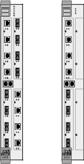
Depending on the configuration ordered, your switch looks similar to one of the units in the drawing in Figure 2-1. The 6A000-04, shown on the left, has four I/O modules. The 6A000-02, shown on the right, has two I/O modules; the empty I/O module positions are covered by metal blanks.
SmartCell 6A000 User Guide 2-1
Inspecting the Switch |
Switch Installation and Setup |
ATM |
|
|
ATM |
||||
|
|
S |
FAIL |
|
|
|
|
|
|
Y |
STATUS |
|
|
|
|
|
|
S |
POWER |
|
|
|
|
|
|
T |
|
|
|
||
|
|
RX ENET |
|
|
|
||
|
|
E |
|
|
|
||
|
|
M |
TX ENET |
|
|
|
|
|
|
1 |
1 |
|
|
|
|
|
DATA |
SYNC NO |
DATA |
SYNC NO |
|
DATA |
SYNC NO |
|
|
2 |
2 |
|
|
|
|
A |
-IOM-6A |
C |
-IOM-6A |
|
A |
-IOM-6A |
|
|
4-22 |
|
4-21 |
|
|
4-22 |
|
|
|
3 |
3 |
|
|
|
|
|
|
4 |
4 |
|
|
|
|
|
|
|
E |
|
|
|
|
|
|
|
T |
|
|
|
|
C |
|
|
H |
|
C |
|
|
|
|
E |
|
|
|
||
O |
|
|
|
O |
|
|
|
|
|
R |
|
|
|
||
M |
|
|
|
M |
|
|
|
|
|
N |
|
|
|
||
|
|
|
|
|
|
|
|
|
|
|
E |
|
|
|
|
|
|
|
T |
|
|
|
|
|
1 |
|
|
1 |
|
1 |
|
|
DATA |
SYNC NO |
DATA |
SYNC NO |
|
DATA |
SYNC NO |
|
2 |
|
|
2 |
|
2 |
|
B |
-IOM-6A |
D |
-IOM-6A |
|
B |
-IOM-6A |
|
|
4-21 |
|
4-22 |
|
|
4-21 |
|
|
3 |
|
|
3 |
|
3 |
|
|
4 |
|
|
4 |
|
4 |
|
S  FAIL
FAIL
Y  STATUS
S  POWER T
E  RX ENET M
  TX ENET
1
2
C
3
4
E
T
H
E
R
N
E
T
D
Figure 2-1 6A000-04 and 6A000-02 front panels
Inspect the switch and make certain that its configuration corresponds to what was ordered. Also, make certain that the input/output (I/O) modules are of the correct type and number (See Table 2-1).
Table 2-1 I/O module ID numbers
Face Plate Number |
Physical Specification |
|
|
|
|
6A-IOM-21-4 |
155 Mbps OC-3/STM-1, MMF/SC (4 port) |
|
|
|
|
6A-IOM-22-4 |
155 |
Mbps STS-3c/STM-1, UTP-5/RJ-45 (4port) |
|
|
|
6A-IOM-29-4 |
155 |
Mbps OC-3/STM-1, SMF-IR/SC (1port) MMF/SC (3 port) |
|
|
|
6A-IOM-29-4-IR |
155 |
Mbps OC-3/STM-1, SMF-IR/SC (4 port) |
|
|
|
2-2 SmartCell 6A000 User Guide
Switch Installation and Setup Installing the Switch
Table 2-1 I/O module ID numbers (Continued)
Face Plate Number |
Physical Specification |
|
|
|
|
6A-IOM-29-4-LR |
155 |
Mbps OC-3/STS-1, SMF-LR/SC (4 port) |
|
|
|
6A-IOM-31-1 |
622 Mbps OC-12/STM-4, MMF/SC (1 port) |
|
|
|
|
6A-IOM-39-1 |
622 |
Mbps OC-12/STM-4, SMF-IR/SC (1 port) |
|
|
|
6A-IOM-39-1-LR |
622 |
Mbps OC-12/STM-4, SMF-LR/SC (1 port) |
|
|
|
6A-IOM-67-4 |
45 Mbps DS-3, Coax/BNC (4 port) |
|
|
|
|
6A-IOM-77-4 |
34 Mbps E-3, Coax/BNC (4 port) |
|
|
|
|
If the hardware configuration is incorrect, contact Cabletron customer support immediately.
2.2.1DS3 and E3 I/O Module Configuration
Table 2-2 shows the pre-configured values for both the DS3 (6A-IOM-67-4) and E3 (6A-IOM-77-4) I/O modules. These values cannot be changed. Accordingly, configure the connecting device’s interface to use these values.
Table 2-2 DS3 and E3 Module settings
Protocol |
Mode |
Framing |
Empty Cell |
Timing |
Scrambling |
Length |
|
|
|
|
|
|
|
DS3 |
plcp |
cbit |
unassigned |
internal |
off |
greater than 225 ft. |
|
|
|
|
|
|
|
E3 |
plcp |
G.751 |
unassigned |
internal |
off |
N/A |
|
|
|
|
|
|
|
2.3INSTALLING THE SWITCH
The SmartCell 6A000 is hot swappable, meaning that you can install and remove it without turning off or unplugging the SmartSwitch 6000 chassis. You can install as many as five switch modules in each chassis (using the 6C205-3 power supply). In this configuration, the SmartCell 6A000 modules provide up to 75 user ports. Modules should be connected with inter-module trunks if traffic must cross between modules. Table 2-3 shows the maximum number of LAN and ATM switch modules that can be installed in a SmartSwitch 6000 chassis.
Table 2-3 SmartSwitch 6000 contents
Number of 6Exxx or 6Hxxx modules installed |
0 |
1 |
2 |
3 |
4 |
5 |
|
|
|
|
|
|
|
Number of 6A000 modules that can be added |
5 |
4 |
3 |
2 |
1 |
0 |
|
|
|
|
|
|
|
SmartCell 6A000 User Guide 2-3

Installing the Switch |
Switch Installation and Setup |
2p›F A single 6C205-1 power supply (the older version of the 6C205-3) can support only two SmartCell 6A000s within a SmartSwitch 6000 chassis. Three SmartCell 6A000s can reside within a SmartSwitch 6000 chassis that contains two 6C205-1 power supplies.
Follow the instructions below to install the switch module into the chassis. Refer to Figure 2-2. s• Remove the metal blank that covers one of the empty slots in the chassis.
¢• Open the ejectors at the top and bottom of the switch module.
•• With the LEDs at the top, align the top and bottom of the SmartCell 6A000 with the tracks in the slot.
T• Slide the switch into the chassis. The switch module obscures the view of the tracks at the bottom of the chassis, so be sure to look at that area as you begin to slide the switch into the chassis.
Q• Close the ejectors. The installation is complete.
2-4 SmartCell 6A000 User Guide

Switch Installation and Setup |
Configuring the Switch |
Rotate ejector to lock in place
Circuit Card
Metal Backpanel |
Card Guides
Figure 2-2 Installing the SmartCell 6A000
2.4CONFIGURING THE SWITCH
Initial configuration of your SmartCell 6A000 switch consists of setting the name, Ethernet IP address, and subnet mask. Once these tasks are complete, the switch can be reached through your Ethernet network for additional configuration and administration.
Perform the following steps to configure initial switch parameters:
s• Determine whether you will use a dumb terminal, workstation, or PC running terminal emulation software to perform initial switch configuration.
SmartCell 6A000 User Guide 2-5

Configuring the Switch |
Switch Installation and Setup |
¢• Configure dumb terminals or PCs running emulation software with the following communication parameters:
UBaud rate = 9600
UData bits = 8
UStop bits = 1
UFlow control = none
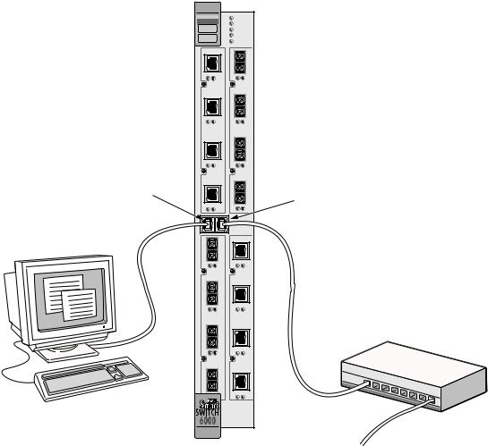
•• Plug one end of the supplied RJ-45 UTP cable into the 9-pin RJ-45 adapter (see Figure 2-3)
2p›F For information about adapter wiring configurations, see Appendix A, "Specifications."
T• Plug the other end of the UTP cable into the SmartCell 6A000 female RJ-45 jack labeled Terminal, located on the front panel (see Figure 2-3).
Q• Connect the switch to your network by plugging a UTP cable into the SmartCell 6A000 female RJ-45 jack labeled Ethernet, located near the center of the switch's front panel (see Figure 2-3).
2-6 SmartCell 6A000 User Guide
Switch Installation and Setup |
Configuring the Switch |
ATM |
|
|
|
|
S |
FAIL |
|
|
Y |
STATUS |
|
|
S |
POWER |
|
|
T |
||
|
RX ENET |
||
|
E |
||
|
M |
TX ENET |
|
|
1 |
1 |
|
DATA |
SYNC NO |
DATA |
SYNC NO |
|
2 |
2 |
|
4-22-IOM-6A |
|
4-21-IOM-6A |
|
|
3 |
3 |
|
Terminal |
4 |
4 |
Ethernet |
RJ-45 |
|
|
RJ-45 |
Port |
|
|
Port |
1 |
|
|
1 |
DATA |
SYNC NO |
DATA |
SYNC NO |
2 |
|
|
2 |
4-21-IOM-6A |
|
4-22-IOM-6A |
|
3 |
|
|
3 |
4 |
|
|
4 |
Terminal |
|
|
Ethernet |
|
|
Hub |
|
|
|
|
|
Figure 2-3 6A000 console and network connections
–• Start the dumb terminal or PC and its terminal emulation software.
••As soon as power is applied to the SmartCell 6A000, the module emits a series of diagnostic messages. If you inserted the module into a chassis that was turned off, turn it on now to see the diagnostics. If you inserted the module into a chassis that was turned on, press the Reset switch to see the diagnostics.
G• After the diagnostics are finished, the switch prompts for a password. Enter the default password, "admin."
n• Next, the switch prompts for the information necessary to make the switch accessible through your Ethernet network
USwitch name
UIP address
USubnet mask
SmartCell 6A000 User Guide 2-7

Using the Console |
Switch Installation and Setup |
s¥ After you enter these parameters and reboot the switch, log off the local console connection. Perform additional configuration steps over your network using a telnet connection.
2p›F Only one console connection is allowed at any time. To reach the SmartCell 6A000 through telnet, you must exit the local terminal connection by entering the exit command.
The following is an example of the initial configuration session:
SmartCell ZX Version 2.1 (c) Cabletron Inc. password:: admin
The current user is Administrator
Could not find setup file
Running Setup Automatically
SwitchName() : My_6A000
IPAddress(0.0.0.0) : 210.160.77.254
IPNetMask(255.0.0.0) : 255.255.255.0
Confirm(y/n)?:y
Changing IP Address on System. Telnet session (if any) will be lost.
SmartCell ZX #
Before continuing to chapter 3, “IP over ATM and LANE,” read the following sections for information about
UUsing the SmartCell 6A000 console
UInstalling and getting started with the Windows-based SmartSwitch ATM Administrator application
2.5USING THE CONSOLE
Use the SmartCell 6A000 console interface to configure and manage your switch. The following is a description of the console interface and its operation.
2.5.1Console Commands
2p›F For detailed descriptions of console commands, see the SmartCell 6A000/ZX-250 Reference Manual.
All console commands use the syntax:
operator switch-attribute [<parameter 1> <parameter 2>... <parameter n>]
Where the operator is one of the following:
show ( display): Show the current values used by a switch-attribute. add ( create): Add a new instance of a switch-attribute.
delete ( remove): Delete an instance of a switch-attribute.
modify ( set): Change the values that currently define a switch-attribute.
2-8 SmartCell 6A000 User Guide
Switch Installation and Setup |
Using the Console |
start: Start a process on the switch; for example, start the LAN Emulation Configuration Server.
restart: Restart a process on the switch; for example, restart a client.
flush: Remove assigned values; for example, flush a route table.
alias: Create easier names for often-used commands and their parameters.
Entering parameters at the command line is optional. If a command requires parameter values, it prompts you for them. For instance, in the example below, show is the operator, portconfig is the switch-attribute, and a1 is the parameter indicating that you want to show configuration information about port A1.
SmartCell ZX # show portconfig a1
==================================================
Port: A1
--------------------------------------------------
Parameter |
Configured |
Current |
|
-------------------------------------------------- |
|||
Sig |
Type |
autoConfig |
pnni10 |
Sig |
Role |
other |
symmetric |
Interface Type |
private |
private |
|
Max |
vpi bits |
0 |
0 |
Max |
vci bits |
12 |
12 |
Max |
SVC vpci |
0 |
0 |
Min |
SVC vci |
32 |
32 |
Max |
Vccs |
4096 |
4096 |
-------------------------------------------------- |
|||
Other parameters |
|
|
|
-------------------------------------------------- |
|||
Port Admin Status |
UP |
|
|
Ilmi |
Admin Status |
Enabled AddressRegistration Connectivity |
|
Oper State |
UP |
|
|
Trans Type |
STS-3c |
|
|
Media Type |
MMF (S) |
|
|
Bandwidth |
155 MB |
|
|
SmartCell ZX # |
|
|
|
If you don’t specify parameters with the command, the console prompts you for an input value and provides a default value displayed in parenthesis. For example, if you enter show portconfig without specifying a port (as a parameter), the following appears. Here, the default of “ all” ports is presented. You can either accept the default by pressing Enter, or you can enter a specific port number. Taking the default displays the following:
SmartCell ZX # show portconfig |
|
|
|
|
||
PortNumber(ALL) |
|
|
: |
|
|
|
Port |
Intf |
Sig |
Trans |
Media |
Speed |
Oper |
ID |
Type |
Type |
Type |
Type |
(MB/s) |
State |
==============================================================================
A1 |
private |
pnni10 |
STS-3c |
MMF (S) |
155 |
MB |
UP |
A2 |
private |
autoConfig |
STS-3c |
MMF (S) |
155 |
MB |
DOWN |
A3 |
private |
autoConfig |
STS-3c |
MMF (S) |
155 |
MB |
DOWN |
A4 |
private |
autoConfig |
STS-3c |
MMF (S) |
155 |
MB |
DOWN |
B1 |
private |
autoConfig |
STS-3c |
MMF (S) |
155 |
MB |
DOWN |
B2 |
private |
autoConfig |
STS-3c |
MMF (S) |
155 |
MB |
DOWN |
B3 |
private |
autoConfig |
STS-3c |
MMF (S) |
155 |
MB |
DOWN |
B4(CPU) |
private |
uni31 |
STS-3c |
MMF (S) |
155 |
MB |
UP |
C1 |
private |
autoConfig |
STS-3c |
SMF (I) |
155 |
MB |
DOWN |
C2 |
private |
autoConfig |
STS-3c |
MMF (S) |
155 |
MB |
DOWN |
C3 |
private |
autoConfig |
STS-3c |
MMF (S) |
155 |
MB |
DOWN |
C4 |
private |
autoConfig |
STS-3c |
MMF (S) |
155 |
MB |
DOWN |
D1 |
private |
autoConfig |
STS-3c |
CAT5 UTP |
155 |
MB |
DOWN |
D2 |
private |
autoConfig |
STS-3c |
CAT5 UTP |
155 |
MB |
DOWN |
D3 |
private |
autoConfig |
STS-3c |
CAT5 UTP |
155 |
MB |
DOWN |
D4 |
private |
autoConfig |
STS-3c |
CAT5 UTP |
155 |
MB |
DOWN |
SmartCell ZX #
SmartCell 6A000 User Guide 2-9

Using the Console |
Switch Installation and Setup |
2p›F When you accept the (all) default for show, the information displayed is often abridged.
2.5.2Console Time-out
The console can be configured to exit if it does not sense a key stroke within a defined length of time. By default, the SmartCell 6A000 is set to never time-out (value = 0). To activate the time-out feature, use the set ConsoleTimeOut command to adjust the time-out period:
SmartCell ZX # set consoletimeout
Timeout(0) |
: 30 <Will time-out in 30 minutes without input |
Confirm (y/N)? : y
SmartCell ZX #
2.5.3Creating an Alias
Use the add alias command to create shorter or easier-to-remember names for command lines. For example:
SmartCell |
ZX # add alias |
|
AliasName() |
: traffic |
|
AliasedString() |
: set switchtrafficcongestion |
|
SmartCell |
ZX # |
|
The above example creates an alias (traffic) that can be entered in place of the command set
SwitchTrafficCongestion. For example:
SmartCell ZX # traffic |
|
Queue1EFCIThreshold(4096) |
: |
Queue2EFCIThreshold(4096) |
: |
Queue3EFCIThreshold(4096) |
: |
Queue4EFCIThreshold(4096) |
: |
LowEPDWatermark(10922) |
: |
HighEPDWatermark(21845) |
: |
RMCellMarkingEnable(1) |
: |
EFCIMarkingEnable(1) |
: |
SmartCell ZX # |
|
Enter the show alias command to display a list of all defined aliases and the command lines to which they correspond.
:SmartCell |
ZX # show alias |
|
AliasName(ALL) |
: |
|
Alias List |
|
|
==============================================================================
Index |
Alias |
Name |
: Aliased Command |
1 |
PING |
|
: Start ping |
2 |
xxx |
|
: show portconfig |
3 |
traffic |
: set switchtrafficcongestion |
|
SmartCell ZX |
# |
|
|
2-10 SmartCell 6A000 User Guide
Switch Installation and Setup |
Using the Console |
2.5.4Ambiguous Commands
If you enter part of a command, and that part is not unique, the console displays a numbered list of possible matching commands. For example, entering show pnnin is ambiguous because there are several commands that start with “pnnin.” In response, the SmartCell 6A000 displays a list of the possible commands:
SmartCell ZX # show pnnin |
< “pnnin” is ambiguous |
||
Objects |
beginning with pnnin for action show |
||
0 |
: |
PnniNeighbor |
|
1 |
: |
PnniNetworkLink |
|
2 |
: |
PnniNetworkNode |
|
3 |
: |
PnniNode |
|
4 |
: |
PnniNodeTimer |
< I meant PnniNode, so I enter number three (3) from the list |
(#)Command (Q)uit? : 3 |
|||
SmartCell ZX # show PnniNode |
|
||
Selecting number three from the list automatically enters the corresponding command; pressing enter executes the command:
PNNI Node Information
================================================================================
Level |
: |
80 |
Node Id |
: |
50:a0:39:00:00:00:00:00:00:00:00:00:28:c1:80:00:20:d4:28:c1:80:00 |
Lowest |
: |
TRUE |
Admin Status |
: |
UP |
Oper Status |
: |
UP |
Atm Address |
: |
39:00:00:00:00:00:00:00:00:00:28:c1:80:00:20:d4:28:c1:80:00 |
Peer Group Id: |
50:39:00:00:00:00:00:00:00:00:00:00:00:00 |
|
Rst Transit |
: |
FALSE |
Rst Branching: |
FALSE |
|
DB Overload |
: |
FALSE |
Ptse |
: |
2 |
SmartCell ZX #
2.5.5Console Help
The console provides several levels of help for console commands. For example, to list the switch attributes that can be used with a particular operator, enter the word help (or ?) followed by the operator.
SmartCell ZX # help add
HELP ---- add
==============================================================================
add |
[ AlarmConfig |
| Alias | |
ATMRoute |
| |
BUSELAN | Community | ELAN | |
||||
|
Interface | |
IPATMClient |
| IPATMPVC |
| |
LANEClient | LECSELAN | |
||||
|
LECSELANLEC |
| |
LECSTLVSET |
| |
LESELAN |
| |
NetPrefix | PnniMetrics | |
||
|
PnniSummaryAddress | PVC |
| |
Route |
| |
ServiceRegistry | |
||||
|
TrafficDescriptor | TrapCommunity ] |
|
|
||||||
SmartCell ZX #
SmartCell 6A000 User Guide 2-11

SmartSwitch ATM Administrator |
Switch Installation and Setup |
To obtain an explanation of a command and its parameters, enter the word help (or ?) before the command.
SmartCell ZX # ? add laneclient
Create LANE Client
============================================================================
ClientNumber |
Local Client Number |
(0-127) |
|
LanName |
Name of |
the ELAN to |
join |
ServerType |
Type of |
LANE Server |
[LECS, LES] |
ServerAddress |
ATM Address of the LANE Server |
||
IPAddress |
IP Address of the Client |
||
NetMask |
IP Netmask of the Client |
||
MTU |
MTU for |
the Client [1516, 9234, NONE] |
|
SmartCell ZX # |
|
|
|
While entering a command, you can obtain help about the current parameter by entering a question mark (?) at the prompt. For example:
SmartCell ZX # add atmroute |
|
PortNumber(A1) |
: a3 |
AtmAddress() |
: 39:00:00:00:00:00:00:00:00:00:14:72:80 |
PrefixLength(104) |
: |
Index(0) |
: |
Type(Internal) |
: ? |
The type of reachability. Use Internal, Exterior, or Reject. |
|
Type(Internal) |
:exterior |
Scope(0) |
: |
MetricsTag(0) |
: |
SmartCell ZX # |
|
2p›F Press the Esc key to back out of any command before you enter the last value.
2.6SMARTSWITCH ATM ADMINISTRATOR
SmartSwitch ATM Administrator is a Windows application that manages SmartCell ATM switches. It supports the following operations:
USwitch management
UEmulated Local Area Network (ELAN) management
UConnection management
UAlarm management
USwitch discovery
Additionally, the SmartSwitch ATM Administrator provides the following capabilities that are not available from the console interface:
UUse a graphical user interface
UPerform drag and drop operations
UManage all switches from one console
UPerform transactions across multiple switches (for example, create an ELAN when the servers are not co-located
2-12 SmartCell 6A000 User Guide
Loading...