


INSTRUCTION MANUAL |
|
MANUEL D'INSTRUCTIONS |
|
MANUAL DE INSTRUCCIONES |
LIT. #: 98-0252/04-03 |
BEDIENUNGSANLEITUNG |
|
MANUALE DI ISTRUZIONI |
MODELS: 51-0021 |
MANUAL DE INSTRUÇÕES |
52-0021 |

ENGLISH• • • |
• |
• |
• |
• |
• |
• |
• |
• |
• |
• |
• |
• |
• |
• |
• |
• |
• |
• |
2 - 7 |
FRANÇAIS• • • |
• |
• |
• |
• |
• |
• |
• |
• |
• |
• |
• |
• |
• |
• |
• |
• |
• |
• |
8 - 13 |
ESPAÑOL• • • |
• |
• |
• |
• |
• |
• |
• |
• |
• |
• |
• |
• |
• |
• |
• |
• |
• |
• |
14 -19 |
DEUTSCH• • • |
• |
• |
• |
• |
• |
• |
• |
• |
• |
• |
• |
• |
• |
• |
• |
• |
• |
• |
20 - 25 |
ITALIANO• • • |
• |
• |
• |
• |
• |
• |
• |
• |
• |
• |
• |
• |
• |
• |
• |
• |
• |
• |
26 - 31 |
PORTUGUÊS• • |
• |
• |
• |
• |
• |
• |
• |
• |
• |
• |
• |
• |
• |
• |
• |
• |
• |
• |
32 - 37 |
|
|
|
|
|
|
|
|
|
|
|
|
|
|
|
|
|
|
|
|
1

Congratulations on your choice of a BUSHNELL® HOLOsight®, a revolutionary sighting system based on advanced holographic technology. The BUSHNELL HOLOsight enhances target acquisition, improves accuracy, and provides more control over your shooting environment.
The BUSHNELL HOLOsight fills the needs of all shooters from the novice to the most advanced professional. Our objective is to give each and every customer the quality, commitment, and service expected from the sighting industry leader. Whatever your shooting discipline, we wish you the best shooting, and again, we thank you for choosing the BUSHNELL HOLOsight.
Please read the instructions carefully before mounting and using the sight and always practice proper firearm safety.
Included: Sight assembly, 2 AA or N alkaline batteries
You will need a 7/64" Allen wrench.
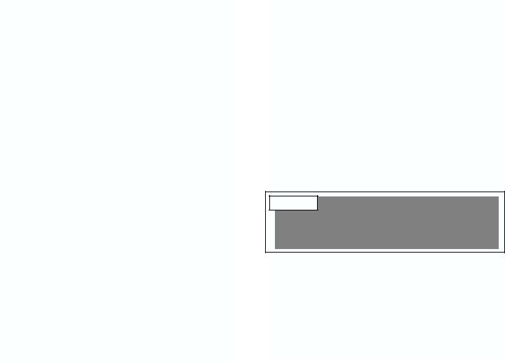
Holographic |
Removable Battery |
Window |
Compartment |
FIGURE 1
On/Off & Brightness |
Windage Adjustment |
Adjustments Switches |
|
Universal Mount |
Elevation Adjustment |
|
BASIC OPERATION
The BUSHNELL HOLOsight uses laser light to illuminate a holographic reticle pattern embedded in the heads-up display window and forms a virtual image of a reticle pattern. The shooter looks through the heads-up display window and sees a bright red image of a reticle pattern projected onto the target plane. There is absolutely no light projected onto the target plane, and the sight is legal to use in most shooting and hunting situations. The BUSHNELL HOLOsight has no magnification.
BATTERIES
Depending on the model, your Holosight is powered by either (2) N alkaline 1.5 V batteries or (2) AA batteries. An initial set of batteries comes with your sight. The BUSHNELL HOLOsight is designed to maintain constant brightness at a particular setting. The reticle brightness will not fade gradually as the batteries run down but rather shut down abruptly. The first indication of the batteries draining is the reticle blinking when the unit is turned on. Another indication of low batteries is the reticle pattern blinking off and on during recoil. With high recoil guns, this can occur before the battery check indicates low battery condition. If the reticle pattern blinks off and on during recoil or turns off suddenly, replace the batteries. Alkaline batteries from different manufacturers are not all constructed the same way. Tests show some brands are more susceptible to degradation by the shock of recoil.
Model 51-0021 – is powered by two N type 1.5 volt Alkaline batteries. We recommend the use of EVEREADY® ENERGIZER® batteries with the Bushnell HOLOsight in cold weather. Please note that there is a 12 Volt battery that is approximately the same size as the Type N 1.5 volt battery. DO NOT USE THE 12 VOLT BATTERY. It will severely damage your sight.
Model 52-0021 – is powered by two AA type 1.5 volt Alkaline batteries. The AA HOLOsight can utilize various types of batteries. Bushnell recommends Energizer batteries for regular use. NiMH rechargeable batteries are the most cost effective in the long run, but do need to be charged regularly as they do not hold a charge in storage well. For cold temperatures, Lithium AA batteries offer the longest battery life. However, please note that the battery test function which is designed to work with Alkaline batteries does not function accurately with Lithium batteries.
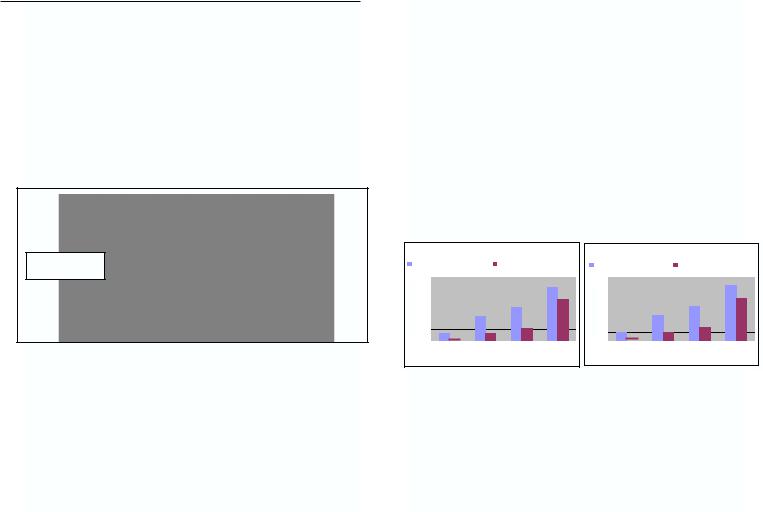
It is a good idea to change batteries before an extended hunting trip or match. For a comparison of battery life at various temperatures, please see the graphs :
Battery Life at Brightness Setting 12 |
|
Battery Life at Brightness Setting 20 |
|
|
|
Room Temp (21 deg C/70 deg F) Low Temp (-14 deg C/-7 deg F)) |
|
Room Temp (21 deg C/70 deg F) Low Temp (-14 deg C/-7 deg F) |
|
|
|
|
600 |
|
40 |
|
|
500 |
|
35 |
|
|
|
30 |
||
|
400 |
|
||
Hours |
Hours |
25 |
||
|
||||
300 |
20 |
|||
200 |
15 |
|||
|
|
|||
|
|
10 |
||
|
100 |
|
||
|
|
5 |
||
|
|
|
||
|
0 |
|
0 |
N Alkaline AA Alkaline |
AA NMHi |
AA Lithium |
N Alkaline |
AA Alkaline |
AA NMHi |
AA Lithium |
Battery Type |
|
|
Battery Type |
|
||
REPLACING BATTERIES
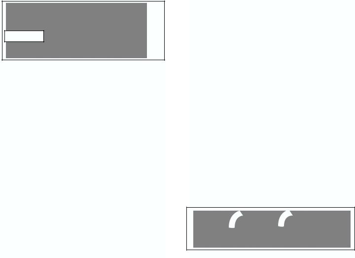
Remove the battery compartment by lifting up on the locking cam lever and carefully sliding the battery compartment away and up from the sight housing (Figure 2). After the battery compartment is removed, slide the batteries out and replace them with a fresh set. The labels on the bottom of battery compartment show the correct battery orientation. To re-install the battery compartment, point the sight towards the ground and slide battery compartment onto base. Make sure there is enough clearance between the contact and the batteries to avoid bending the contacts. Hold the battery compartment down firmly against the base and close the locking cam. Before you push down on the cam lever, make sure the battery compartment sits all the way down and parallel to the base. Verify correct battery installation immediately by turning on the sight and checking if the holographic reticle appears.
Directions to
Remove & Install Cam Lever
Battery Compartment
FIGURE 2
Tab on Base |
Battery Compartment |
2 |
|
3 |
ELECTRONIC FEATURES
All electronic controls are push-button switches located at the rear of the unit housing as shown in Figure 1. To ensure proper operation of the push button switches we recommend pressing firmly on the center of the switch.
1. ON/Auto Battery Check
Depressing the Up Arrow push-button switch will turn the sight ON. The sight will automatically perform a battery check every time it is turned on. If the batteries have less than 20% of life left, the sight will turn on with the reticle image blinking on and off for 5 seconds. If the remaining battery life is more than 20%, the sight will turn on with a steady reticle pattern. The battery condition can be checked any time by turning the sight off and back on.
2. OFF
To turn the sight off, depress both UP and DOWN arrows simultaneously. Verify by looking through heads-up display window.
3. Brightness Adjustment
Push-button switches vary the brightness intensity of the holographic reticle pattern. Depressing and releasing the push-button switches moves the brightness level UP or DOWN one (1) step from the previous setting. Depressing and holding the up arrow or down arrow switch will change brightness level up or down continuously in steps. There are twenty (20) brightness settings providing a dynamic range of 20,000:1 from the lowest setting to the highest setting. When the sight is turned ON, the brightness intensity level is automatically set to Level 12.
4. Auto Shutdown
The BUSHNELL HOLOsight is equipped with auto shutdown capability and will automatically shut itself OFF 8 hours after the last push-button control is used.
MOUNTING
The BUSHNELL HOLOsight is equipped with mounting hardware to attach to a standard 1" dovetail or Weaver® style rail. To achieve the best results and accuracy, the BUSHNELL HOLOsight must be mounted properly. The 1" dovetail rail needs to be as parallel as possible to the bore to achieve the best accuracy. We strongly recommend you have the dovetail rail installed by a qualified gunsmith. Should you decide to install the mount and sight yourself, please follow these steps:
1.Use a high-quality 1" steel dovetail rail mount designed to fit your particular firearm.
2.Carefully follow the instructions packed with the dovetail rail mount you have selected. Pay careful attention to aligning the dovetail base parallel to the bore of the firearm.
3.The dovetail base should be mounted as low as possible.
4.Locate the post and dovetail clamp on the underside of the sight. Loosen the hex nut retainer screw and the dovetail clamp with an Allen wrench (7/64).
5.Place the post within a groove on the top of the 1" dovetail base. Individual preference and the specific firearm determines the optimal positioning to any specific groove on the dovetail base.
6.Make sure the post is inserted fully into the mount’s groove and push the sight as far forward as possible. Tighten hex nut and retainer screw.
NOTE: Loosen screw just enough to mount and dis-mount the sight. Do not back screw out completely to avoid losing the Weaver lock hardware.
BORE SIGHTING AND ZEROING
Bore sighting is a good preliminary procedure in achieving proper alignment of your sight to the firearm. If the 1" dovetail rail is not mounted parallel to the barrel, major elevation adjustments may be accomplished by shimming the dovetail base. It is important not to use the elevation adjustment of the sight for major adjustments. Your sight’s internal elevation and windage adjustments should be reserved for fine-tuning to achieve zero at the called for distance. Final zeroing of your firearm and sight should be done with live ammunition and based on your expected shooting distance. If you anticipate most of your shooting at short range, zero in at 50 yards. Groups of three shots will be useful for averaging the point of impact.
WINDAGE AND ELEVATION ADJUSTMENTS
Your BUSHNELL HOLOsight features click mechanisms for elevation and windage adjustments. The elevation and windage adjustment are located on the right-hand side of the sight (Figure 1). The knob towards the front is your windage adjustment and the knob towards the rear is your elevation adjustment (Figure 1). Both of these adjustment mechanisms are grooved with a slotted screw head and require the use of a screwdriver, coin, or spent brass to turn.
The elevation and windage adjustments are shown in Figure 3. For both elevation and windage, each click will change the bullet’s point of impact 1/2 Minute of Angle (MOA), which translates to 1/4 inch at 50 yards, 1/2 inch at 100 yards. Also, one full rotation of either knob will change your point of impact 10 MOA. This translates into 5 inches at 50 yards, 10 inches at 100 yards. To move the point of impact UP, turn the adjustment screw counterclockwise; to move the point of impact DOWN, turn the adjustment screw clockwise.
Figure 3
Elevation |
Windage |
To move the point of impact RIGHT, turn the adjustment screw clockwise; to move the point of impact LEFT, turn the adjustment screw counterclockwise. The elevation and windage adjustments have been initially set at the factory near the midpoint of their adjustment ranges and should be close to being at zero with a properly installed mounting rail. Please do not turn the adjustments before mounting the sight on the firearm. Be sure to check that the mount and the sight remain secured after the first shots are fired.
CAUTION-When encountering a sudden increase in resistance in these adjustments, the end of the adjustment range has been reached. DO NOT TRY to turn the adjustments any farther or serious damage may occur to the sight.
4 |
|
5 |

LASER SAFETY ISSUES
The BUSHNELL HOLOsight is a Class II laser product. The Class II level illuminating beam, however, is completely blocked by the housing. The only laser light accessible to the eye is the image beam and is at a power level within the limit of a Class II laser product. The illuminating beam can become accessible to the eye if the housing is broken. Turn the sight off immediately and return the broken unit to the factory for repair.
FCC COMPLIANCE
The BUSHNELL HOLOsight complies with Part 15 of the FCC Rules. Operation is subject to the following conditions: (1) this device may not cause harmful interference and (2) this device must accept any interference received, including interference that may cause undesired operation.
MAINTENANCE AND CARE
Your BUSHNELL HOLOsight is a precision instrument that deserves reasonably cautious care. The following tips are provided to ensure long lasting use of the sight.
1.The optical system and the window are coated with anti-reflection material. When cleaning the glass surfaces, first blow away any dirt and dust. Fingerprints and lubricants can be wiped off with lens tissue or a soft cotton cloth, moistened with lens cleaning fluid or glass cleaner sold in any camera store.
Never clean the glass surface with a dry cloth or paper towel; always dampen the glass surfaces prior to cleaning.
2.All moving parts of the sight are permanently lubricated. Do not try to lubricate them.
3.No maintenance is needed on the sight’s surface, except to occasionally wipe off with a soft damp cloth. Use only a water-based cleaner such as glass cleaner, ammonia, or soap and water. Never use any solvent-type cleaner such as alcohol or acetone.
4.Never disassemble the sight’s optical assembly. The optical cavity is purged, nitrogen filled, and sealed to achieve fog proof performance. Disassembly will void the warranty.
TWO-YEAR LIMITED WARRANTY
Your Bushnell® product is warranted to be free of defects in materials and workmanship for two years after the date of purchase. In the event of a defect under this warranty, we will, at our option, repair or replace the product, provided that you return the product postage prepaid. This warranty does not cover damages caused by misuse, improper handling, installation, or maintenance provided by someone other than a Bushnell Authorized Service Department.
Any return made under this warranty must be accompanied by the items listed below:
1)A check/money order in the amount of $10.00 to cover the cost of postage and handling
2)Name and address for product return
3)An explanation of the defect
4)Proof of Date Purchased
5)Product should be well packed in a sturdy outside shipping carton, to prevent damage in transit, with return postage prepaid to the address listed below:
IN U.S.A. SEND TO: |
IN CANADA SEND TO: |
Bushnell Performance Optics |
Bushnell Performance Optics |
Attn.: Repairs |
Attn.: Repairs |
8500 Marshall Drive |
25A East Pearce Street, Unit 1 |
Lenexa, Kansas 66214 |
Richmond Hill, Ontario L4B 2M9 |
For products purchased outside the United States or Canada please contact your local dealer for applicable warranty information. In Europe you may also contact Bushnell at: BUSHNELL Performance Optics Gmbh
European Service Centre MORSESTRASSE 4
D- 50769 KÖLN GERMANY
Tél: +49 (0) 221 709 939 3 Fax: +49 (0) 221 709 939 8
This warranty gives you specific legal rights.
You may have other rights which vary from country to country. ©2003 Bushnell Performance Optics
6 |
|
7 |
FRENCH
Nous vous félicitons d’avoir choisi le BUSHNELL® HOLOsight®, un système de visée révolutionnaire, utilisant une technologie holographique avancée. Le viseur BUSHNELL HOLOsight facilite l’acquisition de cible, accroît la précision et permet de mieux contrôler l’environnement de tir.
Le viseur BUSHNELL HOLOsight répond aux besoins de tous les tireurs, du novice au professionnel le plus chevronné. Notre objectif est d’offrir à chacun de nos clients le niveau de qualité, d’engagement et de service, qu’ils sont en droits d’attendre du leader de l’industrie des systèmes de visée. Quelle que soit votre discipline de tir, nous vous souhaitons le plus grand succès et, encore une fois, vous remercions pour votre choix d’un viseur BUSHNELL HOLOsight.
Veillez à lire les instructions attentivement avant de monter le viseur et n’oubliez pas de toujours respecter les règles de sécurité des armes à feu.
Inclus: Viseur, 2 piles alcalines AA ou N
Une clé Allen de 7/64 est nécessaire pour l’installation
Fenêtre |
Compartiment de |
holographique |
piles amovible |
FIGURE 1
Commutateur marche/arrêt |
Réglage de dérive |
et réglage de luminosité |
|
Monture universelle |
Réglage d’élévation |
|
PRINCIPE DE FONCTIONNEMENT
Le viseur BUSHNELL HOLOsight utilise un laser pour illuminer un graphisme intégré dans la fenêtre d’affichage tête haute et former une image virtuelle de réticule. Lorsque le tireur regarde dans la fenêtre d’affichage tête haute, il voit l’image lumineuse d’un réticule projetée sur la cible. Aucune lumière n’est projetée sur la cible et le viseur peut être utilisé légalement dans la plupart des situations de chasse et de tir sur cible. Le viseur BUSHNELL HOLOsight n’utilise aucun système de grossissement.
PILES
Suivant le modèle, le viseur HOLOsight fonctionne sur (2) piles alcalines N de 1,5 V, ou (2) piles AA. Un jeu de piles initial est inclus avec le viseur. Le viseur BUSHNELL HOLOsight est conçu pour maintenir un niveau de luminosité constant, à un réglage donné. La luminosité du réticule de diminue pas progressivement à mesure de la décharge des piles, il s’éteint complètement lorsque la charge est insuffisante. La première indication de faiblesse de charge est un clignotement du réticule lorsque le système est allumé. Une autre indication
de faiblesse de charge est un clignotement du réticule pendant le recul. Dans le cas d’une arme à fort recul, ceci peut ce produire avant que le système de vérification de pile indique une faible charge. Si le réticule clignote pendant le recul ou ‘disparaît brusquement, remplacer les piles. Les piles alcalines provenant de différents fabricants ne sont pas toutes construites de la même façon. Des test ont prouvé que les piles de certaines marques sont plus affectées par le choc du recul que d’autres.
Le modèle 510021 fonctionne sur deux piles alcalines N de 1,5 V. Si le viseur Bushnell HOLOsight est utilisé par temps froid, nous recommandons l’usage de piles EVEREADY® ENERGIZER®. Noter qu’il existe une pile 12 volts dont la taille est presque la même que celle des piles 1,5 volt. NE PAS UTILISER DE PILES 12 VOLTS. Ces piles endommageraient sérieusement le viseur.
Le modèle 520021 fonctionne sur deux piles alcalines AA de 1,5 V. Le viseur HOLOsight AA peut utiliser différents types de piles. Pour l’usage général, Bushnell recommande les piles Energizer. Les piles NiMH rechargeables sont les plus économiques à long terme, mais elles doivent être rechargées régulièrement car leur autonomie est moindre. À basses températures, les piles AA au lithium sont les plus durables. Il convient toutefois de noter que le fonctionnement du testeur de charge ,conçu pour les piles alcalines, est imprécis avec les piles au lithium.
Il est recommandé de changer les piles avant une partie de charge ou un concours de tir de longue durée. Pour une comparaison de l’autonomie des piles à différentes températures, consulter les graphiques :
|
|
AUTONOMIE DES PILES AVEC UN |
|
|
|
|
AUTONOMIE DES PILES AVEC UN |
|
|||||
|
|
Battery Life at Brightness Setting 12 |
|
|
|
|
Battery Life at Brightness Setting 20 |
|
|||||
|
|
RÉGLAGE DE LUMINOSITÉ DE 12 |
|
|
|
|
RÉGLAGE DE LUMINOSITÉ DE 20 |
|
|||||
|
|
|
|
|
|
|
|
|
|
|
|
|
|
|
TempRoomératureTeambiante(21p (21 degdegréC/70s C / 70degregésF)F) |
|
BasseLowtempTempérature(-14(-14ddegréC/s C-/77 degregésFF)) |
|
|
TempRoomératureTeambiante(21p (21 degdegréC/70s C / 70 degregésF)F) |
|
BasseLowtempTempérature(-14(-14degdegréC/s C-7/ 7degregéF)s F) |
|
||||
|
|
|
|
|
|
|
|
|
|
|
|
|
|
|
600 |
|
40 |
|
|
500 |
|
35 |
|
|
|
30 |
||
|
400 |
|
||
Hours |
Heuresours |
25 |
||
|
||||
300 |
20 |
|||
|
15 |
|||
Heures |
200 |
|||
|
|
10 |
||
|
100 |
|
||
|
|
5 |
||
|
|
|
||
|
0 |
|
0 |
NNalcalineAlkaline AAAAalcalineAlkaline AAAANiMHN Hi AA lithiumLithi |
|
NNalcalineAlkaline AA alcalineAlkali |
AA NiMHHi |
AA Lilithium |
||||
|
|
|
|
|
|
|
|
|
|
BatteryType deTypepile |
|
|
|
BattTyperydeTypepile |
|
|
|
REMPLACEMENT DES PILES
Retirer le compartiment à piles. Pour ce faire, relever le lever de verrouillage à came et sortir le compartiment du corps du viseur en le tirant avec précaution vers le haut (figure 2). Ceci fait, retirer les piles du compartiment et les remplacer par un jeu neuf. L’autocollant situé au bas du compartiment montre l’orientation correcte des piles. Pour remettre le compartiment des piles en place, pointer le viseur vers le sol et glisser le compartiment sur la base. S’assurer que l’espace entre les contacts et les piles est suffisant pour éviter de tordre les contacts. Serrer fermement le compartiment à piles contre la base et fermer la came de verrouillage. Avant d’abaisser le levier à came, vérifier que le compartiment à piles est inséré bien à fond et parallèle à la base. Vérifier immédiatement si les piles sont correctement installées en allumant ;e viseur pour voir si le réticule holographique apparaît.
8 |
|
9 |
Retrait et remise |
|
|
en place du |
Levier à came |
|
compartiment à piles |
||
|
FIGURE 2
Languette de la base Compartiment à piles
FONCTIONS ÉLECTRONIQUES
Toutes les fonctions électroniques sont commandées par des boutons poussoirs situés à l’arrière du viseur, comme le montre la figure 1.
1.MARCHE/vérification automatique de pile
Appuyer sur le bouton fléché vers le haut pour allumer le viseur. Le viseur effectue automatiquement une vérification des piles lorsqu’il est allumé. Si l’autonomie de pile restante est de moins de 20 %, l’image de réticule clignote pendant 5 secondes lorsque le viseur est allumé. Si l’autonomie de pile restante est de moins de 20 %, l’image de réticule reste fixe. La charge des piles peut être vérifiée à tout moment en éteignant et rallumant le viseur.
2.ARRÊT
Pour éteindre le viseur, appuyer simultanément sur les boutons fléchés vers le HAUT et vers le BAS. Vérifier que le viseur est éteint en regardant dans la fenêtre tête haute.
3.Réglage de luminosité
Des boutons poussoirs permettent de régler l’intensité lumineuse du réticule holographique. Appuyer sur les boutons fléchés et les relâcher immédiatement pour AUGMENTER ou RÉDUIRE la luminosité d’un (1) niveau. Maintenir le bouton fléché vers le haut ou vers le bas pour obtenir le défilement continu des niveaux de luminosité. Le viseur offre vingt (20) niveaux de réglage, représentant une plage de 20 000:1 entre les niveau 1 et 20. Lorsque le viseur est allumé, le niveau d’intensité lumineuse se règle automatiquement sur 12.
4.Arrêt automatique
Le viseur BUSHNELL HOLOsight est doté d’une fonction d’arrêt automatique, qui l’éteint automatiquement 8 heures après que le dernier bouton ait été enfoncé.
MONTAGE
Le viseur BUSHNELL HOLOsight est fourni avec la quincaillerie de montage nécessaire pour l’installer sur un rail à queue d’aronde standard de 1 po(25 mm) ou de type Weaver®. Pour assurer des résultats et une précision optimum, le viseur BUSHNELL HOLOsight doit être monté correctement. Pour obtenir une précision maximum, le rail à queue d’aronde de 25 mm doit être aussi parallèle que possible au canon. Nous recommandons vivement de faire installer le rail à queue d’aronde par un armurier qualifié. Pour installer et régler la monture soi-même, procéder comme suit :
1.Utiliser un rail à queue d’aronde de 25 mm de haute qualité, compatible avec l’arme.
2.Suivre attentivement les instructions fournies avec le rail sélectionné. Veiller particulièrement à bien aligner le rail à queue d’aronde sur le canon de l’arme.
3.Le rail doit être monté aussi bas que possible.
4.Localiser le goujon et la bride à queue d’aronde du dessous du viseur. Desserrer la vis de retenue hexagonale et la bride au moyen d’une clé Allen de 7/64.
5.Placer le goujon dans une rainure du rail à queue d’aronde. Le choix de la rainure de la base à queue d’aronde est une question de préférence personnelle et de configuration de l’arme.
6.S’assurer que le goujon est engagé à fond dans la rainure et pousser le viseur aussi loin vers l’avant que possible. Serrer l’écrou hexagonal et la vis de retenue.
REMARQUE : desserrer la vis juste assez pour permettre de monter ou démonter le viseur. Ne pas la dévisser complètement afin d’éviter de perdre la quincaillerie de montage Weaver.
POINTAGE ET ZÉROTAGE
Le pointage est un bon point de départ pour obtenir un alignement correct du viseur sur l’arme. Si le rail à queue d’aronde de 25 mm n’est par monté parallèle au canon, les réglages d’élévation importants peuvent être effectués au moyen de cales. Il est essentiel de ne pas utiliser le réglage d’élévation de pointage pour les réglages importants. Les réglages interne d’élévation et de dérive du viseur doivent être réservés pour un ajustement fin, destiné à obtenir le zérotage à une distance donnée. Le zérotage final de l’arme et du viseur doit être effectué avec des balles réelles, en fonction de la distance de tir prévue. Si la plupart des tirs doivent être effectués à courte distance, zéroter à 50 mètres. Les groupages de 3 balles facilitent la détermination de la moyenne de point d’impact.
RÉGLAGES DE DÉRIVE ET D’ÉLÉVATION
Le viseur BUSHNELL HOLOsight est doté de mécanismes à cliquet pour les réglages d’élévation et de dérive. Ces mécanismes se trouvent du côté droit du viseur (figure 1). Le bouton avant est celui de réglage de la dérive, et le bouton arrière celui de réglage d’élévation (figure 1). Ces deux mécanismes de réglage sont dotés d’une vis à tête fendue qui nécessite un tournevis, une pièce de monnaie ou une douille vide pour être tournée.
Les réglages d’élévation et de dérive sont représentés à la figure 3. Pour les deux réglage, chaque déclic correspond à 1/2 minute d’angle, ce qui correspond à 13 mm à 50 mètres et 25 mm à 100 mètres. Un tour complet de l’un ou l’autre des boutons change le point d’impact de 10 minutes d’angle. Ceci représente 13 cm à 50 mètres et 25 cm à 100 mètres. Pour ÉLEVER le point d’impact, tourner la vis de réglage dans le sens antihoraire, pour l’ABAISSER, tourner la vis dans le sens horaire.
|
|
|
|
|
|
|
|
t |
|
|
|
|
Figure 3 |
|
|
|
|
|
|
n |
|
|
|
|
|
|
|
|
|
|
e |
|
|
|
|
i |
||
|
|
|
|
e |
|
|
|
|
|
|||
|
|
|
|
|
|
m |
|
|
|
|
|
e |
|
|
|
|
s |
|
|
|
|
|
o |
||
|
|
|
s |
|
|
|
|
|
|
r |
|
|
|
b |
a |
i |
|
|
|
|
|
À |
d |
|
|
|
|
|
|
|
|
|
|
|
||||
Élévation |
A |
|
|
|
|
|
|
|
|
|
Dérive |
|
|
|
|
|
|
|
|
|
|
|
|||
|
|
|
|
|
|
|
|
|
|
|
||
10 |
|
11 |
 Loading...