


BUSH HOG®
Model 3860 QT
Front End Loader
Operator’s Manual
OPERATION • MAINTENANCE
208 |
$4.00 |
25H51137 |

CONGRATULATIONS!
You have invested in the best implement of its type on the market today.
The care you give your Bush Hog implement will greatly determine your satisfaction
with its performance and its service life. We urge a careful study of this manual to provide you with a thorough understanding of your new implement before operating, as well as suggestions for operation and maintenance.
If your manual should become lost or destroyed, Bush Hog will be glad to provide you with a new copy. Order from Bush Hog, P. O. Box 1039, Selma, Alabama 36702-1039.
As an authorized Bush Hog dealer, we stock genuine Bush Hog parts which are manufactured with the same precision and skill as our original equipment. Our trained service personnel are well informed on methods required to service Bush Hog equipment, and are ready and able to help you.
Should you require additional information or assistance, please contact us.
YOUR AUTHORIZED
BUSH HOG DEALER
BECAUSE BUSH HOG MAINTAINS AN ONGOING
PROGRAM OF PRODUCT IMPROVEMENT, WE
RESERVE THE RIGHT TO MAKE IMPROVEMENTS IN
DESIGN OR CHANGES IN SPECIFICATIONS WITH-
OUT INCURRING ANY OBLIGATION TO INSTALL
THEM ON UNITS PREVIOUSLY SOLD.
BECAUSE OF THE POSSIBILITY THAT SOME
PHOTOGRAPHS IN THIS MANUAL WERE TAKEN OF
PROTOTYPE MODELS, PRODUCTION MODELS MAY
VARY IN SOME DETAIL. IN ADDITION, SOME
PHOTOGRAPHS MAY SHOW SHIELDS REMOVED
FOR PURPOSES OF CLARITY. NEVER OPERATE
THIS IMPLEMENT WITHOUT ALL SHIELDS IN PLACE.

3860 QT
TABLE OF CONTENTS
SECTION |
PAGE |
|
|
Warranty ..................................................................... |
2 |
|
Dealer Preparation Check List.................................... |
3 |
|
Safety Precautions ..................................................... |
4 |
|
Federal Laws & Regulations....................................... |
6 |
1. |
INTRODUCTION & DESCRIPTION ........................... |
7 |
|
Introduction................................................................. |
7 |
|
Description.................................................................. |
7 |
|
Technical Specifications ............................................. |
8 |
2. |
INSTALLATION INSTRUCTIONS .............................. |
9 |
|
Tractor Preparation..................................................... |
9 |
|
Installation .................................................................. |
9 |
|
Quick Draw Latch Attach .......................................... |
10 |
|
Torque Identification ................................................. |
11 |
3. |
PRE-OPERATION INSTRUCTIONS........................ |
12 |
|
Transmission Fluid ................................................... |
12 |
|
Initial Loader Operation ............................................ |
12 |
|
External Loader and/or Tractor Valve....................... |
12 |
|
Neutral Position ........................................................ |
13 |
|
Float Position............................................................ |
13 |
|
Initial Loader Operation ............................................ |
13 |
|
Removing Air From Hydraulic System...................... |
13 |
|
Hose Identification .................................................... |
13 |
|
Bucket Level INdicator.............................................. |
13 |
|
Remote Hoses Support ............................................ |
14 |
|
Third Cylinder Tube Kit............................................. |
14 |
4. |
MAINTENANCE ....................................................... |
15 |
|
Daily Checks............................................................. |
15 |
|
Loader Lubrication.................................................... |
15 |
|
Quick Draw Latch Attach Lubrication ....................... |
16 |
5. |
OPERATING INSTRUCTIONS ................................ |
16 |
SECTION |
PAGE |
|
|
General Safety.......................................................... |
16 |
|
Bucket Level Indicator .............................................. |
16 |
|
Operation.................................................................. |
16 |
|
Handling Large Heavy Objects................................. |
21 |
|
Back Grading............................................................ |
21 |
|
Troubleshooting........................................................ |
22 |
6. |
DISMOUNTING THE LOADER ................................ |
23 |
7. |
MOUNTING THE LOADER ...................................... |
25 |
8. |
INSTALLATION & OPERATION OF |
|
|
QUICK DRAW LATCH ATTACH .............................. |
27 |
|
Installation Instructions ............................................. |
27 |
|
Operating Instructions .............................................. |
27 |
9. |
INSTALLING BUCKET OR ATTACHMENT |
|
|
TO QUICK DRAW LATCH ATTACH ........................ |
29 |
|
Operating Instructions .............................................. |
29 |
10. |
REMOVING BUCKET OR ATTACHMENT |
|
|
FROM QUICK DRAW LATCH ATTACH .................. |
31 |
|
Operating Instructions .............................................. |
31 |
11. |
BUCKET ATTACHMENT ......................................... |
32 |
|
Quick Draw Bucket ................................................... |
32 |
|
Single Tine Kit .......................................................... |
32 |
12. |
SUPER PENETRATOR BALE PROBE |
|
|
ATTACHMENT ......................................................... |
33 |
|
Installation Instructions ............................................. |
33 |
|
Operating Instructions .............................................. |
33 |
13. |
DOZER ATTACHMENT ........................................... |
34 |
14. |
MANURE FORK ATTACHMENT ............................. |
34 |
15. |
PALLET FORK ATTACHMENT................................ |
35 |
16. |
GRAPPLE ATTACHMENT ....................................... |
36 |
Safety Decals.................................................................. |
41 |
|
Torque Specifications ..................................................... |
43 |
|
RETAIL CUSTOMER’S RESPONSIBILITY
UNDER THE BUSH HOG WARRANTY
It is the Retail Customer and/or Operator’s responsibility to read the Operator’s Manual, to operate, lubricate, maintain and store the product in accordance with all instructions and safety procedures. Failure of the operator to read the Operator’s Manual is a misuse of this equipment.
It is the Retail Customer and/or Operator’s responsibility to inspect the product and to have any part(s) repaired or replaced when continued operation would cause damage or excessive wear to other parts or cause a safety hazard.
It is the Retail Customer’s responsibility to deliver the product to the authorized Bush Hog Dealer, from whom he purchased it, for service or replacement of defective parts which are covered by warranty. Repairs to be submitted for warranty consideration must be made within forty-five (45) days of failure.
It is the Retail Customer’s responsibility for any cost incurred by the Dealer for traveling to or hauling of the product for the purpose of performing a warranty obligation or inspection.
1

LIMITED WARRANTY
OOOOOOOOOOOOOOOOOOOOOOOOOOOOOOO
Bush Hog warrants to the original purchaser of any new Bush Hog equipment, purchased from an authorized Bush Hog dealer, that the equipment be free from defects in material and workmanship for a period of one (1) year for non-commercial, state, and municipalities’ use and ninety (90) days for commercial use from date of retail sale. The obligation of Bush Hog to the purchaser under this warranty is limited to the repair or replacement of defective parts.
Replacement or repair parts installed in the equipment covered by this limited warranty are warranted for ninety (90) days from the date of purchase of such part or to the expiration of the applicable new equipment warranty period, whichever occurs later. Warranted parts shall be provided at no cost to the user at an authorized Bush Hog dealer during regular working hours. Bush Hog reserves the right to inspect any equipment or parts which are claimed to have been defective in material or workmanship.
DISCLAIMER OF IMPLIED WARRANTIES & CONSEQUENTIAL DAMAGES
Bush Hog’s obligation under this limited warranty, to the extent allowed by law, is in lieu of all warranties, implied or expressed, INCLUDING IMPLIED WARRANTIES OF MERCHANTABILITY AND FITNESS FOR A PARTICULAR PURPOSE and any liability for incidental and consequential damages with respect to the sale or use of the items warranted. Such incidental and consequential damages shall include but not be limited to: transportation charges other than normal freight charges; cost of installation other than cost approved by Bush Hog; duty; taxes; charges for normal service or adjustment; loss of crops or any other loss of income; rental of substitute equipment, expenses due to loss, damage, detention or delay in the delivery of equipment or parts resulting from acts beyond the control of Bush Hog.
THIS LIMITED WARRANTY SHALL NOT APPLY:
1.To vendor items which carry their own warranties, such as engines, tires, and tubes.
2.If the unit has been subjected to misapplication, abuse, misuse, negligence, fire or other accident.
3.If parts not made or supplied by Bush Hog have been used in connection with the unit, if, in the sole judgement of Bush Hog such use affects its performance, stability or reliability.
4.If the unit has been altered or repaired outside of an authorized Bush Hog dealership in a manner which, in the sole judgement of Bush Hog, affects its performance, stability or reliability.
5.To normal maintenance service and normal replacement items such as gearbox lubricant, hydraulic fluid, worn blades, or to normal deterioration of such things as belts and exterior finish due to use or exposure.
6.To expendable or wear items such as teeth, chains, sprockets, belts, springs and any other items that in the company’s sole judgement is a wear item.
NO EMPLOYEE OR REPRESENTATIVE OF BUSH HOG IS AUTHORIZED TO CHANGE THIS LIMITED WARRANTY IN ANY WAY OR GRANT ANY OTHER WARRANTY UNLESS SUCH CHANGE IS MADE IN WRITING AND SIGNED BY BUSH HOG’S SERVICE MANAGER, POST OFFICE BOX 1039, SELMA, ALABAMA 36702-1039.
OOOOOOOOOOOOOOOOOOOOOOOOOOOOOOO
Record the model number, serial number and date purchased. This information will be helpful to your dealer if parts or service are required.
MAKE CERTAIN THE WARRANTY REGISTRATION CARD HAS BEEN FILED WITH BUSH HOG/
MODEL NUMBER
SERIAL NUMBER
SELMA, ALABAMA |
DATE OF RETAIL SALE |
2

DEALER PREPARATION CHECK LIST
3860 QT LOADER
BEFORE DELIVERING MACHINE - The following check list should be completed. Use the Operator’s Manual as a guide.
Machine properly assembled.
All safety decals readable. (See decal page)
All bolts tightened to torque specifications given in torque chart.
Machine operates properly.
Customer has appropriate mounting kit for his tractor and loader.
Customer has appropriate attachments for loader operations. ( Buckets for lifting loose materials; bale spear for lifting round bales; fork lift for lifting palletized material)
 CAUTION
IT IS RECOMMENDED THAT TRACTOR BE
EQUIPPED WITH ROLLOVER PROTECTIVE SYS-
TEM (ROPS) AND SEAT BELT BE USED FOR ALL
LOADER OPERATIONS.
Operators manual has been delivered to owner and he has been instructed on the safe and proper use of the front end loader.
Dealer’s Signature
THIS CHECK LIST TO REMAIN IN OPERATOR’S MANUAL
It is the responsibility of the dealer to complete the procedures listed above before delivery of this implement to the customer.
3

IMPORTANT SAFETY PRECAUTIONS
This symbol is used to call attention to safety precautions that should be followed by the operator to avoid accidents. When you see this symbol, carefully read the message that follows and heed its advice. Failure to comply with safety precautions could result in serious bodily injury.
In addition to the design and configuration of equipment, hazard control and accident prevention are dependent upon the awareness, concern, prudence and proper training of personnel in the operation, transport, maintenance and storage of equipment. Lack of attention to safety can result in accident, personal injury, reduction of efficiency and worst of all—loss of life. Watch for safety hazards and correct deficiencies promptly. Use the following safety precautions as a general guide to safe operations when using this machine. Additional safety precautions are used throughout this manual for specific operating and maintenance procedures. Read this manual and review the safety precautions often until you know the limitations.
THE TRACTOR
1.Read the tractor operator’s manual to learn how to operate your tractor safely. Failure to do so could result in serious injury or death and equipment damage.
2.It is recommended that tractor be equipped with Rollover Protective System (ROPS) and a seat belt be used for all loader operations.
3.Add wheel ballast or rear weight for stability.
4.Move wheels to the tractor manufacturer’s widest recommended settings to increase stability.
5.For better stability, use tractor with wide front axle rather than tricycle front wheels.
6.Move and turn the tractor at low speeds.
7.Stop tractor engine, place transmission in park (or neutral), engage parking brake, lower loader arms to ground, cycle all hydraulic controls to relieve pressure, allow machine moving parts to stop, remove ignition key to prevent unauthorized person from starting engine before dismounting tractor or servicing, repairing, or making adjustments to the equipment.
8.Wear personal protective equipment (PPE), such as, but not limited to, protection for eyes, ears, lungs, head, hands and feet when operating, servicing, or repairing equipment. Avoid wearing loose clothing or jewelry that may catch and entangle on equipment moving parts.
THE LOADER
1.Read the loader operator’s manual to learn how to operate your loader safely. Failure to do so could result in serious injury or death and equipment damage.
2.Become familiar with all the machine’s controls and all the caution, warning and danger decals affixed to the machine before attempting to start or operate.
3.Improper use of a loader can cause serious injury or death.
4.Do not lift or carry anybody on the loader or in the bucket or attachment.
5.Never allow anyone to get under the loader bucket or reach through the booms when the bucket is raised.
6.Do not walk or work under a raised loader bucket or attachment unless it is is securely blocked or held in position.
7.Avoid overhead wires and obstacles when loader is raised. Contacting electrical lines can cause electrocution.
8.Make sure all parked loaders on stands are on a hard, level surface.
9.Use a piece of cardboard or wood rather than hands and wear eye protection when searching for hydraulic leaks. Escaping hydraulic oil under pressure can penetrate skin. If oil is injected into skin, it must be surgically removed within a few hours by a doctor or gangrene may result.
4

SAFETY PRECAUTIONS CONTINUED
10.Before disconnecting hydraulic lines, relieve all hydraulic pressure.
11.Do not tamper with the relief valve setting. The relief valve is pre-set at the factory. Changing the setting can cause overloading the loader and tractor and serious operator injury may result.
12.Always wear safety goggles when repairing or servicing machine.
13.When servicing or replacing pins in cylinder ends, buckets, etc., always use a brass drift and hammer. Failure to do so could result in injury from flying fragments.
14.Replace damaged or illegible safety decals. See decal page for required decals.
15.Do not modify or alter or permit anyone else to modify or alter the loader, any of its components or any loader function without first consulting your local dealer.
OPERATING THE LOADER
1.It is the loader owner’s responsibility to instruct and have a person read operator’s manual, safety decals and become familiar with machine controls before allowing them to operate loader.
2.Do not allow children to operate the loader.
3.Before starting or operating the equipment, make a walk around inspection and check for loose or damaged components. Correct any deficiency before starting.
4.Keep the area of operation clear of all persons, particularly small children. The operator should cease operation whenever anyone comes within the operating area.
5.Operate the loader from the “Operator’s Seat Only.”
6.Exercise caution when operating the loader with a raised loaded bucket or fork.
7.Avoid loose fill, rocks and holes. They can be dangerous for loader operation or movement.
8.Be extra careful when working on inclines.
9.Allow for the loader length when making turns.
10.Stop the loader arms gradually when lowering or lifting.
11.Use caution when handling loose or shiftable loads.
12.Carry loader arms at a low position during transport.
13.Lower loader arms, stop engine, and lock brakes before leaving the tractor seat.
14.Operate the loader controls only when properly seated at the controls.
15.Do not use loader for handling large, heavy objects such as logs, oil drums, etc.
16.Handling large, heavy objects is dangerous due to: *Possibility of rolling the tractor over.
*Possibility of upending the tractor.
*Possibility of the object rolling or sliding down the loader arms onto the operator.
17.Use large round hay bale handler attachment with bale retaining devices (grapples, bale spears, clamps, etc.) to handle large round hay bales. Failure to use retaining devices could allow round hay bales to roll or fall down loader boom arms onto the operator causing serious injury or death and equipment damage.
5

IMPORTANT FEDERAL LAWS AND REGULATIONS* CONCERNING
EMPLOYERS, EMPLOYEES AND OPERATIONS.
*(This section is intended to explain in broad terms the concept and effect of the following federal laws and regulations. It is not intended as a legal interpretation of the laws and should not be considered as such).
U.S. Public Law 91-596 (The Williams-Steiger Occupational and Health Act of 1970) OSHA
This Act Seeks:
“...to assure so far as possible every working man and woman in the nation safe and healthful working conditions and to preserve our human resources...”
DUTIES
Sec. 5 (a) Each employer—
(1)shall furnish to each of his employees employment and a place of employment which are free from recognized hazards that are causing or are likely to cause death or serious physical harm to his employees;
(2)shall comply with occupational safety and health standards promulgated under this Act.
(b)Each employee shall comply with occupational safety and health standards and all rules, regulations and orders issued pursuant to this Act which are applicable to his own actions and conduct.
OSHA Regulations
Current OSHA regulations state in part: “At the time of initial assignment and at least annually thereafter, the employer shall instruct every employee in the safe operation and servicing of all equipment with which the employee is, or will be involved.” These will include (but are not limited to) instructions to:
Keep all guards in place when the machine is in operation;
Permit no riders on equipment;
Stop engine, disconnect the power source, and wait for all machine movement to stop before servicing, adjusting, cleaning or unclogging the equipment, except where the machine must be running to be properly serviced or maintained, in which case the employer shall instruct employees as to all steps and procedures which are necessary to safely service or maintain the equipment.
Make sure everyone is clear of machinery before starting the engine, engaging power, or operating the machine.
EMPLOYEE TRACTOR OPERATING INSTRUCTIONS:
1.Securely fasten your seat belt if the tractor has a ROPS.
2.Where possible, avoid operating the tractor near ditches, embankments, and holes.
3.Reduce speed when turning, crossing slopes, and on rough, slick, or muddy surfaces.
4.Stay off slopes too steep for safe operation.
Child Labor Under 16 Years Old
5.Watch where you are going, especially at row ends, on roads, and around trees.
6.Do not permit others to ride.
7.Operate the tractor smoothly - no jerky turns, starts, or stops.
8.Hitch only to the drawbar and hitch points recommended by tractor manufacturers.
9.When tractor is stopped, set brakes securely and use park lock if available.
Some regulations specify that no one under the age of 16 may operate power machinery. It is your responsibility to know what these regulations are in your own area or situation. (Refer to U.S. Dept. of Labor, Employment Standard Administration, Wage & Home Division, Child Labor Bulletin #102.)
6
1. INTRODUCTION AND DESCRIPTION
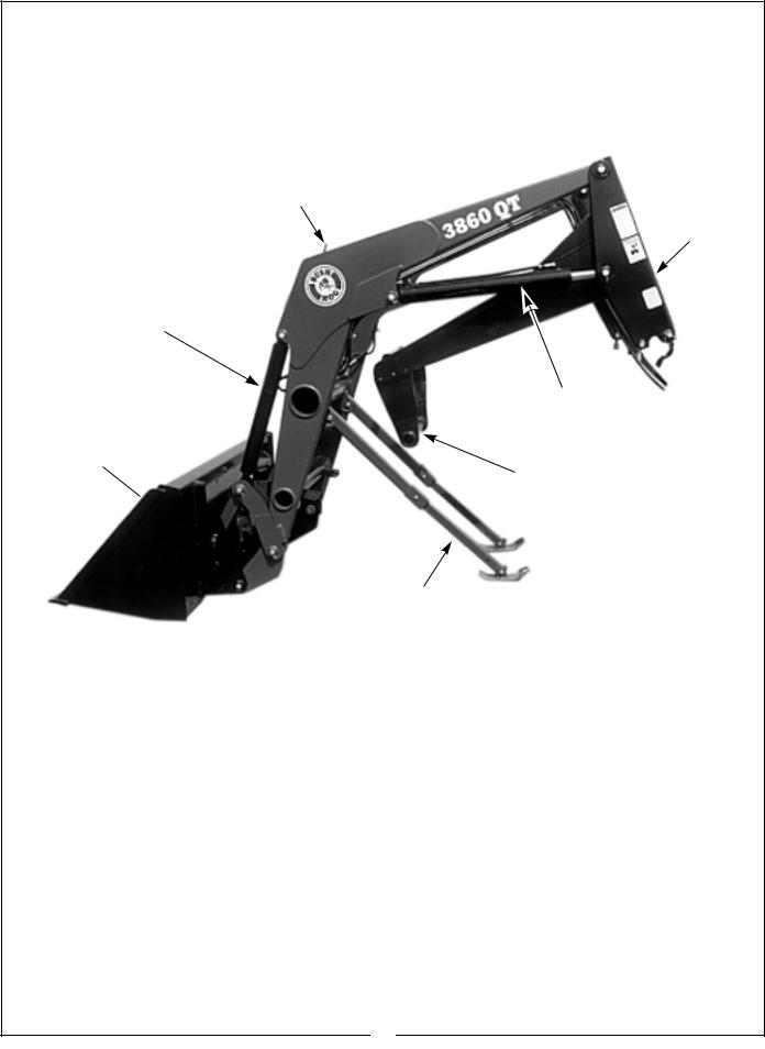
Figure 1 Major Components
Gauge Rod
Subframe
Bucket Cylinder
Boom Cylinder
Bucket
Cross Tube
Parking Stand
INTRODUCTION
We are pleased to have you as a Bush Hog customer. Your Front End Loader has been carefully designed to give maximum service with minimum down time. This manual is provided to give you the necessary operating and maintenance instructions for keeping your front end loader in top operating condition. Please read this manual thoroughly. Understand what each control is for and how to use it. Observe all safety precautions decaled on the machine and noted throughout the manual for safe operation of implement. If any assistance or additional information is needed, contact your authorized Bush Hog dealer.
NOTE
All references made to right, left, front, rear, top or bottom is as viewed facing the direction of forward travel with implement properly attached to tractor.
DESCRIPTION
The model 3860 Front End Loader (Figure 1) is designed for two and four wheel drive tractors. It comes equipped with parking stands to support loader so tractor can be “driven in” for quick attachment, optional hydraulic self leveling for maintaining the load in position during the raising and lowering cycle and a bucket level indicator that allows operator to gauge bucket position when bucket cannot be seen. Available attachments include buckets for lifting loose materials; a bale spear for lifting round hay bales; a grapple attachment for handling bulky materials; a dozer for pushing; and a fork lift for palletized material. All operations should be conducted within the loader limits specified in Technical Specifications.
7
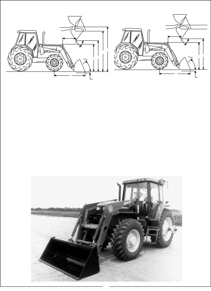
Model 3860 QT Technical Specifications
D |
|
|
D |
|
|
|
E |
|
|
|
E |
|
|
|
|
|
|
|
|
|
|
|
A |
|
|
|
|
B |
|
|
|
C |
J |
C |
|
J |
|
||
|
|
|
||
|
|
|
|
|
|
G |
|
G |
|
|
|
|
|
|
|
F |
|
F |
|
|
|
H |
|
|
|
H |
|
|
|
|
|
|
|
A. |
Maximum Lift Height - Measured at Pivot Pin |
. . . .176" |
B. |
Maximum Lift Height - Under Level Bucket . . . . . 170" |
|
C. |
Clearance with Attachment Dumped 45º . . . . |
. . . 148" |
D. |
Reach at Maximum Height . . . . . . . . . . . . . . . . |
. . . . 33” |
E. |
Maximum Dump Angle . . . . . . . . . . . . . . . . . . . |
. . . . 34° |
F. |
Reach with Bucket on Ground . . . . . . . . . . . . |
. . . . 89” |
G. |
Maximum Rollback Angle . . . . . . . . . . . . . . . . . |
. . . 19° |
H. |
Digging Depth . . . . . . . . . . . . . . . . . . . . . . . . |
. . . . 5” |
J. |
Overall Height in Carry Position . . . . . . . . . . . . |
. . . 81” |
U. |
Lift Capacity to Maximum Height - At Pivot Pin . . |
4580 lbs. |
V. |
Lift Capacity to Maximum Height - |
|
|
31.5” Forward of Pivot Pin . . . . . . . . . . . . . . . . . . . |
3680 lbs. |
W. Lift Capacity to 59” Height - At Pivot Pin . . . . . . . |
7100 lbs. |
|
X. |
Lift Capacity to 59” Height - |
|
|
31.5” Forward of Pivot Pin . . . . . . . . . . . . . . . . . . . |
4970 lbs. |
Y. |
Breakout Force - At Pivot Pin . . . . . . . . . . . . . . . . |
8400 lbs. |
Z. |
Breakout Force - 31.5” Forward of Pivot Pin . |
6050 lbs. |
VV. |
Rollback Force at Maximum Height - |
|
|
31.5” Forward of Pivot Pin . . . . . . . . . . . . . . . |
7706lbs. |
XX. |
Rollback Force at 59” Height - |
|
|
31.5” Forward of Pivot Pin . . . . . . . . . . . . . . |
6787 lbs. |
ZZ. |
Rollback Force at Ground Level - |
|
|
31.5” Forward of Pivot Pin . . . . . . . . . . . . . . |
5250 lbs. |
|
Raising Time - Ground Level to Full Height . . |
5.7 sec. |
|
Lowering Time - Full Height to Ground Level . |
5.1 sec. |
|
Bucket Dumping Time - Full Rollback |
|
|
to Full Dump . . . . . . . . . . . . . . . . . . . . . . . . . . . |
3.3 sec. |
|
Bucket Rollback Time - Full Dump |
|
|
to Full Rollback . . . . . . . . . . . . . . . . . . . . . . . . |
3.8 sec. |
Specififications based on tractor system of 2800 psi hydraulic pressure and 28 gpm pump capacity. Specifications will vary slightly with different tractors.
SPECIFICATIONS BASED ON 1997 ASAE STANDARDS AND SUBJECT
TO CHANGE WITHOUT NOTICE
8
2. INSTALLATION INSTRUCTIONS
 CAUTION
EQUIP YOUR TRACTOR WITH A ROPS CAB OR FRAME FOR YOUR PROTECTION. SEE YOUR TRACTOR/ROPS OPERATOR MANUAL FOR CORRECT SEAT BELT USAGE.
Read entire instructions before beginning to install the loader. Personal injury and machine damage may be prevented if you read and understand these instructions and special safety messages.
TRACTOR PREPARATION
TRACTOR FRONT TIRES - Use front tires of equal size and maintain equal pressure in each tire. The pressure of the front tires must be increased to the maximum approved pressure recommended by the tire manufacturer to compensate for additional load placed on the tires with the Front End Loader. See your tractor Operator Manual. Adjust the front tires to the widest recommended setting on adjustable models for maximum stability. Front end weights must NOT be used while loader is on the tractor.
Observe tractor preparation guide in loader Operator Manual. Pay particular attention to “minimum tread settings” information in your Mounting Kit Installation Instructions.
TRACTOR REAR TIRES - Maintain equal pressure in each of the rear tires. Use the widest recommended rear wheel setting for maximum stability.
IMPORTANT: Do not exceed the maximum load capacity of the tires on your tractor. See Tire and Wheel Specifications in tractor Operator Manual for more information.
IMPORTANT NOTICE
This loader has both standard and metric fasteners. Verify that the proper fasteners are placed in the correct locations.
Do not tighten any bolts firmly until all components are attached onto the tractor.
INSTALLATION
Position tractor on level hard surface.
Install mounting brackets on tractor as shown in Installation Instructions included with your Mounting Kit.
Remove all loader components from shipping packaging.
 CAUTION
LIFT AND SUPPORT ALL LOADER COMPONENTS SAFELY.
HOSE KIT HOOKUP: Install hoses to loader hydraulic steel tubing. Install male quick couplers (customer furnished) to 1/2” male pipe ends of hoses. Refer to Figure 1.
Figure 1
(1)Loader hydraulic steel tubing.
(2)Remote hoses.
EXTERNAL VALVE, CONTROL VALVE, CABLE CONTROL VALVE AND PFC VALVE HOOKUP: Install valve working port hoses to loader hydraulic steel tubing. Install valve kit to your tractor/loader as described in instructions included with these kits.
 CAUTION
WHEN PROPERLY INSTALLED, THE TRACTOR REMOTE VALVE OR EXTERNAL VALVE CONTROL LEVER/LEVERS WILL CONTROL THE HYDRAULIC CIRCUITS AS DESCRIBED ON PAGES 12 & 13. REFER TO TRACTOR OPERATOR MANUAL FOR FURTHER EXPLANATION OF TRACTOR REMOTE CONTROL LEVER/LEVERS.
Front crossbrace assembly has been preassembled at factory. This front crossbrace assembly is adjustable and may have to be re-adjusted in the field. Check measurement “A” from the front of the center bracket tube to the forward side of front bracket channel. Refer to Figure 2. This dimension will be either 48-15/32” or 53-15/32”. Inspect your loader and compare it to the subframe assembly. Refer to Figures 3 & 4. If your loader dimension does not match your tractor bracket dimension, then disassemble front crossbrace assembly, relocate as shown in drawings, and reinstall. Torque 3/4”
Grade 8 front crossbrace assembly bolts to 380 ft. lbs. six places.
9
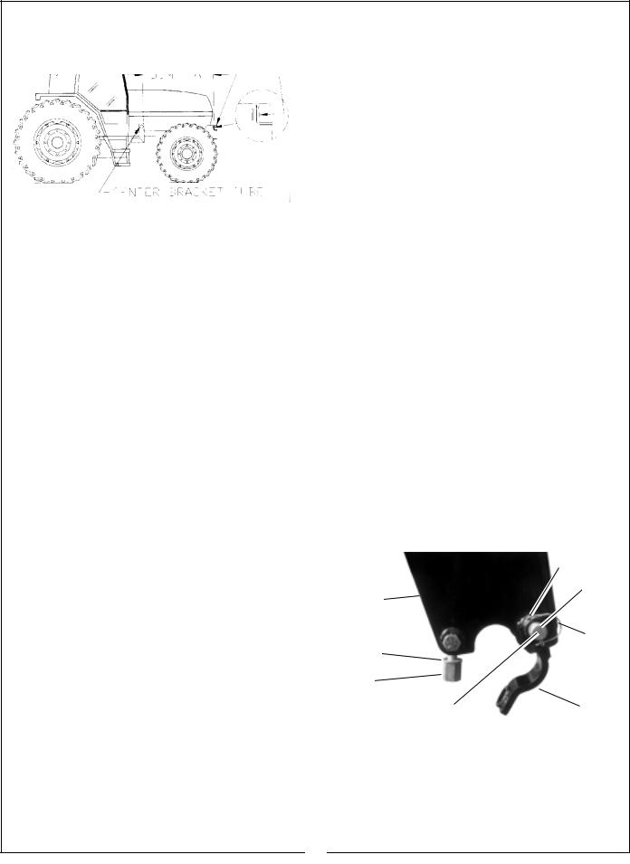
NOTE: Some Models of the 3860 Loader have been designed to custom fit specific makes and models of tractors. These will not require this field change.
Figure 2 |
|
|
|
|
|
|
|
|
|
FORWARD SIDE |
|||
|
|
|
|
|||
|
|
|
|
|
|
|
|
|
|
|
|
|
|
|
|
FRONT BRACKET |
||||
|
|
|
|
|
||
|
|
|
DIM. “A” |
|||
|
|
|
|
|
|
|
CENTER BRACKET TUBE
Figure 3
SUBFRAME ASSEMBLY
ADJUSTABLE TO
CLEAR HEADLIGHTS
FRONT CROSSBRACE
ASSEMBLY
48 15/32
SUBFRAME CROSSTUBE
Figure 4
SUBFRAME ASSEMBLY
ADJUSTABLE TO
CLEAR HEADLIGHTS
FRONT CROSSBRACE
ASSEMBLY
53 15/32
SUBFRAME CROSSTUBE
Quick Draw Latch Attach: Before installing loader to tractor, install quick draw latch attach to loader. Using a hoist, install bucket or attachment to your quick draw latch attach. Refer to Figure 5 and pages 27 & 28 for quick draw latch attach instructions. Following these instructions will add stability to loader package and will allow easier handling of loader with a hoist.
Figure 5
3
5
1
2
4
(1)Top pin 1-1/8” x 6-7/8”, 2 places.
(2)Bottom pin 1-1/8” x 6-7/8”, 2 places
(3)Clevis pin 5/16” x 2”, 4 places
(4)Cotter pin 1/8” x 1”, 4 places
(5)Quick Draw Latch Attach Adapter.
Remove hinge nuts and hardened flatwashers from eyebolts. Swing hinge assemblies back. Reinstall hardened flatwashers and hinge nuts onto eyebolts. Remove snap pins from inner hole of rear hinge pins and reinstall into outer holes of rear hinge pins. Using snap pins as handles, remove rear hinge pins and hinge assemblies from loader. Refer to Figure 6.
Figure 6 |
|
6 |
|
|
|
8
7
3
4
1
5 |
2 |
|
(1)Hinge nut.
(2)Hinge assembly.
(3)Loader mounted snap pin position.
(4)Hardened flatwasher.
(5)Rear hinge pin.
(6)Subframe bushing.
(7)Subframe pedestal.
(8)Rear hinge pin outer hole.
10
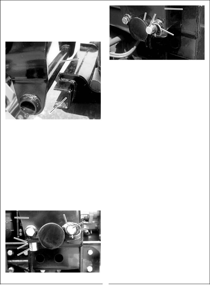
Using a hoist to support the loader frame, align the subframe crosstube with the front bracket. Refer to Figure 7 and Figures 2, 3, & 4, page 10.
 CAUTION
LIFT AND SUPPORT ALL LOADER COMPONENTS SAFELY.
8 |
9 |
7 |
|
|
3
1
Figure 9
(1)Hinge nut.
(2)Hinge assembly.
(3)Snap pin in loader mounted position.
(4)Hardened flatwasher.
(5)Rear hinge pin.
(6)Subframe bushing.
(7)Subframe pedestal.
(8)Center mounting bracket tubes.
(9)Rear hinge pin outer hole.
2 |
TORQUE IDENTIFICATION |
(1) |
Subframe Crosstube. |
Figure 7 |
(2) |
Front Bracket. |
|
|
Slowly drive the tractor forward until the subframe crosstube is seated into the front bracket. Using hoist, lower the front end loader until the subframe assembly is seated on center bracket tubes. Refer to Figures 2, 3, & 4, page 10.
Using snap pins as handles, reinstall rear hinge pins and hinge assemblies. Remove snap pins from outer holes of rear hinge pins and reinstall into inner holes. Secure rear hinge pins to subframe bushings in loader mounted position as shown in Figure 8. Remove hinge nuts and hardened flatwashers from eyebolts. Swing hinge assemblies forward. Secure by locking hinge assemblies into position using hardened flatwashers and hinge nuts. Torque hinge nuts to 200 ft. lb. Refer to Figures 8 & 9.
|
6 |
7 |
5 |
|
|
|
3 |
2 |
|
Torque all mounting kit and loader hardware as specified.
(A)Identify hardware size and grade.
(B)Refer to Torque Chart, page 43 and find correct torque for your hardware size and grade.
(C)Torque hardware to this specification unless otherwise specified.
IMPORTANT: Make sure that all front bracket to tractor hardware and loader subframe to front crossbrace assembly hardware has been torqued properly before operating loader. Refer to Figure 10.
Loader Subframe
Figure 10
Loader Subframe to
Front Crossbrace
Asembly (3 each side)
4 |
|
|
Loader Subframe |
|
|
||
1 |
|
|
|
|
|
|
|
|
|
|
|
Front Crossbrace Assy. |
|
||
|
|
|
|
|
|
|
|
|
|
|
|
|
|
||
|
|
|
|
|
Front Bracket to Tractor Bolts |
||
|
FIGURE 8 |
|
|
|
(Quantity varies with Bracket Design |
||
|
|
|
|
|
|
|
|
|
|
|
|
|
|
|
|
11

3. PRE-OPERATION INSTRUCTIONS
IMPORTANT: Do not extend bucket cylinders without quick draw latch attach installed on loader. Failure to follow these instructions could cause attachment cylinder damage and will void loader warranty.
TRANSMISSION FLUID
Check the tractor hydraulic fluid level and fill, if required.
INITIAL LOADER OPERATION
NOTE: Keep engine speed at low idle during the initial loader operation.
 CAUTION
ESCAPING HYDRAULIC FLUID UNDER PRESSURE CAN HAVE SUFFICIENT FORCE TO PENETRATE SKIN, CAUSING SERIOUS PERSONAL INJURY. BEFORE DISCONNECTING LINES, BE SURE TO RELIEVE ALL PRESSURE.
BEFORE APPLYING PRESSURE TO SYSTEM, BE SURE ALL CONNECTIONS ARE TIGHT AND THAT LINES, TUBES AND HOSES ARE NOT DAMAGED.
FLUID ESCAPING FROM A VERY SMALL HOLE CAN BE ALMOST INVISIBLE. USE A PIECE OF CARDBOARD OR WOOD, RATHER THAN HANDS, TO SEARCH FOR SUSPECTED LEAKS.
IF INJURED BY ESCAPING FLUID, SEE A DOCTOR AT ONCE. SERIOUS INFECTION OR REACTION CAN DEVELOP IF PROPER MEDICAL TREATMENT IS NOT ADMINISTERED IMMEDIATELY. REFER TO FIGURE 1.
2
3
1
Figure 1
(1)Hydraulic line.
(2)Cardboard.
(3)Magnifying glass.
EXTERNAL LOADER AND/OR
TRACTOR VALVE
 CAUTION
WHEN PROPERLY INSTALLED, THE TRACTOR REMOTE VALVE OR EXTERNAL VALVE CONTROL LEVER/LEVERS WILL CONTROL THE LOADER HYDRAULIC CIRCUITS AS SHOWN IN FIGURES 2 AND 3. REFER TO TRACTOR OPERATOR MANUAL FOR FURTHER EXPLANATION OF TRACTOR REMOTE CONTROL LEVER/LEVERS.
IMPORTANT: Contaminants in hydraulic fluid can cause valve spools to stick. BE ALERT when operating loader and follow your tractor Operator Manual hydraulic fluid maintenance schedule.
LOADER MOUNTED CONTROL VALVE EQUIPPED WITH SINGLE LEVER CONTROL HANDLE OR TRACTOR REMOTE VALVE EQUIPPED WITH SINGLE LEVER CONTROL HANDLE
If your loader utilizes a loader mounted control valve equipped with single lever control handle or tractor remote valve equipped with single lever control handle, it will function as described in Figure 2.
Front of Tractor |
|
|
|
|
|
|
|
|
|
Figure 2 |
|
|
|
|
Number 1 Position: |
Pull the joystick back to |
|
|
raise loader. |
|
Number 2 Position: |
Push the joystick forward to |
|
|
lower loader. |
|
Number 3 Position: |
Push the joystick full forward |
|
|
to activate float position. |
|
Number 4 Position: |
Push the joystick outward to |
|
|
dump attachment. |
|
Number 5 Position: |
Pull the joystick inward to |
|
|
roll back attachment. |
|
12
 Loading...