


LCA-2
LCA-2A
LCA-2 PC
LCC-2
POWE |
R |
|
|
||
READY |
||
|
TION |
|
POR |
|
|
RINS |
E |
|
|
||
REFILL |
||
STO |
P! |
|
|
||
|
|
TER |
HOT |
WA |
|
|
|
|
INSTALLATION & OPERATING GUIDE
BUNN-O-MATIC CORPORATION
POST OFFICE BOX 3227
SPRINGFIELD, ILLINOIS 62708-3227
PHONE: (217) 529-6601 FAX: (217) 529-6644
To ensure you have the latest revision of the Operating Manual, or to view the Illustrated Parts Catalog, Programming Manual, or Service Manual, please visit the Bunn-O-Matic website, at www.bunn.com. This is absolutely FREE, and the quickest way to obtain the latest catalog and
manual updates. For Technical Service, contact Bunn-O-Matic Corporation at 1-800-286-6070.
34766.0000S 06/11 ©2002 Bunn-O-Matic Corporation
BUNN-O-MATIC COMMERCIAL PRODUCT WARRANTY
Bunn-O-Matic Corp. (“BUNN”) warrants equipment manufactured by it as follows:
1)All equipment other than as specified below: 2 years parts and 1 year labor.
2)Electronic circuit and/or control boards: parts and labor for 3 years.
3)Compressors on refrigeration equipment: 5 years parts and 1 year labor.
4)Grinding burrs on coffee grinding equipment to grind coffee to meet original factory screen sieve analysis: parts and labor for 3 years or 30,000 pounds of coffee, whichever comes first.
These warranty periods run from the date of installation BUNN warrants that the equipment manufactured by it will be commercially free of defects in material and workmanship existing at the time of manufacture and appearing within the applicable warranty period. This warranty does not apply to any equipment, component or part that was not manufactured by BUNN or that, in BUNN’s judgment, has been affected by misuse, neglect, alteration, improper installation or operation, improper maintenance or repair, damage or casualty. This warranty is conditioned on the Buyer 1) giving BUNN prompt notice of any claim to be made under this warranty by telephone at (217) 529-6601 or by writing to Post Office Box 3227, Springfield, Illinois 62708-3227; 2) if requested by BUNN, shipping the defective equipment prepaid to an authorized BUNN service location; and 3) receiving prior authorization from BUNN that the defective equipment is under warranty.
THE FOREGOING WARRANTY IS EXCLUSIVE AND IS IN LIEU OF ANY OTHER WARRANTY, WRITTEN OR ORAL, EXPRESS OR IMPLIED, INCLUDING, BUT NOT LIMITED TO, ANY IMPLIED WARRANTY OF EITHER MERCHANTABILITY OR FITNESS FOR A PARTICULAR PURPOSE. The agents, dealers or employees of BUNN are not authorized to make modifications to this warranty or to make additional warranties that are binding on BUNN. Accordingly, statements by such individuals, whether oral or written, do not constitute warranties and should not be relied upon.
If BUNN determines in its sole discretion that the equipment does not conform to the warranty, BUNN, at its exclusive option while the equipment is under warranty, shall either 1) provide at no charge replacement parts and/or labor (during the applicable parts and labor warranty periods specified above) to repair the defective components, provided that this repair is done by a BUNN Authorized Service Representative; or 2) shall replace the equipment or refund the purchase price for the equipment.
THE BUYER’S REMEDY AGAINST BUNN FOR THE BREACH OF ANY OBLIGATION ARISING OUT OF THE SALE OF THIS EQUIPMENT, WHETHER DERIVED FROM WARRANTY OR OTHERWISE, SHALL BE LIMITED, AT BUNN’S SOLE OPTION AS SPECIFIED HEREIN, TO REPAIR, REPLACEMENT OR REFUND.
In no event shall BUNN be liable for any other damage or loss, including, but not limited to, lost profits, lost sales, loss of use of equipment, claims of Buyer’s customers, cost of capital, cost of down time, cost of substitute equipment, facilities or services, or any other special, incidental or consequential damages.
392, AutoPOD, AXIOM, BrewLOGIC, BrewMETER, Brew Better Not Bitter, BrewWISE, BrewWIZARD, BUNN Espress, BUNN Family Gourmet, BUNN Gourmet, BUNN Pour-O-Matic, BUNN, BUNN with the stylized red line, BUNNlink, Bunn-OMatic, Bunn-O-Matic, BUNNserve, BUNNSERVE with the stylized wrench design, Cool Froth, DBC, Dr. Brew stylized Dr. design, Dual, Easy Pour, EasyClear, EasyGard, FlavorGard, Gourmet Ice, Gourmet Juice, High Intensity, iMIX, Infusion Series, Intellisteam, My Café, PowerLogic, Quality Beverage Equipment Worldwide, Respect Earth, Respect Earth with the stylized leaf and coffee cherry design, Safety-Fresh, savemycoffee.com, Scale-Pro, Silver Series, Single, Smart Funnel, Smart Hopper, SmartWAVE, Soft Heat, SplashGard, The Mark of Quality in Beverage Equipment Worldwide, ThermoFresh, Titan, A Partner You Can Count On, Air Brew, Air Infusion, Beverage Bar Creator, Beverage Profit Calculator, Brew better, not bitter., BUNNSource, Coffee At Its Best, Cyclonic Heating System, Digital Brewer Control, Nothing Brews Like a BUNN, Pouring Profits, Signature Series, Tea At Its Best, Phase Brew, The Horizontal Red Line, trifecta, Ultra, Velocity Brew are either trademarks or registered trademarks of Bunn-O-Matic Corporation.
2 |
34766 050511 |
|
CONTENTS
Warranty........................................................................... |
2 |
Introduction...................................................................... |
3 |
User Notices..................................................................... |
4 |
Electrical Requirements.................................................... |
5 |
CE Requirements.............................................................. |
5 |
Plumbing Requirements................................................... |
6 |
Initial Set-up..................................................................... |
6 |
Electrical Hook-up............................................................ |
6 |
Plumbing Hook-up........................................................... |
6 |
Setting Dispenser Flow Rate............................................. |
7 |
Selecting the Correct Pump Tubing.................................. |
8 |
Operating Controls & Interface......................................... |
9 |
Initial Fill & Heat............................................................. |
10 |
FlavorGard™ Feature....................................................... |
11 |
Rinse Alarm Feature....................................................... |
11 |
BIB Empty Lockout Feature............................................ |
12 |
Brew Temperature Lockout Feature................................ |
12 |
Programming the Dispenser Flow Rate.......................... |
13 |
Loading the Concentrate................................................. |
19 |
Priming the Concentrate Lines....................................... |
19 |
Operating the Pull & Hold Dispenser.............................. |
20 |
Operating the Preset Portion Control Dispenser............. |
21 |
Filling Cambros or other large containers....................... |
21 |
Cleaning & Preventive Maintenance................................ |
22 |
Replacing the Pump Tubing............................................ |
23 |
Draining the Hot Water................................................... |
24 |
Troubleshooting.............................................................. |
25 |
Field Calibration of the Concentrate Pumps.................... |
30 |
Dispenser Flow Rate Calibration..................................... |
31 |
Field Calibrating the Hot Water Flow Rate....................... |
31 |
Field Calibrating the Empty BIB Warning........................ |
32 |
Schematic Wiring Diagrams........................................... |
33 |
INTRODUCTION
The Liquid Coffee Ambient Dispenser (LCA-2) and the Liquid Coffee Chilled Dispenser (LCC-2) delivers two types of coffee made from liquid concentrate plus hot water. The dispenser can be set up for continuous draw (by the cup) for self-serve applications, or portion-control to fill carafes and decanters for wait staff. Follow the Concentrate Manufacturer’s Storage and Shelf Life recommendations. Product Flavor Profile is extended with chilled product storage cabinet featured in the LCC-2.
This dispenser is designed to operate when ambient temperatures are from 32°F (0°C) minimum to 104°F (40°C) maximum.
3 |
34766 030508 |
|
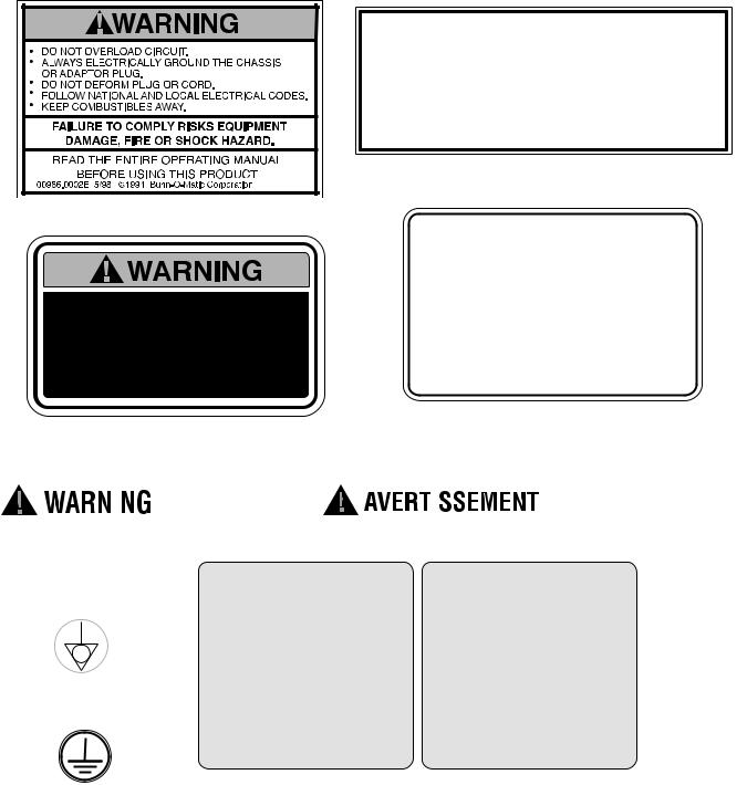
USER NOTICES
Carefully read and follow all notices on the equipment and in this manual. They were written for your protection. All notices are to be kept in good condition. Replace any unreadable or damaged labels.
00986.0002
To reduce the risk of electric shock, do not remove or open cover.
No user-serviceable parts inside. Authorized service personnel only. Disconnect power before servicing.
As directed in the International Plumbing Code of the International Code Council and the Food Code Manual of the Food and Drug Administration (FDA), this equipment must be installed with adequate backflow prevention to comply with federal, state and local codes. For models installed outside the U.S.A., you must comply with the applicable Plumbing /Sanitation Code for your area.
00656.0001
Optional Field Wiring
208-240 V, 25.8 A, 6200 W 1PH, 2-Wire + GND, 60HZ or
120/208-240 V, 25.8 A, 6200 W 1PH, 3-Wire + GND, 60HZ
37881.0000 |
28181.0003 |
|
|
|
|
|
|
|
|
|
|
|
|
|
|
|
|
|
|
|
|
|
|
|
|
11646.0002 |
|
|
||
|
|
REMINDER! |
AIR FILTER |
|||
|
|
CLEAN AIR FILTER |
CLEAN WEEKLY! |
|||
|
|
WEEKLY |
(LOCATED UNDER THE DISPENSER) |
|||
|
|
(LOCATED UNDER THE DISPENSER) |
FILTRO DE AIRE |
|||
|
|
RECORDATORIO! |
||||
00824.0001 |
LIMPIAR |
|||||
LIMPIAR EL FILTRO DE |
SEMANALMENTE! |
|||||
|
|
|||||
|
|
AIRE SEMANALMENTE |
(LOCALIZADO DEBAJO |
|||
(LOCALIZADO DEBAJO |
DEL DISPENSADOR) |
|
|
DEL DISPENSADOR) |
|
|
40054.0000 |
00824.0002 |
|
4 |
34766 012711 |
|
ELECTRICAL REQUIREMENTS
CAUTION: The dispenser must be disconnected from the power source until specified in Electrical Hook-Up.
The LCA-2 and LCC-2 dispensers are supplied with a 120-volt / 15 Amp cord set and require a 2-wire, grounded, individual branch circuit rated for 120 volts AC, 15 amp, single phase, 60Hz. The mating connector must be a NEMA 5-15R.
The LCA-2C and LCC-2C dispensers are supplied with a 120-volt / 20 Amp cord set and require a 2-wire, grounded, individual branch circuit rated for 120 volts AC, 20 amp, single phase, 60Hz. The mating connector must be a NEMA 5-20R.
These dispensers can be Field Wired for 208 or 240 volt applications. This requires a 2 or 3-wire, grounded, individual branch circuit rated for 208/240 volts AC, 30 amp, single phase, 60 Hz.
NOTE: The internal terminal block must be rewired for 208/240 applications, (see Optional Field Wiring
Diagram).
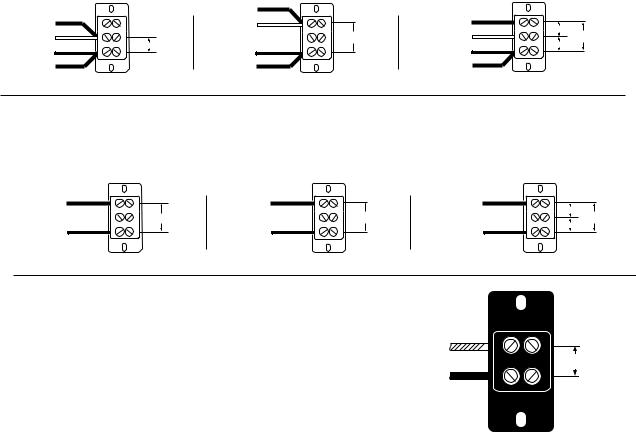
FIELD WIRING TERMINAL BLOCK DIAGRAM Models without Master ON/OFF Switch
|
|
HEATER RED |
|
|
|
HEATER RED |
|
10A. FUSE - WHITE |
|
HEATER RED |
|
|
|
|
|
|
|
10A. FUSE - WHITE |
|
|
208 or |
10A. FUSE - WHITE |
120V A.C. 208 or |
|
120V A.C. |
|
240V A.C. |
|
240V A.C. |
10A. FUSE - BLACK |
10A. FUSE - BLACK |
|
10A. FUSE - BLACK |
120V A.C. |
|
|
|
|
|||
LIMIT SW. - BLACK |
Fig. 1 |
LIMIT SW. - BLACK |
Fig. 2 |
LIMIT SW. - BLACK |
Fig. 3 |
For all 208 - 240 Volt Connections: Use No. 10 AWG Wires suitable for 90°C (194°F)
1.Unit shipped per Fig. 1, wired for 120V A.C./2-Wire.
2.For 208 - 240V A.C./2-Wire per Fig. 2: Move both the Red-Heater wire and the White-Fuse wire to the Top Red Terminal as shown.
3.For 120/208 - 240V A.C./3-Wire per Fig. 3: Move the Red Heater wire to the Top Red Terminal as shown.
FIELD WIRING TERMINAL BLOCK DIAGRAM
Models with Master ON/OFF Switch
RED |
|
RED |
|
RED |
|
|
TO MASTER |
120V A.C. |
TO MASTER |
208 or |
TO MASTER |
120V A.C. |
208 or |
ON/OFF |
ON/OFF |
ON/OFF |
|
|||
240V A.C. |
240V A.C. |
|||||
SWITCH |
|
SWITCH |
|
SWITCH |
120V A.C. |
|
BLACK |
Fig. 1 |
BLACK |
Fig. 2 |
BLACK |
Fig. 3 |
|
|
|
|
|
|||
For all 208 - 240 Volt Connections: Use No. 10 AWG Wires suitable for 90°C (194°F)
1.Unit shipped per Fig. 1, wired for 120V A.C./2-Wire.
2.For 208 - 240V A.C./2-Wire per Fig. 2.
3.For 120/208 - 240V A.C./3-Wire per Fig. 3.
The LCR-2A dispenser is internally wired from the factory for 230 Volts AC Single Phase 50/60 Hz. It requires a 2-wire, grounded, individual branch circuit rated for 230 Volts AC.
L2 RED
230V, 230A.Cor.
L1 BLACK
240V A.C.
CE REQUIREMENTS
•This appliance must be installed in locations where it can be overseen by trained personnel.
•For proper operation, this appliance must be installed where the temperature is between 5°C to 35°C.
•Appliance shall not be tilted more than 10° for safe operation.
•An electrician must provide electrical service as specified in conformance with all local and national codes.
•This appliance must not be cleaned by water jet.
•This appliance is not intended for use by persons (including children) with reduced physical, sensory or mental capabilities, or lack of experience and knowledge, unless they have been given instructions concerning use of this appliance by a person responsible for its safety.
•Children should be supervised to ensure they do not play with the appliance.
• If the power cord is ever damaged, it must be replaced by the manufacturer or authorized service personnel with a special cord available from the manufacturer or its authorized service personnel in order to avoid a hazard.
• Machine must not be immersed for cleaning.
5 |
34766 062210 |
|
PLUMBING REQUIREMENTS
The dispenser may be connected to a cold or hot water system (140°F Max.) with operating pressure between 20 and 90 psi (138 and 620 kPa) from a 1/2” or larger supply line. A shut-off valve should be installed in the line before the dispenser. Install a regulator in the line when pressure is greater than 90 psi (620 kPa) to reduce it to 50 psi (345 kPa). The water inlet fitting is 3/8” flare. Dispensers set up to deliver to 1.8 Oz./sec. (53.2 ml/sec) per dispense tip, require a water supply source that can deliver a minimum of 1.7 gpm (6.4 lpm) at the inlet fitting. Dispensers set up to deliver 2.6 Oz./sec. (76.9 lpm) per dispense tip, require a water supply source that can deliver a minimum of 2.4 gpm (9.2 lpm) at the inlet fitting.
NOTE: Bunn-O-Matic recommends 3/8” tubing from the 1/2” water supply line. At least 18 inches of FDA approved flexible beverage tubing, such as reinforced braided polyethylene or silicone, before the dispenser will facilitate movement to clean the counter top. Bunn-O-Matic does not recommend the use of a saddle valve to install the dispenser. The size and shape of the hole made in the supply line by this type of device may restrict water flow.
As directed in the International Plumbing Code of the International Code Council and the Food Code Manual of the Food and Drug Administration (FDA), this equipment must be installed with adequate backflow prevention to comply with federal, state and local codes. For models installed outside the U.S.A., you must comply with the applicable Plumbing /Sanitation Code for your area.
INITIAL SET-UP
NOTE: The LCC-2 (Chilled Unit) weighs approximately 80 lbs. (36.3 kg) and the LCA-2 (Ambient Unit) weighs approximately 70 lbs. (31.8 kg). If necessary, use more than one person when lifting or moving the dispenser.
1.Locate and remove the information packets and tube kits from top of packaging and set aside.
2.Remove foam packing and cut around the bottom of box.
3.Remove the box and the rest of the foam packing.
4.Open the dispenser door and remove the drip tray and the lower splash guard panel.
5.Set dispenser on the counter where it is to be used. CAUTION: DO NOT LIFT ON THE DOOR.
6.Confirm the dispenser is level on the counter.
ELECTRICAL HOOK-UP
CAUTION: Improper electrical installation will damage electronic components.
1.An electrician must provide electrical service as specified in conformance with all local, state and federal electrical codes.
2.Using a voltmeter, check the voltage and color-coding of each conductor at the electrical source.
3.Connect the dispenser to the power source.
4.If plumbing is to be hooked up later, be sure the dispenser is disconnected from the power source. If plumbing has been hooked up, the dispenser is ready for Initial Fill & Heat.
PLUMBING HOOK-UP
1.Flush the water line to remove any debris or foreign material.
2.Securely attach the water line to the 3/8” flare fitting, on bottom right side of the dispenser.
3.Turn on the water supply and check for leaks.
NOTE: Water pipe connections and fixtures directly connected to a potable water supply shall be sized, installed, and maintained in accordance with federal, state, and local codes.
6 |
34766 062210 |
|
SETTING DISPENSER FLOW RATE
The dispenser comes from the factory with flow restrictors in the mix chambers. With the restrictors in place the dispense rate is about 1.8 oz./sec (53.2 ml/sec) and is used primarily for cup at a time dispensing. The flow restrictors can be removed to increase the dispense rate to about 2.5 oz./sec (74 ml/sec) for larger volume dispensing (airpots, carafes, etc.).
NOTE: The hot water FlowRate is fixed at approximately 1.7 oz/sec. and can not be adjusted.
Removing the restrictors:
1.Disconnect the dispenser from the AC power source.
2.Open the Product Cabinet door.
3.Remove the concentrate tube, vent line and grommet from mix chamber ports in side the product cabinet.
4.Remove the two screws that fasten mix chamber to the control panel.
5.Gently pull mix chamber away from dispenser to expose water line connection, (you may have to rotate it slightly).
6.Disconnect FlavorGard™ sensor wire and hot water tubing from the mix chamber.
7.Remove the flow restrictor from the inlet to the mix chamber.
8.Reconnect FlavorGard™ sensor wire and hot water tubing to the mix chamber.
9.Place mix chamber back into position in the dispenser, (you may have to rotate it slightly) and secure it with the two screws
10.Reposition the grommet, vent line and pump tubing onto the mix chamber ports.
Caution: Failure to properly replace and secure any of the above components may result leaks and/or cause damage to the dispenser.
If you changed the Dispenser Flow Rate, you will need to reprogram the dispenser to the new rate, seeProgramming the Dispenser.
CAUTION: Failure to reprogram the Dispenser Flow Rates will result in inaccurate Mix Ratios.
Reprogramming the Dispenser Flow Rate:
1.Remove the lower splash guard panel and locate the Programming module.
2.Use the Down Arrow key to enter into the programming function and scroll through the menu’s to the “CAL LEFT SIDE?” menu and select “YES”.
3.Scroll down to the “CAL LF WTR VOL” menu
4.Use the (+) & (-) keys to enter a volume of 50 Oz. (1478 mL). This will recalibrate the Left dispenser to the new rate.
5.Scroll down to the “CAL RT WTR VOL” menu
6.Use the (+) & (-) keys to enter a volume of 50 Oz. (1478 mL). This will recalibrate the Right dispenser to the new rate.
7.Select “Exit” to leave the programming menu.
Note: The default volume of 50 Oz (1478 mL), is the typical Cal Volume for a 2.5 Oz/sec Flow Rate Test, see Field Calibration of the Concentrate Pumps / Dispenser Flow Rates.
7 |
34766 073007 |
|
SELECTING THE CORRECT PUMP TUBING
There are two pump tube sizes available for use with this dispenser. To determine the correct tubing for you application, first determine the dispenser flow rate you intend to use, refer to Setting Dispenser Flow Rate. Then look up the recommended tube size for the mix ratio of your concentrate, refer to the Tube Selection Chart.
|
|
|
|
|
|
TUBE SELECTION CHART |
|
|
|
|
|
|
|
|
|
||||
|
Dispense |
Concentrate Ratios |
|
|
|
|
|
|
|
|
|
|
|
|
|
|
|||
|
Rate |
25 |
30 |
35 |
40 |
45 |
50 |
55 |
60 |
65 |
70 |
75 |
|
80 |
85 |
90 |
|
95 |
100 |
|
1.8 Oz/sec. |
3/16” I.D. TUBING |
|
|
|
|
1/8” I.D. TUBING |
|
|
|
|
|
|||||||
|
(53 ml/sec.) |
|
|
|
|
|
|
|
|
|
|
|
|
|
|
|
|
|
|
|
2.5 Oz/sec. |
3/16” I.D. TUBING |
|
|
|
|
|
|
|
1/8” I.D. TUBING |
|
|
|||||||
|
(74 ml/sec.) |
|
|
|
|
|
|
|
|
|
|
|
|
|
|
|
|
|
|
|
|
|
|
|
|
|
|
|
|
|
|
|
|
|
|
|
|
|
|
Examples: |
|
|
|
|
|
|
|
|
|
|
|
|
|
|
|
|
|
|
|
1.For a Dispenser Flow Rate of 2.5 Oz./sec (74 mL/sec) and a Mix Ratio of 35:1 – use 3/16” I.D. Tubing.
2.For a Dispenser Flow Rate of 1.8 Oz./sec (53 mL/sec) and a Mix Ratio of 60:1 – use 1/8” I.D. Tubing.
Tube kits can be purchased from BUNN-O-MATIC.
Part # 34727.1000 for 3/16” I.D. Tubing or #34728.1000 for 1/8” I.D. Tubing.
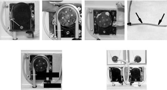
INSTALLING THE PUMP TUBING (Refer to the Tubing Installation Instructions in side the cabinet door for details.)
1.Loosen the thumbscrew securing the tubing retainer plate to the pump housing. Set it and the retainer plate aside.
2.Depress the tension screw and remove it from the notch in the pump body, releasing the spring tension on the pump band.
3.Apply lubricant (BUNN-O-MATIC part number M2531.0001) to the new pump tubing.
4.Insert the tubing onto the mix chamber port and wrap the tubing around the pump rotor, making sure that the elbow and clamps end up on the bottom side of the pump body.
5.Close the compression band reinsert the tension screw into the notch in the pump housing.
6.Replace the tubing retainer plate and tighten the thumbscrew.
7.Reconnect bag connector to the product box.
8.Repeat steps 1 through 7 for the other pump.
9.Prime the pumps. Refer to Priming the Concentrate Lines section.
Thumbscrew |
|
|
|
|
|
|
|
|
|
|
|
|
|
Tension |
|
|
|
|
2.0” |
|
|
|
|
|
2.0” |
|
|
|
|
|
|
|
|
|
|
|
|
|
|
|
|
Screw |
|
Lubricate between arrows |
|||||||||||
|
|
||||||||||||
Remove Retaining Plate Release Spring Tension |
Remove Tubing |
|
|
Lubricate New Tube |
|||||||||
Tension Screw |
|
Tube Clamp |
|
Install New Tubing |
Completed Installation |
8 |
34766 112502 |
|
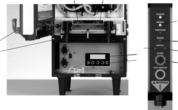
OPERATING CONTROLS AND INTERFACE
1a. Dispense Handles: Pull and Hold to dispense product.
1b. Dispense Switches: Push and Release to dispense product for Portion Control Models. 2. Stop Switch: Momentary switch stops all dispense functions.
3a. Hot Water Switch: Push and Hold switch to dispense hot water from the center dispense tip. 3b. Push and Release switch for Portion Control Models.
4.Alternate Portion Control Switch: Momentarily pushed to select the Alternate Portion Control Volume #2.
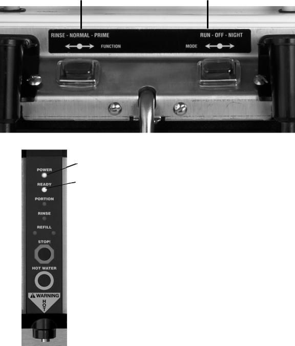
5.Function Selector Switch: Allows the user to set the dispenser into different dispensing modes.
a.Rinse: Dispenses hot water onlyFlushes the mix chamber and dispense tip.
b.Prime: Dispenses concentrates only – Primes the concentrate pump.
c.Normal: Normal dispense mode - Dispenses mixed product (concentrate and water).
6.Mode Selector Switch: Allows the user to set the dispenser into different operating modes.
a.Run: Normal operating position.
b.Off: Turns off all functions including tank heater and chiller.
WARNING - The OFF Mode does not remove AC power from the dispenser. Disconnect power source before servicing the dispenser
c.Night: Anti-pilfering mode that disables dispensing, but keeps the tank heater and chiller (if applicable) operational.
7.Door Interlock Switch: Unit will not dispense product if the door is open.
8.Power LED: Red - illuminates when AC power is applied to dispenser.
9.Ready LED: Green - illuminates when the water is at the preset ready temperature.
10.Portion LED: Yellow - illuminates when the portion dispense option has been selected, (5 second delay).
11.Rinse LED: Yellow - illuminates when the optional preset rinse alarm time has elapsed.
12.Left Refill LED: Yellow - illuminates when the Left Concentrate BIB needs replaced.
13.Right Refill LED: Yellow - illuminates when the Right Concentrate BIB needs replaced.
14.Programming Keypad: Used in conjunction with the LCD display to program and calibrate the dispenser to customer specific requirements. (Located behind the splash guard panel)
15.LCD Display: Displays programming menus and fault messages. (Located behind the splash guard panel)
5 |
6 |
1
4
BUNN ICED COFFEE
AMBIENT UNIT
8
7 

 9
9
 10
10
11
12
15 13  14
14
2
 3
3
9 |
34766 120105 |
|
INITIAL FILL & HEAT
1.Select Normal on the Function Selector Switch and Run on the Mode Selector Switch.
2.Confirm the water supply is on.
3.Connect the dispenser to the power source. The Red POWER LED will illuminate and water will begin flowing into the tank. The dispenser will automatically stop filling when the tank is full. The dispenser will not begin heating the water until after the tank is filled. Dispenser models with product chillers will begin to cool the cabinet at this time.
4.The Green READY LED will illuminate when the tank temperature reaches the preset ready temperature. Note: The time required to heat the water initially will vary depending on the AC Power supplied to the dispenser.
While the tank is heating, the dispenser may be readied for use as described in Programming Functions & Basic
Operations. |
1 |
1 |
3
4
10 |
34766 112502 |
|
FlavorGard™ Feature
FlavorGard™ is a patented feed back control loop that monitors the mixed product and adjusts the concentrate delivery rate to maintain a consistent mix profile, i.e. Flavor Profile. The system consists of a conductance probe mounted in the final stages of the mixing chamber, a metering pump with RPM sensor and a digital controller. Once you have completed the installation of the dispenser, entered the desired mix ratio for your concentrate, dispensed several cups of the mixed product, and are satisfied with the Flavor and Strength being delivered, simply enable FlavorGard™, (refer to FlavorGard™ in Programming the Dispenser).
The dispenser will automatically calibrate the system to all the factors that make up your particular mix profile, (e.g. water source, filtration system, Brand of concentrate and mix ratio selected, etc.).
NOTE: It is very important that you have dispensed enough product to insure that the dispenser is fully functional and you are satisfied with the Flavor Profile of the mix product before enabling FlavorGard™.
Once FlavorGard™ is enabled, the dispenser will continuously monitor the mix product as it is being dispensed and adjust the metering pump speed to maintain a consistent mixed product, thus eliminating factors such as (settling of the concentrate, tube wear, viscosity changes, liming, etc.).
The system is designed to work with in the range of variations that can be caused by these factors. The factory preset range is (+/- 10 %) and is adjustable to a Max of (+/- 15%). This insures that the FlavorGard™ system is not responding to factors that cannot be corrected by minor adjustments to the speed of the metering pump, (e.g. kinked hoses, low water pressure, severely worn tubes, empty BIB’s, etc).
NOTE: Changes to Concentrate Ratios or Dispenser Flow Rates will automatically disable FlavorGard™. You will need to re-enable FlavorGard™, once you are satisfied with the new Flavor Profile.
Rinse Alarm Feature
Periodic rinsing of the mix chambers and dispense tips is essential for proper maintenance and optimum performance of the dispenser. The automated Rinse Alarm feature has three levels of operation, Disabled, Warning Only and Warning with Brew Lockout, see chart for details.
Alarm Mode
None
Rinse LED will come on 4 hrs prior to the selected time interval and remain on until the Rinse procedure has been performed. The dispenser will continue to serve product.
Rinse LED will come on 4 hrs prior to the selected time interval and remain on until the Rinse procedure has been performed. The dispenser will Lockout and not continue to serve product once the selected time interval has elapsed.
NOTE: The time interval between Rinses is adjustable from 8 to 24 hrs.
The dispenser is shipped with the automated Rinse Alarm disabled, (No Alarm). It is up to the user to determine the Rinse time interval and the level of warning required, based on their application and maintenance procedures. To enable the automated Rinse Alarm feature, refer to RINSE ALARM ? in Programming the Dispenser.
11 |
34766 050103 |
|
 Loading...