


 Loading...
BES-961BC
BES-1261BC
INSTRUCTION MANUAL
Please read this manual before using the machine.
Please keep this manual within easy reach for quick reference.
NINE NEEDLE SIX HEAD ELECTRONIC EMBROIDERY MACHINE
TWELVE NEEDLE SIX HEAD ELECTRONIC EMBROIDERY MACHINE

Precautions
•Unauthorized commercial or industrial use of trademarks or copyrighted materials (such as paintings, drawings, photos, logos, etc.) owned by other companies or persons is illegal. The use of such materials without the permission of their owners may result in criminal or civil liability.
•This manual may be subsequently modified without prior notice.
•Brother Industries, Ltd. shall assume no responsibility for any consequences of using this manual.
Thank you very much for buying a BROTHER sewing machine. Before using your new machine, please read the safety instructions below and the explanations given in the instruction manual.
With industrial sewing machines, it is normal to carry out work while positioned directly in front of moving parts such as the needle and thread take-up lever, and consequently there is always a danger of injury that can be caused by these parts. Follow the instructions from training personnel and instructors regarding safe and correct operation before operating the machine so that you will know how to use it correctly.
SAFETY INSTRUCTIONS
1Safety indications and their meanings
This instruction manual and the indications and symbols that are used on the machine itself are provided in order to ensure safe operation of this machine and to prevent accidents and injury to yourself or other people. The meanings of these indications and symbols are given below.
Indications
The instructions which follow this term indicate situations where DANGER failure to follow the instructions will almost certainly result in death
or severe injury.
The instructions which follow this term indicate situations where CAUTION failure to follow the instructions could cause injury when using the
machine or physical damage to equipment and surroundings.
Symbols
 ................. This symbol (
  ) indicates something that you should be careful of. The picture inside the triangle indicates the nature of the caution that must be taken. (For example, the symbol at left means "beware of injury".)
|
................. This symbol ( |
) indicates something that you must not do. |
|
................. This symbol ( |
) indicates something that you must do. |
|
|
|
The picture inside the circle indicates the nature of the thing that must be done. (For example, the symbol at left means "you must make the ground connection".)
BES-961BC • BES-1261BC |
1 |
2 Notes on safety
 DANGER
Wait at least 5 minutes after turning off the power switch and disconnecting the power cord from the wall outlet before opening the face plate of the control box. Touching areas where high voltages are present can result in severe injury.
 CAUTION
Installation
Machine installation should only be carried out by a qualified technician.
Contact your Brother dealer or a qualified electrician for any electrical work that may need to be done.
The sewing machine weighs more than 720 kg. The installation should be carried out by four or more people.
Do not connect the power cord until installation is complete, otherwise the machine may operate if the start switch is pressed by mistake, which could result in injury.
Be sure to connect the ground. If the ground connection is not secure, you run the risk of receiving a serious electric shock.
When securing the cords, do not bend the cords excessively or fasten them too hard with staples, otherwise there is the danger that fire or electric shocks could occur.
Be sure to wear protective goggles and gloves when handling the lubricating oil or grease, so that no oil or grease gets into your eyes or onto your skin, otherwise inflammation can result.
Furthermore, do not drink the oil or grease under any circumstances, as they can cause vomiting and diarrhoea.
Keep the oil out of the reach of children.
Avoid setting up the sewing machine near sources of strong electrical noise such as highfrequency welding equipment.
If this precaution is not taken, incorrect machine operation may result.
The casters should be secured in such a way so that they cannot move.
Sewing
This sewing machine should only be used by operators who have received the necessary training in safe use beforehand.
The sewing machine should not be used for any applications other than sewing.
Turn off the power switch at the following times, otherwise the machine may operate if the start switch is pressed by mistake, which could result in injury.
•When threading the needle
•When replacing the bobbin and needle
•When not using the machine and when leaving the machine unattended
Do not get on the table.
Table may be damaged.
Attach all safety devices before using the sewing machine. If the machine is used without these devices attached, injury may result.
Do not touch any of the moving parts or press any objects against the machine while sewing, as this may result in personal injury or damage to the machine.
Do not touch the pulse motor and sewing machine bed section during operation or for 30 minutes after operation. Otherwise burns may result.
If an error occurs in machine operation, or if abnormal noises or smells are noticed, immediately turn off the power switch. Then contact your nearest Brother dealer or a qualified technician.
If the machine develops a problem, contact your nearest Brother dealer or a qualified technician.
2 |
BES-961BC • BES-1261BC |
 CAUTION
Cleaning
Turn off the power switch before starting any cleaning work, otherwise the machine may operate if the start switch is pressed by mistake, which could result in injury.
Be sure to wear protective goggles and gloves when handling the lubricating oil or grease, so that no oil or grease gets into your eyes or onto your skin, otherwise inflammation can result.
Furthermore, do not drink the oil or grease under any circumstances, as they can cause vomiting and diarrhoea.
Keep the oil out of the reach of children.
Maintenance and inspection
Maintenance and inspection of the sewing machine should only be carried out by a qualified technician.
Ask your Brother dealer or a qualified electrician to carry out any maintenance and inspection of the electrical system.
Turn off the power switch and disconnect the power cord from the wall outlet at the following times, otherwise the machine may operate if the treadle is depressed by mistake, which could result in injury.
•When carrying out inspection, adjustment and maintenance
•When replacing consumable parts such as the rotary hook and knife.
If the power switch needs to be left on when carrying out some adjustment, be extremely careful to observe all safety precautions.
Use only the proper replacement parts as specified by Brother.
If any safety devices have been removed, be absolutely sure to re-install them to their original positions and check that they operate correctly before using the machine.
Any problems in machine operation which result from unauthorized modifications to the machine will not be covered by the warranty.
BES-961BC • BES-1261BC |
3 |
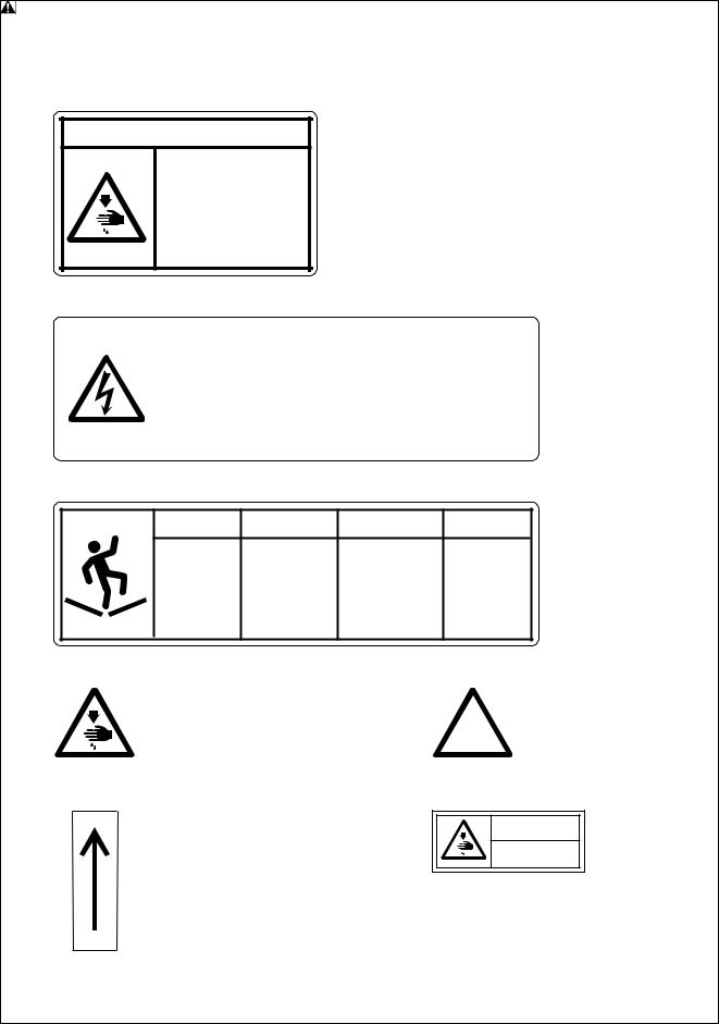
3Warning labels
*The following warning labels appear on the sewing machine.
Please follow the instructions on the labels at all times when using the machine. If the labels have been removed or are difficult to read, please contact your nearest Brother dealer.
1 |
Safety devices: Finger guard, Belt cover, etc. |
 CAUTION
Moving parts may cause injury.
Operate with safety devices. turn off main switch before changing needle, cleaning etc.
2 |
|
|
|
|
|
|
DANGER |
GEFAHR |
DANGER |
PELIGRO |
|
|
|
||||
|
|
|
|
|
|
|
|
Hazardous voltage |
Hochspannung |
Un voltage non adapté |
Un voltaje inadecuado |
|
|
will cause injury, |
verletzungsgefahr! |
provoque des blessures. |
puede provocar las |
|
|
|
|
|
heridas. |
|
|
Turn off main |
Vor Öffnen des |
Pour ouvrir cette plaque, |
|
|
|
switch and unplug |
Gehäuses |
couper le contact |
Antes de abrir esta |
|
|
power cord before |
Hauptschalter |
general de la machine |
tapa, desconecte la |
|
|
opening this cover. |
ausschalten und |
et debrancher le cable |
máquina y |
|
|
|
Netzstecker ziehen! |
d’alimentation. |
desenchufela de la red. |
|
|
|
|
|
|
3 |
ACHTUNG |
ATTENTION |
ATENCION |
CAUTION |
|||
Table may |
Der Tisch kann |
Vous risquez |
La mesa se |
be damaged. beschädigt |
d’endommager |
puede dañar. |
|
|
werden. |
la table. |
|
Do not get on |
Nicht auf den |
No montez pas |
No pise la |
the table. |
Tisch stehen. |
sur la table. |
mesa. |
4
6
Never touch or push the thread take up during operation as it may result in injuries machine.
Direction of operation
5 Never touch or push the  needle bar during operation
  as it may result in injuries or
  damage to the sewing machine.
7 |
|
|
|
|
CAUTION |
Do not touch this part during activitation or for 30 minutes after shut-off. Otherwise burns may result.
4 |
BES-961BC • BES-1261BC |
6 |
4 |
|
3 |
||
Finger guard |
Belt cover
7
5
3
2 |
■BES-961BC |
|
7
1
1 |
2 |
BES-961BC • BES-1261BC |
5 |
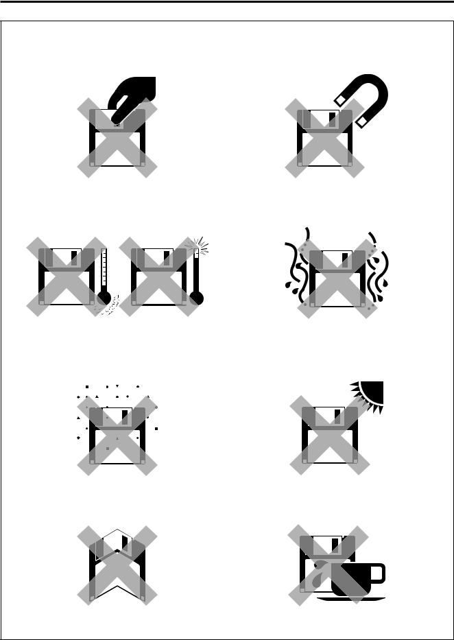
Before Starting Operation
Do not force open the shutter for direct contact with the magnetic area.
Do not store floppy disks in an extremely high or low ambient temperature.
Do not use or store floppy disks in a dusty place.
Do not bend the disk. Do not put things on the disk.
Do not bring disks near magnetic matters such as magnetic screwdriver.
Do not use floppy disks under high humidity.
Do not store floppy disks under direct sunlight.
Avoid contact with solvent or drink.
Do not remove the disk out of the drive during the access lamp is lit.
6 |
BES-961BC • BES-1261BC |
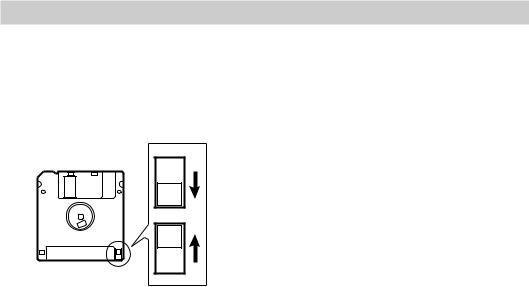
Protecting data in floppy disks
Write-protection is available for a floppy disk to prevent undesired data deletion. A write-protected disk is read-only. It is recommended to provide write-protection for disks which contain important data.
To do so, slide the write-protect notch to open the slot as shown below.
Slide the notch in this direction to prevent data loss or overwriting.
Slide the notch in this direction to write data.
BES-961BC • BES-1261BC |
7 |

Procedure of Reading This Manual
Explanation of models
This manual explains two models:
-BES-961BC (9 needles)
-BES-1261BC (12 needles)
Explanation for individual model is provided by identifying the model name. Check the model before using the machine. The display is BES-961BC.
Configuration of this manual
This manual consists of the following chapters:
Chapter 1 Preparation of Embroidery Machine
This Chapter describes the specifications, installation and preparatory procedures of starting up the machine.
Chapter 2 Embroidering Procedures
Provides explanations on the operation panel and briefly reviews the flow of embroidering processes.
Chapter 3 Selection of Data and Embroidering
This Chapter describes procedures of reading sewing data and sewing.
Chapter 4 Editing of Embroidering Data
Explains how to edit the embroidery data.
Chapter 5 |
Setting |
This Chapter describes procedures of setting the machine and working environment.
Chapter 6 Operation of Machine
Provides information on machine operation during embroidering.
Chapter 7 |
Maintenance |
Describes appropriate maintenance of the machine.
Chapter 8 Standard Adjustment
Explains how to adjust the needles.
8 |
BES-961BC • BES-1261BC |
Chapter 9 List of Error Messages
Provides information on error codes and action to be taken.
Chapter 10 Troubleshooting
Provides troubleshooting for the machine.
Connection and Installation of Optional Equipment
Describes connections between the machine/computer and optional equipment available.
BES-961BC • BES-1261BC |
9 |
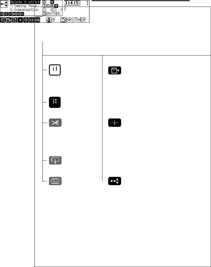
Screen Composition
Initial Screen
Starting Sewing |
|
|
|
|
|
Selection of Embroidery data |
|
|
|
|
|||
START |
|
|
|
|
|
|
Operation (→ page 72) |
|
|
|
|
|
(→ page 61) |
Canceling of Sewing |
|
|
STOP |
|
|
Thread trimming |
|
Setting of Needle Bars |
|
||
|
|
(→ page 92) |
Hoop Retract
Area Check |
|
Editing of Enbroidering Data |
|
||
|
|
(→ page 77) |
↓
↓
10 |
BES-961BC • BES-1261BC |
Setting of thread breakage sensor (→page 93)
↓
↓
Setting of Machine (→page 96)
↓
↓
BES-961BC • BES-1261BC |
11 |

Contents
SAFTY INSTRUCTIONS............................................................................... |
1 |
Before Starting Operation .......................................................................... |
6 |
Procedure of Reading This Manual ........................................................... |
8 |
Screen Composition ................................................................................. |
10 |
Chapter 1 |
Preparation of Embroidery Machine |
|
|
1. |
Specifications ..................................................................................... |
18 |
|
2. |
Names of Machine Components ....................................................... |
19 |
|
3. |
Installation ........................................................................................... |
21 |
|
|
3-1. |
Transportation of Machine ..................................................................... |
21 |
|
3-2. |
Installation of Machine ........................................................................... |
23 |
|
3-3. Preparation of Needle Bar Case ............................................................ |
24 |
|
|
3-4. |
Mounting of Table .................................................................................. |
26 |
|
3-5. Mounting of Cotton Stand ...................................................................... |
30 |
|
|
3-6. Lubrication to Needle Bar Case ............................................................. |
32 |
|
|
3-7. |
Grounding .............................................................................................. |
33 |
4. |
Preparation for Embroidering ............................................................ |
34 |
|
|
4-1. |
Upper Threading .................................................................................... |
34 |
|
4-2. |
Replacement of Bobbin .......................................................................... |
37 |
|
4-3. Replacing and Selecting Needle ............................................................ |
38 |
|
|
4-4. Attachment of Embroidery Hoop and Frame ......................................... |
39 |
|
|
4-5. |
Bed Retract ............................................................................................ |
45 |
|
4-6. Adjustment of Thread Tension ............................................................... |
47 |
|
Chapter 2 Embroidering Procedures |
|
Functions of Operation Panel .................................................................. |
50 |
Operation Panel ................................................................................................ |
50 |
Switches at Machine Heads .............................................................................. |
53 |
Switches on Tension Plate ................................................................................ |
53 |
Flowchart of Preparation for Embroidering ............................................ |
55 |
Turn on the Machine Power .............................................................................. |
56 |
Retrieve the Embroidery Data ........................................................................... |
57 |
Start Embroidering ............................................................................................ |
57 |
Chapter 3 Selection of Data and Embroidering
What Can the Machine Do? ...................................................................... |
60 |
Selection of Embroidery Data ........................................................................... |
60 |
Embroidering Operation .................................................................................... |
60 |
Selection of Data ....................................................................................... |
61 |
Registration of Embroidery Data from Floppy Disk ........................................... |
61 |
12 |
BES-961BC • BES-1261BC |

Reading from Memory .............................................................................. |
64 |
|
Registration of Embroidery Data from BE-100 ....................................... |
65 |
|
Deletion of Embroidery Data from Machine Memory ........................................ |
66 |
|
Modification of Embroidery Data Name .................................................. |
68 |
|
Sewing Operation ...................................................................................... |
72 |
|
Before Starting Sewing ..................................................................................... |
72 |
|
Starting Sewing Operation ................................................................................ |
72 |
|
Feedhold and Cancellation of Sewing ............................................................... |
73 |
|
Step Forward and Step-Back ................................................................... |
74 |
|
Step Forward/Step-Back Mode ......................................................................... |
74 |
|
Setting Amount or Timing of Step Forward/Step-Back ..................................... |
74 |
|
For Step Forward (Back) ................................................................................... |
75 |
|
Resuming Sewing ............................................................................................. |
75 |
|
Chapter 4 |
Editing Embroidering Data |
|
What Can the Machine Do? ...................................................................... |
78 |
|
Editing ............................................................................................................... |
|
78 |
Rotation ...................................................................................................... |
|
79 |
Enlargement and Reduction..................................................................... |
80 |
|
Mirror .......................................................................................................... |
|
82 |
Repetition ................................................................................................... |
|
84 |
Other Editing.............................................................................................. |
86 |
|
Chapter 5 |
Settings |
|
What Can the Machine Do? ...................................................................... |
90 |
|
Setting of Needle Bars ...................................................................................... |
90 |
|
Setting of Thread Breackage Sensor ................................................................ |
90 |
|
Setting of Machine ............................................................................................ |
90 |
|
Setting of Environmenet .................................................................................... |
91 |
|
Display of Information ....................................................................................... |
91 |
|
Hoop Retract point ............................................................................................ |
91 |
|
Hoop Movement ................................................................................................ |
91 |
|
Setting of Needle Bars .............................................................................. |
92 |
|
Thread Breakage Sensor .......................................................................... |
93 |
|
Setting of sensor validity/invalidity .................................................................... |
93 |
|
Thread Breakage Sensitivity ............................................................................. |
93 |
|
Automatic Step-Back ......................................................................................... |
94 |
|
Setting of Lower Thread Counter/Stitch Counter .............................................. |
95 |
|
Setting of Machine .................................................................................... |
96 |
|
Embroidery Hoop .............................................................................................. |
96 |
|
Speed Range .................................................................................................... |
97 |
|
BES-961BC • BES-1261BC |
13 |
Speed of Each Speed Range ............................................................................ |
98 |
Setting of Mending ............................................................................................ |
99 |
Thread Trimming Length ................................................................................. |
101 |
Thread Withdrawal Feed Length ..................................................................... |
101 |
Inching ............................................................................................................. |
102 |
Sewing Area .................................................................................................... |
103 |
Registration of Sewing Start Position .............................................................. |
103 |
Hoop Retract Point .......................................................................................... |
104 |
Hoop Automatic Retract .................................................................................. |
104 |
Movement to Registered Sewing Start Point .................................................. |
105 |
Setting of Environment ........................................................................... |
106 |
Return to Start Point ........................................................................................ |
106 |
Speed Range .................................................................................................. |
107 |
Power Voltage ................................................................................................. |
107 |
Setting of RS-232C Communication Speed .................................................... |
108 |
Display Language ........................................................................................... |
109 |
Alarm Sound ................................................................................................... |
110 |
Boring .............................................................................................................. |
111 |
Display of Information ............................................................................ |
113 |
Pattern Information .......................................................................................... |
113 |
Features of Machine ....................................................................................... |
114 |
Information about Versions ............................................................................. |
115 |
Chapter 6 |
Operation of Machine |
|
|
1. |
Operating Procedures ...................................................................... |
118 |
|
|
1-1. |
Power Source ...................................................................................... |
118 |
|
1-2. |
Preparation for Embroidering ............................................................... |
118 |
2. |
Machine Stop .................................................................................... |
119 |
|
|
2-1. |
Stopping of Machine ............................................................................ |
119 |
|
2-2. |
Resetting Emergency Stop .................................................................. |
119 |
3. |
Measures against Thread Breakage ............................................... |
120 |
|
|
3-1. |
Remedies ............................................................................................. |
120 |
|
3-2. |
Mending ............................................................................................... |
122 |
4. |
Jog Embroidering ............................................................................. |
123 |
|
5. |
Hoop Feed Position .......................................................................... |
123 |
|
6. |
Area Check ........................................................................................ |
124 |
|
|
6-1. |
External Tracing ................................................................................... |
124 |
|
6-2. Automatic Hoop Movement in Area ..................................................... |
124 |
|
7. |
Jog Switches ..................................................................................... |
125 |
|
|
7-1. Hoop Movement to Start Position ........................................................ |
125 |
|
|
7-2. Inching Mode during Embroidering (Forcible Hoop Movement) .......... |
126 |
|
8. |
Detection of Zero Point .................................................................... |
127 |
|
14 |
BES-961BC • BES-1261BC |

Chapter 7 |
Maintenance |
|
|
1. |
Cleaning Rotary Hook ...................................................................... |
130 |
|
2. |
Oiling |
.................................................................................................. |
131 |
|
2-1. |
Head .................................................................................................... |
131 |
3. |
Greasing ............................................................................................ |
133 |
|
|
3-1. |
Head .................................................................................................... |
133 |
|
3-2. |
Feed Guide Section ............................................................................. |
137 |
Chapter 8 Standard Adjustment |
|
||
1. |
Adjusting Needle Bar Height ........................................................... |
140 |
|
2. |
Replacing (Attaching) Rotary Hook ................................................ |
144 |
|
3. |
Adjustment of Clearance Between Needle and Rotary Hook ....... |
145 |
|
4. |
Adjustment of Timing Between Needle and Rotary Hook ............ |
146 |
|
5. |
Adjustment of Presser Foot Height ................................................ |
147 |
|
6. |
Adjustment of Thread Trimmer ....................................................... |
148 |
|
|
6-1. |
Attaching the Fixed Knife ..................................................................... |
148 |
|
6-2. |
Checking the Movable Knife Position .................................................. |
148 |
|
6-3. |
Adjusting the Belt Tention .................................................................... |
150 |
|
|
|
|
Chapter |
9 List of Error Message |
|
|
Chapter 10 Troubleshooting
Mechanical Section ................................................................................. |
156 |
Electrical Section .................................................................................... |
158 |
Connection and Installation of Optional Equipment
Attaching Bobbin Winder ....................................................................... |
160 |
BES-961BC • BES-1261BC |
15 |
16 |
BES-961BC • BES-1261BC |

Chapter 1
Preparation of Embroidery Machine

Chapter 1 Preparation of Embroidery Machine
1. Specifications
Embroidery machine used |
9 needle embroidery machine head |
12 needle embroidery machine head |
|||
(six-head type) |
(six-head type) |
||||
|
|||||
|
|
|
|
|
|
Application |
Pattern embroidery |
|
|
|
|
|
|
|
|
||
Sewing speed |
Maximum 1000 spm |
|
|||
|
|
|
|||
|
450 (V) x 400 (H) mm (border frame area) |
||||
Sewing area |
430 (V) x 300 (H) mm (tubular square hoop area) |
||||
85 (V) x 360 (H) mm (cap frame area) |
|||||
|
|||||
|
450 (V) x 600 (H) mm (with bed retracted or with head control) |
||||
|
|
|
|||
Feed system |
By timing belt and stepping motor drive |
||||
|
|
|
|||
Stitch length |
0.1 ~ 12.7 mm (minimum pitch: 0.1 mm) |
||||
|
|
|
|
||
|
3.5 2DD floppy disk (Tajima format) |
|
|||
Storage medium |
3.5 2HD floppy disk (the equivalent to Tajima format) |
||||
|
3.5 2DD floppy disk (Barudan FDR/FMC format) |
||||
|
|
|
|
||
Thread trimming |
Automatic thread trimmer |
|
|||
|
|
|
|
||
Needle thread breakage |
Needle thread breakage detector |
|
|||
|
|
|
|||
Power supply |
Single phase 200 V, 220 V, 230 V, 240 V,1.7 kVA |
||||
|
|
|
|
|
|
Weight |
720 kg |
|
|
720 kg |
|
|
|
|
|
||
|
(Before assembly) |
3650 (W) x 810 (L) x 1650 (H) mm |
|||
Dimensions |
(After setup) |
3650 (W) x 1400 (L) x 1650 (H) mm |
|||
|
(Distance between machine heads) 400 mm |
||||
|
|
|
|
||
Options |
Embroidery hoops in different sizes, |
Bobbin winder, |
|||
Parts for boring |
|
|
|
||
|
|
|
|
||
|
|
|
|
|
|
18 |
BES-961BC • BES-1261BC |

Chapter 1 Preparation of Embroidery Machine
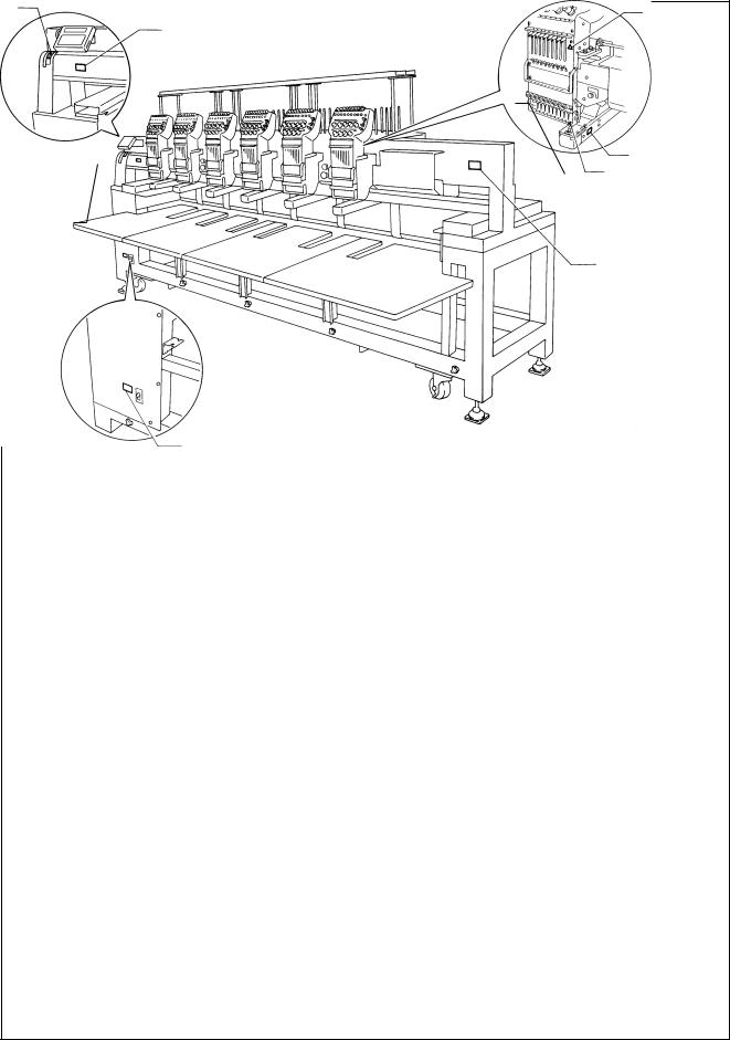
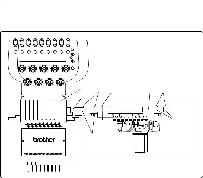
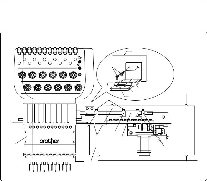
2. Names of Machine Components
■ BES-961BC
|
Thread tension switch |
||
|
Thread |
Thread guide B |
|
Thread tension dial |
Thread guide C |
||
guide A |
|||
|
|||
Cotton stand
Operation panel
Pulley
Start switch 
Emergency stop switch
Control box
Power switch
F table
Start switch
Emergency stop switch
Leg
Thumb bolt
■ BES-1261BC
|
Thread tension switch |
Thread guide B |
|
Thread tension dial |
Thread |
Thread guide C |
|
guide A |
|||
|
|||
|
|
||
Operation panel |
|
Cotton stand |
|
Pulley |
|
|
Control box
Power switch
F table
Head switch
Leg
Thumb bolt
The machine heads are numbered 1 to 6 from the right front.
BES-961BC • BES-1261BC |
19 |

Chapter 1 Preparation of Embroidery Machine
■ Accessories
|
Standard Accessories |
Optional Accessories |
Embroidery hoop |
• Tubular square hoop 30 x 43 (6) |
• Holder base 30 x 43 (6) |
|
• Tubular round arm set R (6) |
Other embroidery hoops in different sizes |
|
• Tubular round arm set L (6) |
|
|
|
• Sash frame assembly |
|
|
* Other Tajima embroidery hoops that can |
|
|
be used with BAS-412A and 416A |
|
|
• Cap frame (6) |
|
|
Cap frame drive assembly (6) |
|
|
Base frame set (12) |
|
|
Set frame base set (1) |
|
|
|
Others |
F table assembly |
• Bobbin winder |
|
|
• Parts for boring |
|
|
|
20 |
BES-961BC • BES-1261BC |
Chapter 1 Preparation of Embroidery Machine
3. Installation
 DANGER
Embroidery machines should be installed only by trained engineers.
Electric wiring should be laid by your distributor or electric experts.
A machine weighs more than 720 kg. Installation should be carried out by 4 or more workers.
Do not connect the power source until installation is completed. Doing so may start the machine unintentionally through an accidental activation of the START switch, resulting in bodily injuries.
Install a machine in a place away from a highfrequency welding machine or other machines that may generate a strong electric noise. Failure to do so may cause the embroidery machine to malfunction.
Establish grounding as designated. Improper grounding may result in an electric shock.
*After installation is completed, get the power supply from a dedicated outlet.
*When connecting multiple machines, exercise care not to exceed the capacity of the outlet.
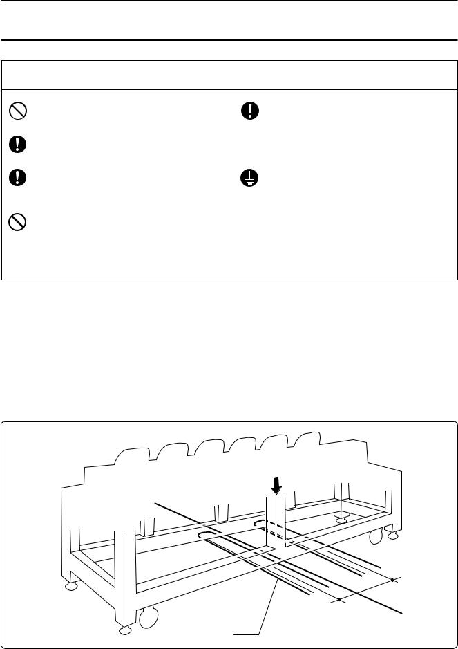
3-1 Transportation of Machine
When relocating the machine, push the steel frame.
Note) Never push the cover or carriage.
■ When using a fork lift
Center pillar
a a+20
Lift forks
Open the forks of the lift approximately 10 cm to the right from the even position to the center pillar viewed from the rear of the machine, and pass them under the legs to lift the machine.
BES-961BC • BES-1261BC |
21 |

Chapter 1 Preparation of Embroidery Machine
■ When using a crane
Rope
L-shaped steel
Rectangular bar
Place two rectangular bars on the four L-shaped steels on the bottom of the machine steel frame. Loop four ropes around the bars and lift the machine.
Note) When lifting the machine, make sure that the ropes do not contact the machine table or the tension plate.
22 |
BES-961BC • BES-1261BC |
Chapter 1 Preparation of Embroidery Machine
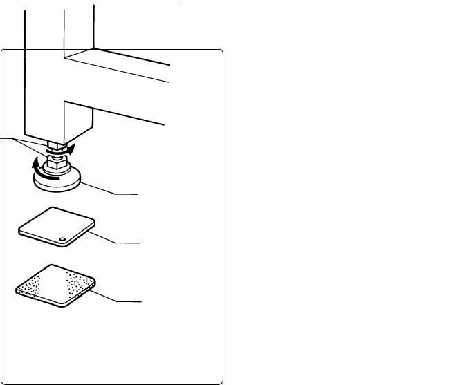
3-2 Installation of Machine
1. Place the attached cushion sheets w and leveling plates e under the four level adjusters q. The leveling plates e should be placed above the cushion sheets respectively.
2. Secure the four level adjusters q on the ground using the nuts r so that the machine will be stable.
Note) If the floor is not strong enough, the embroidery machine may be rocked during opera- r tion. In such a case, it is recommended that a secure base of concrete be placed below the
embroidery machine.
q
e
w
BES-961BC • BES-1261BC |
23 |
Chapter 1 Preparation of Embroidery Machine
3-3 Preparation of Needle Bar Case
■ BES-961BC
w |
q |
y |
e i |
|
|||
u |
|
|
|
r
t
1.Loosen the bolt q, and move the needle case w to the left.
2.Press the change bracket collar r against the change case base e on the light, while pressing the change bracket collar t against the change case base y on the left, and tighten the bolt q. Check that needles at needle bar No.1 and 9 are inserted into the needle plate holes smoothly.
Note) • Check that the connecting shaft u does not have backlash in the horizontal direction.
•If the bolt i of the change bracket collar on the right is loosened, it may be dislocated during adjustment of the needle bar case w. Do not loosen this bolt.
24 |
BES-961BC • BES-1261BC |
Chapter 1 Preparation of Embroidery Machine
■ BES-1261BC
Bridge
r
|
Connecting shaft |
q |
|
Fixing bracket |
|
t |
Fixing bracket B |
|
|
o |
|
|
|
o |
|
q |
u |
|
|
|
y |
|
i |
|
|
w
e
1.Remove 3 pieces of fixing screw q,loosen 2 pieces of screw w and remove the color change cover e.
2.Remove the bolts r and detach the fixing bracket for transportation from the bridge and the connecting shaft.
3.Loosen the bolts t and move the needle bar case y left side.
4.Press the change bracket collar i against the change case base u, while pressing the left side change bracket collar o against the change case base u, and tighten the bolts t.Check that needle bar No.1 and 12 are inserted into the needle plate holes smoothly.
(Notes) • Check that ther is no play for the connecting shaft in the horizontal direction.
•If the bolt of the right side change bracket collar i is loosened, the change bracket collar i may be dislocated and adjusting position of the needle bar case y will be required. So don’t loosen this bolt.
5.Attach the color change cover e by 3 pieces of fixing screw q and 2 pieces of fixing screw w.
BES-961BC • BES-1261BC |
25 |
Chapter 1 Preparation of Embroidery Machine
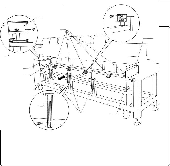
3-4 Mounting of Table
■ Mounting of F table
q
r
q
w
q
w
e
e w
1.Tentatively mount the F table guides U q and L w on both sides of the legs using two bolts each.
2.Tentatively mount there F table supports F e on the leg front using two bolts each.
3.Tentatively mount five F table stoppers r on the rear legs using two bolts each.
Note) • The steps 1 and 3 are required only when the F table set is purchased separately from the machine.
• The F table is a standard attachment.
26 |
BES-961BC • BES-1261BC |
Chapter 1 Preparation of Embroidery Machine
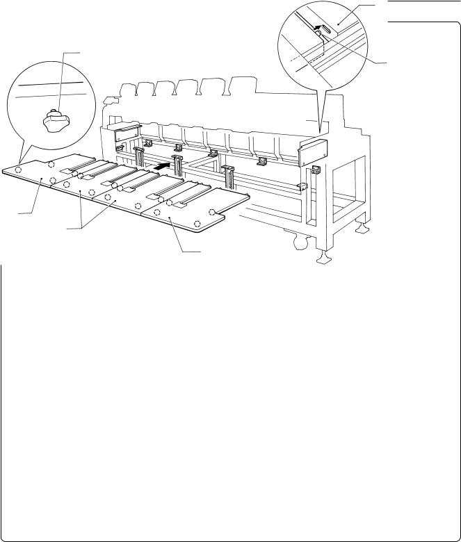
o
i
Pin
t
y
u
q
Lower by 1 mm
e
4.Mount four thumb bolts i each on the rear of F table R t, M (2 pcs.) y, and L u.
5.Mount five thumb bolts on the steel pipe below the front leg.
6.Insert the pins attached to the rear of the F table R t, M (2 pcs.) y, and L u into the cover o on the leg. Adjust the height of the F table guide U q and the F table support F e so that the table top surface will become 1 mm lower than the bed top surface. After adjustment is finished, tighten each bolt securely.
BES-961BC • BES-1261BC |
27 |
Chapter 1 Preparation of Embroidery Machine
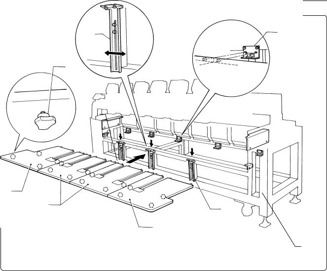
e |
r |
|
i
w
u
y
e
w
t
7.Dismount the F table R t, M (2 pcs.) y, and L u once, and lower the F table support F e. Then, place the F table R t, M (2 pcs.) y, and L u on the F table guide L w bending section. Fix the F table support F e at this height and insert the pins on the rear of the F table R t, M (2 pcs.) y, and L u into the holes of the F table stopper r.
Note) Fix the F table stopper and the F table guide L securely at this position.
8.Insert the F table R t, M (2 pcs.) y, and L u into the upper and lower positions respectively, then check if the table can be securely fixed by the thumb bolts i. If not, shift the F table support F e to the right and left for further adjustment.
28 |
BES-961BC • BES-1261BC |
Loading...