Broan 1052-B User Manual

TRASH COMPACTOR
SERVICE MANUAL
MODELS | MODEL |
This service manual is only for compactor models shown.
Service manuals for additional compactor models are available from your Broan representative.

CONTENTS |
|
Safety Precautions ................................................................... | 2 |
Model and Serial No. Identification ......................................... | 2 |
Transporting Compactor .......................................................... | 2 |
Manually Raising and Lowering Ram ...................................... | 2 |
Troubleshooting Guide ...................................................... | 3 & 4 |
Component Replacement ............................................... | 5, 6 & 7 |
Greasing Compactor Mechanism ............................................. | 7 |
Wiring Diagrams ...................................................................... | 8 |
Parts Lists .................................................................... | 9 thru 12 |
SAFETY PRECAUTIONS |
|
ALWAYS UNPLUG COMPACTOR FROM WALL OUTLET BEFORE SERVICING.
The service information is intended for use by a service technician who is familiar with proper and safe procedures to be followed when repairing electrical appliances and who is equipped with proper tools and testing devices. Repairs attempted or made improperly can result in personal injury or property damage. Hazards may develop from improper assembly or adjustments. While making repairs, persons not having the proper background may subject themselves to the risk of injury or electrical shock which can be serious or even fatal.
IMPORTANT - NOTE TO THE CONSUMER
If you perform service on your own Broan products, you must assume responsibility for personal injury or property damage which may result.
MODEL AND SERIAL NO. IDENTIFICATION
The specification label with model and serial numbers is located on the inside of the cabinet. It is visible after opening the drawer.
TRANSPORTING COMPACTOR
When transporting compactor, the ram should be electrically or manually extended down into the drawer, preferably against a load of stacked newspapers or other suitable material. If this is not done, damage to the trunnion nut may occur.
Never transport compactor on its back or front. Damage to the gearbox may occur. If it cannot be transported upright, it is preferable to place it on its side.
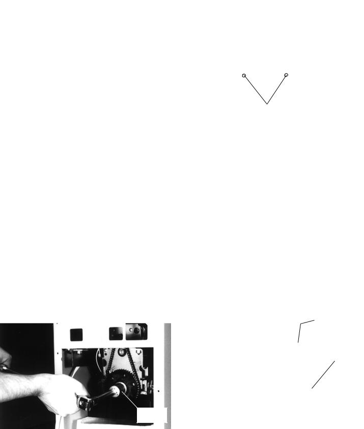
MANUALRAISINGAND LOWERING OF RAM
Unplug compactor cord from wall socket. Remove back panel. The ram may be raised or lowered manually by using a 15/16" socket to turn the drive screw nut. Clockwise will lower ram, counterclockwise will raise it.
15/16” SOCKET
2
BAG INSTALLATION
DO NOT use plastic bags other than those which have been designed for use in this compactor. Unauthorized bags can become caught in the mechanism.
With the drawer extended to the second stop, release the container latch and swing open door. Slide bag into drawer from front to back. Fold bag over top rim of drawer on all sides.
PREPUNCHED HOLES
Press bag into all corners of the drawer. Smooth and shape the bag carefully - this will prevent the bag from being torn by the ram during compaction.
DRAWER BUTTONS
Using buttons on side of drawer, button bag in place by using prepunched holes in side of bag. NOTE: If you have difficulty installing bag, move drawer to second stop by lifting front of drawer slightly and pulling forward (place on rug or other surface to protect floor). This
will clear back of container from housing for easier bag installation.
Swing door shut and latch it. Bag is locked between door flange and drawer. When door is closed and latched properly, door guide “V” will be snug in “V” groove in drawer flange. Bag should be captured in “V” guide. Failure to align “V” properly or to latch drawer to door will cause the compactor to function improperly.
“V” GROOVE
CONTAINER
LATCH

TROUBLESHOOTING GUIDE
Condition |
| Possible Cause |
| Correction |
I. Will not run. Dead - | Not plugged in securely. |
| Insert plug securely into | |
no sound. (Turn key |
|
| outlet. | |
to start, if unit hums, | Circuit breaker or fuse |
| Check for condition | |
go to section III. |
| |||
|
| open. |
| causing circuit breaker |
|
|
|
| or fuse to open. Correct |
|
|
|
| condition, then reset |
|
|
|
| circuit breaker or replace |
|
|
|
| fuse. |
|
| Drawer not closed. |
| Push drawer to close. |
|
| Loose connection. |
| Repair. |
|
| Defective key switch. |
| Replace. |
|
| Defective motor. |
| Test motor - replace if |
|
|
|
| necessary. |
II. Runs continuously, | Sprocket broken. |
| Replace. | |
will not shut off. | Chain derailed. |
| Reinstall chain. | |
|
|
| ||
|
| Gearbox broken. |
| Replace. |
|
| Trunnion nut stripped. |
| Replace. |
|
| Key switch incorrectly |
| Reconnect correctly. |
|
| connected. |
|
|
|
| Defective upper limit |
| Replace. |
|
| switch. |
|
|
Special Notes
Compactor should be on separate 15 ampere circuit
See section on motor replacement for test procedure.
See note in section covering chain derailment.
Inspect trunnion nut for any evidence of damage. If nut displays signs of thread destruction, replace nut, clean drive screw and regrease.
III. Will not run - hums | Defective upper limit | Replace. |
|
when key held in | switch. |
|
|
start position. | Loose connection. | Repair. |
|
|
| ||
| Defective motor. | Test motor - replace if | See section on motor |
|
| necessary. | replacement for test |
|
|
| procedure. |
| Plastic bag caught in | Remove plastic bag. | See section on removing |
| trunnion nut. |
| bags from tunnion nut. |
|
|
| Do not use bags other |
|
|
| than the compactor trash |
|
|
| bag designed and sold |
|
|
| by Broan for use in this |
| 3 |
| compactor. |
TROUBLESHOOTING GUIDE
Condition |
| Possible Cause |
| Correction |
| Special Notes |
IV. Starts and reverses |
| Defective upper limit |
| Replace. | It is not necessary to | |
immediately. Will not |
| switch. |
| Try again. | replace motor. | |
go down into drawer. |
| Didn’t hold key long |
|
| ||
Rhythmic buzzing. |
| enough. |
|
|
|
|
V. Thermal cutout on |
| Defective upper limit |
| Replace. |
| |
motor trips. (Com- |
| switch. |
|
|
|
|
pactor may appear to |
| Defective centrifugal |
| Replace. |
| |
start by itself several |
|
|
| |||
minutes after last |
| switch on motor. |
|
|
|
|
use.) Smells hot. |
|
|
|
|
|
|
VI. Drawer does not |
| Worn rollers. |
| Replace. | Roller tracks should be | |
open smoothly after |
| Bent roller mounting |
| Straighten bracket. | kept clean to keep glass | |
compactor is leveled. |
|
| particles from wearing | |||
|
| bracket. |
|
|
| out rollers. |
|
| Tight roller track on |
| Bend top rail on track to |
| |
|
| base. |
| adjust. |
| |
|
| Latch binding on side of |
| Bend to adjust. |
| |
|
| cabinet. |
|
|
|
|
|
| Defective drawer track. |
| Replace drawer. |
| |
|
| Loose roller(s). |
| Tighten. | Apply Locktite® to | |
|
|
|
|
|
| threads. |
VII. Does not compact |
| Insufficient amount of |
|
|
| Ram does not travel to |
cans. Lacks pres- |
| trash in drawer. |
|
|
| bottom of drawer. Ex- |
sure. |
|
|
|
|
| tends to 6" from bottom |
|
|
|
|
|
| of basket. As more trash |
|
|
|
|
|
| is deposited and unit is |
|
|
|
|
|
| operated, compaction |
|
|
|
|
|
| will take place. |
|
| Bottles and/or cans are |
|
|
| Bottles and cans should |
|
| arranged too uniformly. |
|
|
| be placed randomly in |
|
|
|
|
|
| center of drawer. Cans |
|
|
|
|
|
| and bottles neatly |
|
|
|
|
|
| arranged are capable of |
|
|
|
|
|
| supporting a tremendous |
|
|
|
|
|
| amount of pressure. |
| Lacking grease. | Grease drive screw and |
|
| trunnion bearing using |
|
| wheel bearing grease. |
| Worn rear trunnion | Replace trunnion bear- |
| bearing. | ing. |
VIII. Bags pulled down | Using bags designed for | Use Broan compactor |
into drawer. | another manufacturer”s | bags. |
| compactor. |
|
| Improper installation of | Install bag correctly. |
| bag. | 4 |
|
|
See section on greasing mechanism.
Bag should be captured in “V” groove on right front of drawer.

CABINET REPLACEMENT - POWER PACK REMOVAL
A box or similar stand approximately 11” high x 15” long x 7” wide is recommended for power pack removal. The box must be able to support 60 lbs. or more since you will be placing the full weight of the power pack on it.
1.Unplug compactor from socket.
2.Remove drawer assembly from cabinet.
3.Remove Air Scentry tray and control panel.
4.Remove key switch control bracket assembly. Remove back panel.
5.Place box in cabinet and lower ram manually by turning 15/ 16" nut on sprocket clockwise. Box should support weight of power pack.
6.Remove the four 5/16" nuts supporting the power pack in the cabinet.
7.Disconnect ground wire attached to cabinet.
8.Turn 15/16" nut counterclockwise causing power pack to lower down out of cabinet. Pull power pack out through front of rear of compactor.
If you are replacing the cabinet, remove remaining parts from old cabinet and install on new. See appropriate sections of service manual.
Reverse procedure to install power pack. Be sure the weld strip, grommets, and spacers are in place. The lock nuts should be torqued to 5 ft./lbs. (60 inch/lbs.). Do not overtorque.
Be careful not to pinch or nick any wires when installing power pack in cabinet.
|
|
|
|
|
|
WELD | STRIP | GROMMETS | |||
|
| SPACERS | |||
|
|
|
|
POWER PACK
MOUNTING
LOCK NUTS
CONTROL PANEL
On units with a bag storage compartment, removal of the storage compartment will make replacement of the control panel easier.
1.Remove drawer assembly.
2.Remove the four screws securing the air scentry tray and the bottom of control panel to the cabinet.
3.Pull bottom of control panel out slightly and then up.
When installing the control panel, make sure lip on inside of control panel snaps behind the bend in the control panel bracket.
STORAGE COMPARTMENT
Remove two screws on rear of compactor and the two 5/16" hex head screws inside the storage compartment. Slide compartment back and lift off.
DRAWER ASSEMBLY
1.Pull out drawer until it stops.
2.Lift drawer slightly, then pull out drawer to second stop.
3.Lift drawer up and out of compactor.
FOOT PEDAL (MODELS 1050 & 1051 ONLY)
1.Remove foot pedal retainers from each side of pedal.
2.Push foot pedal hinge pin out, catch foot pedal spring as it comes free.
DOOR LINER
Remove the door from the drawer by unlatching the door and removing the hinge pins. The door liner can be removed from the door by removing the toe space cover and all screws holding the door liner to the door. Slide the door liner to side of door and lift off. (Models 1050 and 1051 will require removal of the foot pedal prior to toe space cover.)
DRAWER AND BASE ROLLERS
All four of the rollers are secured with a 1/2" hex nut and slotted for screwdriver. Roller nuts are installed using LocktiteR and torqued to 20 foot pounds. Rollers are pregreased and should require no lubricant.
BOTTOM ASSEMBLY
1.Unscrew level legs from base. Remove tee nuts that legs screw into.
2.Remove screws securing bottom assembly to the cabinet.
3.Lower the bottom down into the cabinet, back end first, then bring it up and out through the notches in the bottom flange of the cabinet.
5

SWITCH LOCATIONS KEY SWITCH
INTERLOCK
SWITCH
UPPER LIMIT
SWITCH
the door. Another switch located against the interlock switch is the door. Another switch located against the interlock switch is to provide the
TO REPLACE INTERLOCK SWITCH
1.Remove air scentry panel assembly.
2.Disconnect leads one by one and attach to new switch.
KEY SWITCH
1.Remove control panel.
2.Remove two hex head screws supporting control panel bracket with 5/16" socket.
3.Pull bracket out and remove switch.
| KEY |
|
|
| |
|
| CONTROL PANEL BRACKET | |||
| SWITCH |
|
|
|
|
|
|
|
|
|
TRUNNION NUT
1.Remove back panel, drawer assembly and air scentry panel.
2.Lower ram manually to approx.
3.Remove screws from nut retainer.
4.Raise ram assembly slightly by hand and remove nut.
NOTE: Count the number of revolutions to spin off nut. TRUNNION must be reinstalled to same position.
5. Reinstall trunnion nut and retainer.
CONTINUAL STRIPPING OF TRUNNION NUT: POSSIBLE CAUSES:
1.Incorrect assembly of trunnion assembly.
2.Transporting compactor incorrectly.
3.Burr on main drive screw; sharp edge on
4.Upper limit switch adjustment.
UPPER LIMIT SWITCH
1.Remove drawer assembly.
2.Lower ram to gain access to switch.
3.Remove air scentry tray.
4.Remove hex head screw with 5/16" socket, pull switch down and disconnect wires.
Check | Switch not | Switch |
Continuity | Activated | Activated |
3 to 1 | closed | open |
2 to 1 | open | closed |
6 to 1 | open | open |
3 to 4 | open | open |
6 to 4 | closed | open |
5 to 7 | open | closed |
| |
| |
| |
| |
|
REMOVING PLASTIC BAGS FROM TRUNNION NUT
Only the trash compactor bags specifically designed and sold by Broan for use in the compactor should be used. Regular plastic garbage bags used in place of the Broan bags may be drawn into the mechanism. Removal of those bags is not covered by the warranty.
To remove bag from trunnion nut:
1.Remove back of compactor.
2.If possible to slide drawer slightly, remove the door by sliding out the two hinge pins and then prying the door over the lip on the drawer.
3.Liberally spray drive screw and trunnion nut with
4.Use 15/16" socket, and extension, and a 16" ratchet (for leverage) and manually turn the drive screw clockwise. (See section on manually raising and lowering ram.) By turning the drive screw clockwise, you will help back the bag out of the trunnion nut.
5.After removing bag, clean drive screw and regrease it with wheel bearing grease.
INTERLOCK SWITCH | DRIVE SCREW | ||
1. | Lower ram manually approximately halfway. | ||
The interlock switch is a | 2. | Remove sprocket. | |
type. It is located on the right side behind the air scentry panel. | 3. | Remove 1/4" drive pin. Slide off washers. | |
Its contacts are normally open. the contacts close when the door | |||
6 4. | Lift ram, causing drive screw to slide out of the motor trun- | ||
is closed. It is activated by the actuator located on the back of |
nion bearing. Support motor/gearbox assembly since it is now free to pivot. Unscrew drive screw from front trunnion assembly.

TRUNNION BEARING | GEARBOX |
1.Remove sprocket and drive pin.
2.Pull out trunnion bearing.
Grease trunnion bearing inside and out with wheel bearing grease prior to reinstalling.
MOTOR TRUNNION
1.Remove motor, gearbox, spocket, and screw guard.
2.Use 13/16" wrench to remove bolts securing links to motor trunnion.
When reinstalling, bolts should be torqued to 45 foot pounds.
SPROCKET
1.Line up one of the 3/8" holes in the sprocket with the 3/8" hole in bottom center of gearbox. Insert 3/8" steel pin or bolt through sprocket hole into front and rear gearbox holes.*
2.Loosen and remove 15/16" nut on the drive screw. When reinstalling torque to 65 foot pounds and apply Locktite® to threads.
*If the sprocket is too damaged to be able to use on of the holes to secure it, chip away the remaining sprocket, remove the drive pin and then insert a screwdriver through the hole to provide a means of keeping the drive screw from turning.
INSERT
3/8” DIA. PIN
1.Lower ram manually until there is approximately 11" to 12" between the ram and the bottom assembly.
2.Remove the four 3/8" nuts securing motor to gearbox, slide motor out and rest it on the front trunnion assembly.
3.Turn sprocket until two holes in sprocket line up with the two socket head cap screws that hold the gearbox to the motor trunnion.
4.Remove the two socket head cap screws with a 5/32" hex key. NOTE: The screws thread into 2 nuts which rest in slots in the motor trunnion. Be careful not to lose the 2 nuts when the screws are removed.
5.Tilt gearbox forward and remove chain. Lift gearbox out.
When installing gearbox, Locktite® should be applied to the socket head cap screw nuts.
5/32” HEX KEY
CHAIN
1. Turn sprocket until two holes in sprocket line up with socket
head cap screws. |
|
|
|
2. Remove socket head cap screws and tip gearbox/motor as- |
|
|
|
sembly to remove chain. NOTE: The screws thread into 2 |
|
|
|
nuts which rest in slots in the motor trunnion. Be careful not |
|
|
|
to lose the 2 nuts when the screws are removed. |
| GREASING COMPACTOR | |
When reinstalling socket head cap screws, be sure Locktite® is |
| ||
applied to the nuts. |
| MECHANISM | |
Chain Derailment: Loose chains. Sometimes a chain will derail |
| ||
| 1. | Unplug compactor from wall outlet. | |
because trash which flew up above the ram during compacting |
| ||
| 2. | Remove drawer assembly from compactor. | |
fouled the chain. Newspaper or a paper bag should be placed on |
| ||
top of glass bottles before compacting to prevent this. |
| 3. | Remove back of compactor and lower mechanism manually |
If continual derailment of the chain is a problem, inspect both |
|
| by turning 15/16" nut on sprocket clockwise. |
sprockets for worn or missing |
| 4. | Line up one of the holes in the black sprocket with the hole in |
teeth. Inspect gearbox mount- |
|
| the gearbox. Insert a 3/8" bolt or pin to keep sprocket from |
ing and mounting plate. If the |
|
| turning and remove the 15/16" nut. |
mounting screws are loose, |
| 5. | Slide off sprocket and washer. |
gearbox movement may be the |
| 6. | Drive out the drive pin, slide off thin washer and pull out |
cause. If the gearbox mounting |
| ||
|
| trunnion bearing. | |
plate is bent where it meets the |
|
| |
| 7. | Grease trunnion bearing everywhere, inside and out, with | |
motor trunnion, either straight- |
| ||
|
| regular wheel bearing grease. | |
en or replace the gearbox. |
|
| |
| 8. | Reassemble unit in reverse procedure. When reinstalling 15/ | |
Some chain looseness is nor- |
| ||
|
| 16" nut, be sure to apply a drop of Locktite® or equivalent to | |
mal and may increase as the |
|
| |
|
| the threads of the 15/16" nut. | |
compactor is used. Seldom |
|
| |
| Apply grease to length of drive screw and a dab to the scissor | ||
does the chain “stretch” to the |
| ||
point where it is too loose. | 7 | links at the pivot points. | |
|
|
|

MOTOR
Before motor is removed, it should be tested to be sure it is inoperative. Check the continuity of the motor.
CHECK CONTINUITY |
|
Black to Orange | If open, replace motor |
Red to Orange | If open, replace motor |
Gray to Orange | If open, replace motor |
Green to Motor Frame | If open, inspect wire to |
| be sure it is properly |
| attached to motor |
| frame |
1.Lower ram manually until there is approximately 7" between the bottom assembly and the ram.
2.Disconnect molex connector from motor to wire harness.
3.Using a 3/8" nut driver or socket, remove the four nuts holding the motor to the gearbox. Remove air scentry tray and pull motor out through front of compactor.
4.Install motor in reverse procedure.
BLACK GRAY
RED GREEN
ORANGE
EMERSON MOTOR
93030201 CENTRIFUGAL SWITCH (USED ON EMERSON MOTOR)
BROWN
YELLOW
WHITE BLUE
WIRING SCHEMATIC
R
TR
V
Y
KEY SWITCH
R
SCHEMATIC SHOWS UNIT AT END OF CYCLE - IN TOP POSITION DRAWER OPEN
|
| |||
|
| BK (or BR) | ||
START |
|
| ||
| C |
| BL/W | |
BL | NO | BL/W | ||
| ||||
|
| |||
|
| NC | ||
|
| Y | ||
|
|
|
C | NO | BR |
| ||
|
| |
| NC |
|
L1 GN N COMPACTOR
SCHEMATIC
| BK | GN |
| W |
|
| W |
|
| SAFETY SWITCH | |||||
|
|
|
| ||||
|
|
|
| GN |
| NO |
|
|
|
| 4 | Y | C | BR 5 | OR |
|
|
| GN |
|
| ||
|
|
|
|
| SPEED |
| |
| V | 2 | BK | CW START UP | SWITCH |
| |
C |
|
|
| ||||
NC |
|
|
|
|
|
| |
|
| R CCW START DOWN |
| OL |
| ||
| OR | 1 |
|
| |||
|
|
|
|
NO
BR 3 GY RUN
C
NC
MOTOR
NO
TOP LIMIT
SWITCH
INTERLOCK
SWITCH
USAS SYMBOLS | 1 | Y | NC C NO | C | C | |
|
|
|
| C | ||
|
| 2 | NO |
| ||
NC | NC |
|
| |||
3 | TR | V |
|
| ||
HELD OPEN |
| 4 | NCNC |
| NC | |
|
|
| ||||
|
|
|
|
|
| |
|
| 5 | OFF - ON | C |
|
|
|
| MOTOR | START - RUN | TOP LIMIT |
| |
NO |
| KEY SWITCH |
| SWITCH | NO | |
NO | PLUG |
| ||||
HELD CLOSED |
|
|
|
|
|
|
8

MODELS
Service Parts
Page 1 of 4
45
45
ITEM NO. | PART NO. | DESCRIPTION |
1 | 92008659 | Back Panel |
2 | 93150459 | Screw, |
4 | 93150458 | Screw, |
5 | 92005968 | Control Panel Bracket |
6 | 93110436 | Guide Button |
7 | 93100402 | Rubber Bumper |
9 | 93110619 | Control Panel (Model 1050) |
| 93110934 | Control Panel, White (Model 1051) |
| 93110694 | Control Panel (Model 1052) |
10 | 93090903 | Control Panel Insert (Model 1050) |
| 93090904 | Control Panel Insert (Model 1051) |
| 93090944 | Control Panel Insert (Model 1052) |
12 | 91012250 | Air Scentry Panel / Switch Assembly |
13 | 93030117 | Key Switch |
14 | 93260451 | Nut, Hex |
15 | 93110936 | Key, |
| 93110935 | Key, |
| 93110695 | Key, |
17 | 91009865 | Cabinet, (Includes Mounting Stud Strips 91007999) |
18 | 91006357 | Bottom Assembly (Includes Rollers 93470012) |
19 | 93470012 | Rollers |
22 | OPTIONAL | Cutting Board (order Model #1004) |
23 | 92007052 | Storage Compartment |
24 | 93260447 | Nut, Whizlock |
25 | 93420453 | |
26 | 93380623 | Level Leg |
27 | 93110447 | Pad for Level Legs |
28 | 93770026 | Cord Set |
30 | 93110572 | Storage Compartment Door (Model 1050) |
| 93110698 | Storage Compartment Door (Model 1051) |
| 93110854 | Storage Compartment Door (Model 1052) |
38 | 93710014 | Track Filler |
40 | 93150487 | Screw, |
41 | 99270461 | Cord Clamp |
42 | 91008065 | Rubber Grommets (Includes Spacers) Pkg. of Four |
43 | 93260492 | Nut, Hex Lock |
45 | 91007999 | Mounting Stud Strip Assembly |
9

MODELS
Service Parts
Page 2 of 4
70 | FRONT |
| |
66 | 71 |
| |
| 65 |
| 87 |
68 |
|
89 |
|
| 69 |
| 87 |
ITEM NO. | PART NO. | DESCRIPTION |
65 | 91014197 | Switch Assembly, Top Limit (Includes Switch) |
66 | 99260330 | Nut, Kep |
67 | 93170263 | Bolt - Special |
68 | 93390127 | Top Rail Assembly, Right |
69 | 93390126 | Top Rail Assembly, Left |
70 | 93271136 | Wire Clamp |
71 | 93150506 | Screw, |
73 | 93260443 | |
77 | 93420442 | Pin, Upper Rear |
78 | 93710029 | Spacer, Rail, Rear |
80 | 93380632 | Shaft, Lower 7.218 Long |
82 | 92004582 | Link, Main |
83 | 91005183 | Link Assembly, Peened |
84 | 92004584 | Ram Mounting Channel |
85 | 91009243 | Ram Platen |
86 | 93170265 | Cap Screw, Hex |
87 | 93710026 | Spacer, Ram Front |
88 | 93710030 | Spacer, Ram Rear |
89 | 93160408 | Screw, |
Not shown | 93770071 | Wire Harness |
10