


400000
en
Not for Reproduction
Operator’s Manual
es
Manual del Operario
fr
Manuel de l’opérateur
Model 400000
Intekt
Extended Life Seriest
Professional Seriest
Model 440000
Intekt
Extended Life Seriest
Professional Seriest
Model 490000
Extended Life Seriest
Professional Seriest
Briggs & Stratton is a registered trademark
of Briggs & Stratton Corporation
English
en
E 2009 Briggs & Stratton Corporation,
Milwaukee, WI, USA. All rights reserved.
Español Français
es fr
Form No. 278776TRI
Revision: C
1
Not for Reproduction
F
C
N
M
M
J
I
J
F
D
H
C
B
L
A
K
2
A
C
B
4
A
B
G
E
3
A
B
A
5
A
B
C
B
C
B
2
D
C
A
BRIGGSandSTRATTON.COM
6
Not for Reproduction
A
E
D
B
D
F
J
G
7
8
A
C
B
H
I
10
D
11
D
B
A
B
B
C
D
B
A
C
3
C
9
C
B
D
A
General Information
Not for Reproduction
This manual contains safety information to make you aware of the hazards and risks
associated with engines and how to avoid them. It also contains instructions for the
proper use and care of the engine. Because Briggs & Stratton Corporation does not
necessarily know what equipment this engine will power, it is important that you read and
understand these instructions and the instructions for the equipment. Save these
original instructions for future reference.
For replacement parts or technical assistance, record below the engine model, type, and
code numbers along with the date of purchase. These numbers are located on your
engine (see the Features and Controls page).
Date of purchase:
MM/DD/YYYY
Engine model:
Model: Code:Type:
Engine Power Rating Information
The gross power rating for individual gas engine models is labeled in accordance with
SAE (Society of Automotive Engineers) code J1940 (Small Engine Power & Torque
Rating Procedure), and rating performance has been obtained and corrected in
accordance with SAE J1995 (Revision 2002-05). Torque values are derived at 3060
RPM; horsepower values are derived at 3600 RPM. Actual gross engine power will be
lower and is affected by, among other things, ambient operating conditions and
engine-to-engine variability. Given both the wide array of products on which engines are
placed and the variety of environmental issues applicable to operating the equipment,
the gas engine will not develop the rated gross power when used in a given piece of
power equipment (actual “on-site” or net power). This difference is due to a variety of
factors including, but not limited to, accessories (air cleaner, exhaust, charging, cooling,
carburetor, fuel pump, etc.), application limitations, ambient operating conditions
(temperature, humidity, altitude), and engine-to-engine variability. Due to manufacturing
and capacity limitations, Briggs & Stratton may substitute an engine of higher rated
power for this Series engine.
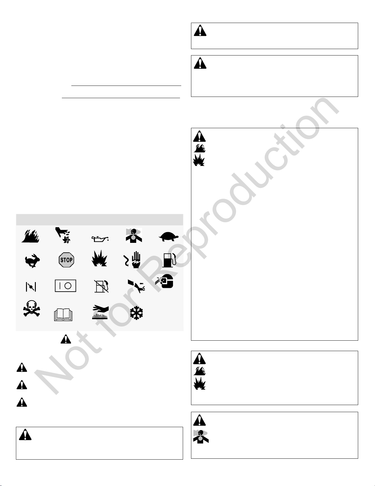
Operator Safety
SAFETY AND CONTROL SYMBOLS
Fire
Fast
Choke
Hazardous
Chemical
The safety alert symbol is used to identify safety information about hazards that can
result in personal injury. A signal word (DANGER, WARNING, or CAUTION) is used with the
alert symbol to indicate the likelihood and the potential severity of injury. In addition, a hazard
symbol may be used to represent the type of hazard.
Moving Parts
Stop
On Off
Read Manual
Oil
Explosion
Fuel Shutoff
Hot Surface
DANGER indicates a hazard which, if not avoided, will result in death or
serious injury.
WARNING indicates a hazard which, if not avoided, could result in death or
serious injury.
CAUTION indicates a hazard which, if not avoided, could result in minor or
moderate injury.
Toxic Fumes
Shock
Kickback
Frostbite
Slow
Fuel
Wear Eye
Protection
WARNING
The engine exhaust from this product contains chemicals known to the State of
California to cause cancer, birth defects, or other reproductive harm.
WARNING
Briggs & Stratton does not approve or authorize the use of these engines on 3-wheel
All Terrain Vehicles (ATVs), motor bikes, fun/recreational go-karts, aircraft products,
or vehicles intended for use in competitive events. Use of these engines in such
applications could result in property damage, serious injury (including paralysis), or
even death.
NOTICE: This engine was shipped from Briggs & Stratton without oil. Before you start
the engine, make sure you add oil according to the instructions in this manual. If you
start the engine without oil, it will be damaged beyond repair and will not be covered
under warranty.
WARNING
Fuel and its vapors are extremely flammable and explosive.
Fire or explosion can cause severe burns or death.
When Adding Fuel
• Turn engine off and let engine cool at least 2 minutes before removing the fuel
cap.
• Fill fuel tank outdoors or in well-ventilated area.
• Do not o verfill fuel tank. To allow for expansion of the fuel, do not fill above the
bottom of the fuel tank neck.
• Keep fuel away from sparks, open flames, pilot lights, heat, and other ignition
sources.
• Check fuel lines, tank, cap, and fittings frequently for cracks or leaks.
Replace if necessary
• If fuel spills, wait until it evaporates before starting engine.
When Starting Engine
• Ensure that spark plug, muffler, fuel cap and air cleaner (if equipped) are in
place and secured.
• Do not crank engine with spark plug removed.
• If engine floods, set choke (if equipped) to OPEN/RUN position, move throttle
(if equipped) to FAST position and crank until engine starts.
When Operating Equipment
• Do not tip engine or equipment at angle which causes fuel to spill.
• Do not choke the carburetor to stop engine.
• Never start or run the engine with the air cleaner assembly (if equipped) or the
air filter (if equipped) removed.
When Changing Oil
• If you drain the oil from the top oil fill tube, the fuel tank must be empty or fuel
can leak out and result in a fire or explosion.
When Transporting Equipment
• Transport with fuel tank EMPTY or with fuel shut-off valve OFF.
When Storing Fuel Or Equipment With Fuel In Tank
• Store away from furnaces, stoves, water heaters or other appliances that have
pilot lights or other ignition sources because they can ignite fuel vapors.
WARNING
Starting engine creates sparking.
Sparking can ignite nearby flammable gases.
Explosion and fire could result.
• If there is natural or LP gas leakage in area, do not start engine.
• Do not use pressurized starting fluids because vapors are flammable.
NOTICE indicates a situation that could result in damage to the product.
WARNING
Certain components in this product and its related accessories contain chemicals
known to the State of California to cause cancer, birth defects, or other reproductive
harm. Wash hands after handling.
4 BRIGGSandSTRATTON.COM
WARNING
Engines give off carbon monoxide, an odorless, colorless, poison gas.
Breathing carbon monoxide can cause nausea, fainting or death.
• Start and run engine outdoors.
• Do not start or run engine in enclosed area, even if doors or windows are open.
WARNING
Not for Reproduction
Rapid retraction of starter cord (kickback) will pull hand and arm
toward engine faster than you can let go.
Broken bones, fractures, bruises or sprains could result.
• When starting engine, pull the starter cord slowly until resistance is felt and then
pull rapidly to avoid kickback.
• Remove all external equipment /engine loads before starting engine.
• Direct-coupled equipment components such as, but not limited to, blades,
impellers, pulleys, sprockets, etc., must be securely attached.
WARNING
Rotating parts can contact or entangle hands, feet, hair, clothing, or
accessories.
Traumatic amputation or severe laceration can result.
• Operate equipment with guards in place.
• Keep hands and feet away from rotating parts.
• Tie up long hair and remove jewelry.
• Do not wear loose-fitting clothing, dangling drawstrings or items that could
become caught.
WARNING
Running engines produce heat. Engine parts, especially muffler,
become extremely hot.
Severe thermal burns can occur on contact.
Combustible debris, such as leaves, grass, brush, etc. can catch fire.
• Allow muffler, engine cylinder and fins to cool before touching.
• Remove accumulated debris from muffler area and cylinder area.
• It is a violation of California Public Resource Code, Section 4442, to use or
operate the engine on any forest-covered, brush-covered, or grass-covered land
unless the exhaust system is equipped with a spark arrester, as defined in
Section 4442, maintained in effective working order. Other states or federal
jurisdictions may have similar laws. Contact the original equipment
manufacturer, retailer, or dealer to obtain a spark arrester designed for the
exhaust system installed on this engine.
WARNING
Unintentional sparking can result in fire or electric shock.
Unintentional start-up can result in entanglement, traumatic
amputation, or laceration.
Fire hazard
Before performing adjustments or repairs:
• Disconnect the spark plug wire and keep it away from the spark plug.
• Disconnect battery at negative terminal (only engines with electric start.)
• Use only correct tools.
• Do not tamper with governor spring, links or other parts to increase engine
speed.
• Replacement parts must be of the same design and installed in the same
position as the original parts. Other parts may not perform as well, may damage
the unit, and may result in injury.
• Do not strike the flywheel with a hammer or hard object because the flywheel
may later shatter during operation.
When testing for spark:
• Use approved spark plug tester.
• Do not check for spark with spark plug removed.
en
5
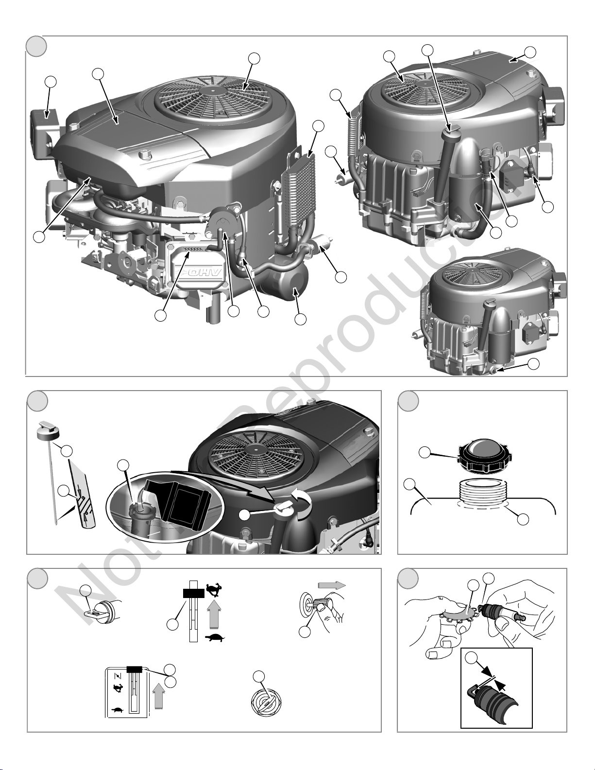
Features and Controls
Not for Reproduction
Compare the illustration
various features and controls.
A. Engine Identification
Model Type Code
B. Spark Plug
C. Air Cleaner
D. Dipstick
E. Oil Drain Plug
F. Rotating Screen
G. Oil Filter
H. Electric Starter
I. Carburetor
J. Fuel Filter (optional)
K. Fuel Pump (optional)
L. Quick Oil Drain (optional)
M. Oil Cooler (optional)
N. Electronic Control Unit (optional)
1
with your engine to familiarize yourself with the location of
Fuel Recommendations
Fuel must meet these requirements:
• Clean, fresh, unleaded gasoline.
• A minimum of 87 octane/87 AKI (91 RON). High altitude use, see below.
• Gasoline with up to 10% ethanol (gasohol) or up to 15% MTBE (methyl tertiary
butyl ether) is acceptable.
CAUTION: Do not use unapproved gasolines, such as E85. Do not mix oil in gasoline or
modify the engine to run on alternate fuels. This will damage the engine components and
void the engine warranty.
To protect the fuel system from gum formation, mix a fuel stabilizer into the fuel. See
Storage. All fuel is not the same. If starting or performance problems occur, change fuel
providers or change brands. This engine is certified to operate on gasoline. The
emissions control system for this engine is EM (Engine Modifications).
High Altitude
At altitudes over 5,000 feet (1524 meters), a minimum 85 octane/85 AKI (89 RON)
gasoline is acceptable. To remain emissions compliant, high altitude adjustment is
required. Operation without this adjustment will cause decreased performance,
increased fuel consumption, and increased emissions. See a Briggs & Stratton
Authorized Dealer for high altitude adjustment information.
Operation of the engine at altitudes below 2,500 feet (762 meters) with the high altitude
kit is not recommended.
Operation
Oil capacity (see the Specifications section)
Oil Recommendations
We recommend the use of Briggs & Stratton Warranty Certified oils for best
performance. Other high-quality detergent oils are acceptable if classified for service SF,
SG, SH, SJ or higher. Do not use special additives.
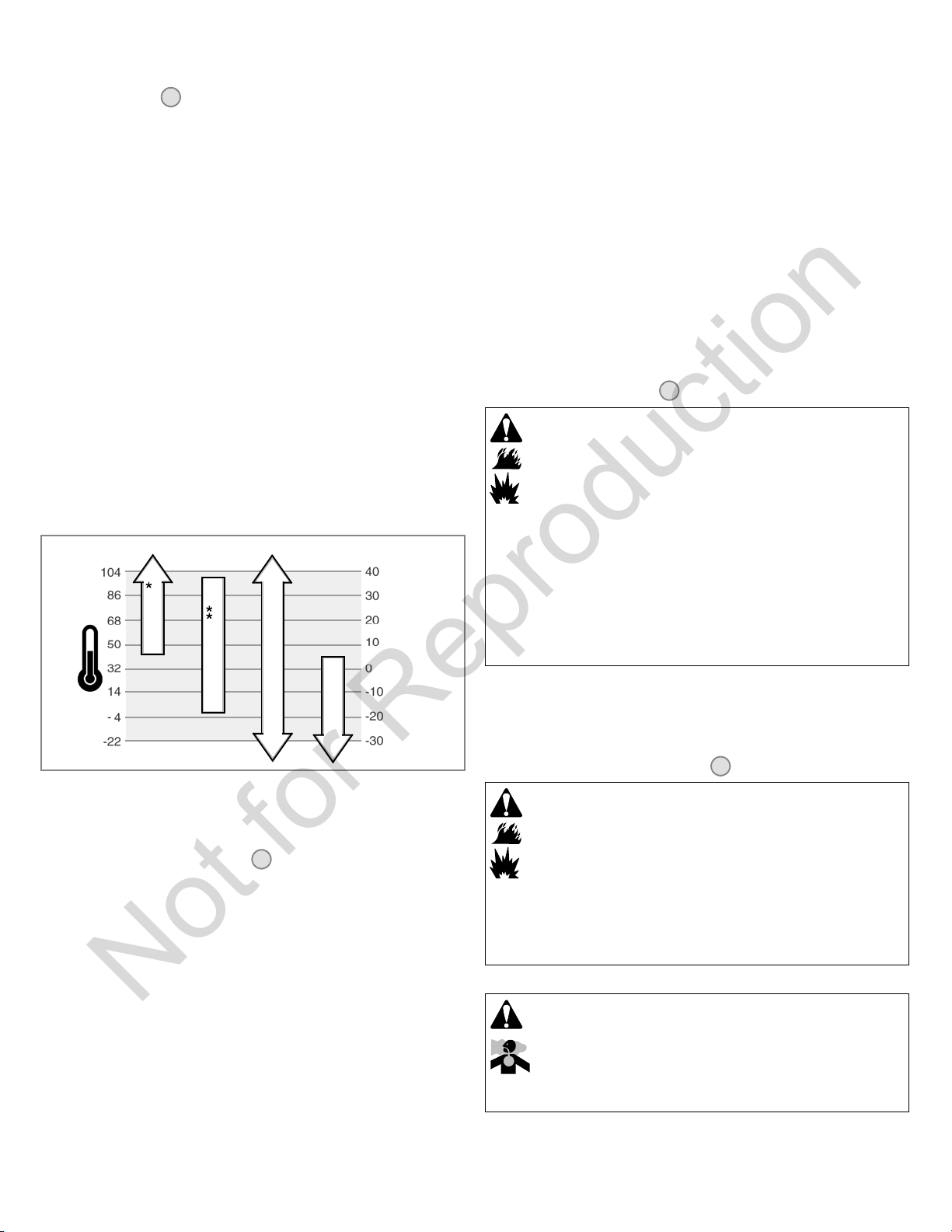
Outdoor temperatures determine the proper oil viscosity for the engine. Use the chart to
select the best viscosity for the outdoor temperature range expected.
°F °C
SAE 30
10W-30
Synthetic 5W-30
* Below 40°F(4°C) the use of SAE 30 will result in hard starting.
** Above 80°F(27°C) the use of 10W-30 may cause increased oil consumption. Check
oil level more frequently.
How To Check/Add Oil - Figure
Before adding or checking the oil
• Place engine level.
• Clean the oil fill area of any debris.
1. Remove the dipstick (A) and wipe with a clean cloth (Figure 2).
2. Insert and tighten the dipstick.
3. Remove the dipstick and check the oil level. It should be at the FULL mark (B)onthe
dipstick.
4. If low, add oil slowly into the engine oil fill (C). Do not overfill. After adding oil, wait
one minute and then recheck the oil level.
Note: Do not add oil at the quick oil drain (L, Figure 1) (if equipped).
5. Replace and tighten the dipstick.
2
5W-30
How To Add Fuel - Figure
WARNING
Fuel and its vapors are extremely flammable and explosive.
Fire or explosion can cause severe burns or death.
When Adding Fuel
• Turn engine off and let engine cool at least 2 minutes before removing the fuel
cap.
• Fill fuel tank outdoors or in well-ventilated area.
• Do not o verfill fuel tank. To allow for expansion of the fuel, do not fill above the
bottom of the fuel tank neck.
• Keep fuel away from sparks, open flames, pilot lights, heat, and other ignition
sources.
• Check fuel lines, tank, cap, and fittings frequently for cracks or leaks.
Replace if necessary
• If fuel spills, wait until it evaporates before starting engine.
1. Clean the fuel cap area of dirt and debris. Remove the fuel cap (A, Figure 3).
2. Fill the fuel tank (B) with fuel. To allow for expansion of the fuel, do not fill above the
bottom of the fuel tank neck (C).
3. Reinstall the fuel cap.
How To Start The Engine - Figure
WARNING
Fuel and its vapors are extremely flammable and explosive.
Fire or explosion can cause severe burns or death.
When Starting Engine
• Ensure that spark plug, muffler, fuel cap and air cleaner (if equipped) are in
place and secured.
• Do not crank engine with spark plug removed.
• If engine floods, set choke (if equipped) to OPEN/RUN position, move throttle
(if equipped) to FAST position and crank until engine starts.
WARNING
Engines give off carbon monoxide, an odorless, colorless, poison gas.
Breathing carbon monoxide can cause nausea, fainting or death.
3
4
Oil Pressure
If the oil pressure is too low, a pressure switch (if equipped) will either stop the engine or
activate a warning device on the equipment. If this occurs, stop the engine and check the
oil level with the dipstick.
If the oil level is below the ADD mark, add oil until it reaches the FULL mark. Start the
engine and check for proper pressure before continuing to operate.
If the oil level is between the ADD and FULL marks, do not start the engine. Contact an
Authorized Briggs & Stratton Dealer to have the oil pressure problem corrected.
6 BRIGGSandSTRATTON.COM
• Start and run engine outdoors.
• Do not start or run engine in enclosed area, even if doors or windows are open.
NOTICE: This engine was shipped from Briggs & Stratton without oil. Before you start
the engine, make sure you add oil according to the instructions in this manual. If you
start the engine without oil, it will be damaged beyond repair and will not be covered
under warranty.
Determine The Starting System
Not for Reproduction
Before starting the engine, you must determine the type of starting system that is on your
engine. Your engine will have one of the following types.
• Electronic Fuel Management System: This features an Electronic Control Unit that
monitors engine and temperature conditions. It does not have a manual choke or a
primer.
• Choke System: This features a choke to be used for starting in cool temperatures.
Some models will have a separate choke control while others will have a
combination choke/throttle control. This type does not have a primer.
To start your engine, follow the instructions for your type of starting system.
Note: Some engines and equipment have remote controls. See the equipment manual
for location and operation of remote controls.
Electronic Fuel Management System - Figure
1. Check the oil level. See the How To Check/Add Oil section.
2. Make sure equipment drive controls, if equipped, are disengaged.
3. Turn the fuel shut-off valve (A), if equipped, to the on position (Figure 4).
4. Move the throttle control (B)tothefast
position.
5. Turn the electric start switch (D) to the on/start position (Figure 4).
NOTE: If the engine does not start after repeated attempts, go to
BRIGGSandSTRATTON.COM or call 1-800-233-3723 (in USA).
NOTICE: To extend the life of the starter, use short starting cycles (five seconds
maximum). Wait one minute between starting cycles.
position. Operate the engine in the fast
4
WARNING
Unintentional sparking can result in fire or electric shock.
Unintentional start-up can result in entanglement, traumatic
amputation, or laceration.
Fire hazard
Before performing adjustments or repairs:
• Disconnect the spark plug wire and keep it away from the spark plug.
• Disconnect battery at negative terminal (only engines with electric start.)
• Use only correct tools.
• Do not tamper with governor spring, links or other parts to increase engine
speed.
• Replacement parts must be of the same design and installed in the same
position as the original parts. Other parts may not perform as well, may damage
the unit, and may result in injury.
• Do not strike the flywheel with a hammer or hard object because the flywheel
may later shatter during operation.
When testing for spark:
• Use approved spark plug tester.
• Do not check for spark with spark plug removed.
Choke System - Figure
1. Check the oil level. See the How To Check/Add Oil section.
2. Make sure equipment drive controls, if equipped, are disengaged.
3. Turn the fuel shut-off valve (A), if equipped, to the on position (Figure 4).
4. Move the throttle control (B)tothefast
position.
5. Move the choke control (C), or the combination choke/throttle lever, to the choke
position.
Note: Choke is usually unnecessary when restarting a warm engine.
6. Turn the electric start switch (D) to the on/start position (Figure 4).
NOTE: If the engine does not start after repeated attempts, go to
BRIGGSandSTRATTON.COM or call 1-800-233-3723 (in USA).
NOTICE: To extend the life of the starter, use short starting cycles (five seconds
maximum). Wait one minute between starting cycles.
7. As the engine warms up, move the choke control ( C)totherun
How To Stop The Engine - Figure
4
position. Operate the engine in the fast
position.
4
WARNING
Fuel and its vapors are extremely flammable and explosive.
Fire or explosion can cause severe burns or death.
• Do not choke the carburetor to stop engine.
1. Move the throttle control to the slow position. Turn the key switch (D) to the off
position (Figure 4). Remove the key and keep in a safe place out of the reach of
children.
2. After t he engine stops, turn the fuel shut-off valve (A), if equipped, to the closed
position.
Maintenance
We recommend that you see any Briggs & Stratton Authorized Dealer for all
maintenance and service of the engine and engine parts.
NOTICE: All the components used to build this engine must remain in place for proper
operation.
Emissions Control
Maintenance, replacement, or repair of the emissions control devices and systems
may be performed by any non-road engine repair establishment or individual.
However, to obtain “no charge” emissions control service, the work must be performed
by a factory authorized dealer. See the Emissions Warranty.
en
Maintenance Chart
First 5 Hours
• Change oil
Every8HoursorDaily
• Check engine oil level
• Clean area around muffler and controls
• Clean finger guard/rotating screen
Every 25 Hours or Annually
• Clean air filter *
• Clean pre-cleaner *
Every 50 Hours or Annually
• Change engine oil
• Replace oil filter (if equipped)
• Check muffler and spark arrester
Annually
• Replace air filter
• Replace pre-cleaner
• Replace spark plugs
• Clean air cooling system *
• Replace fuel filter
• Check valve clearance **
* In dusty conditions or when airborne debris is present, clean more often.
** Not required unless engine performance problems are noted.
Electronic Fuel Management System
The Electronic Fuel Management System monitors engine temperature, engine speed,
and battery voltage to adjust the choke during engine starting and warm up. There are no
adjustments on the system. If starting or operation problems occur, contact an
Authorized Briggs & Stratton Dealer.
NOTICE: Make sure to follow the steps below or the Electronic Fuel Management
System could be damaged.
• Never start the engine if the battery cables are loose.
• Turn the key to the off position before disconnecting, removing and/or installing the
battery.
• Never use a battery charger to start the engine.
• Never disconnect the battery cables while the engine is running.
• When connecting the battery cables, first connect the positive (+) cable and then
connect the negative (--) cable to the battery.
• When charging the battery, turn the ignition switch to the off position and disconnect
the negative (--) battery cable from the battery.
• Do not spray water directly on the Electronic Control Unit.
7
Carburetor Adjustment
Not for Reproduction
Never make adjustments to the carburetor. The carburetor was set at the factory to
operate efficiently under most conditions. However, if adjustments are required, see a
Briggs & Stratton Authorized Dealer for service.
NOTICE: The manufacturer of the equipment on which this engine is installed specifies
the top speed at which the engine will be operated. Do not exceed this speed.
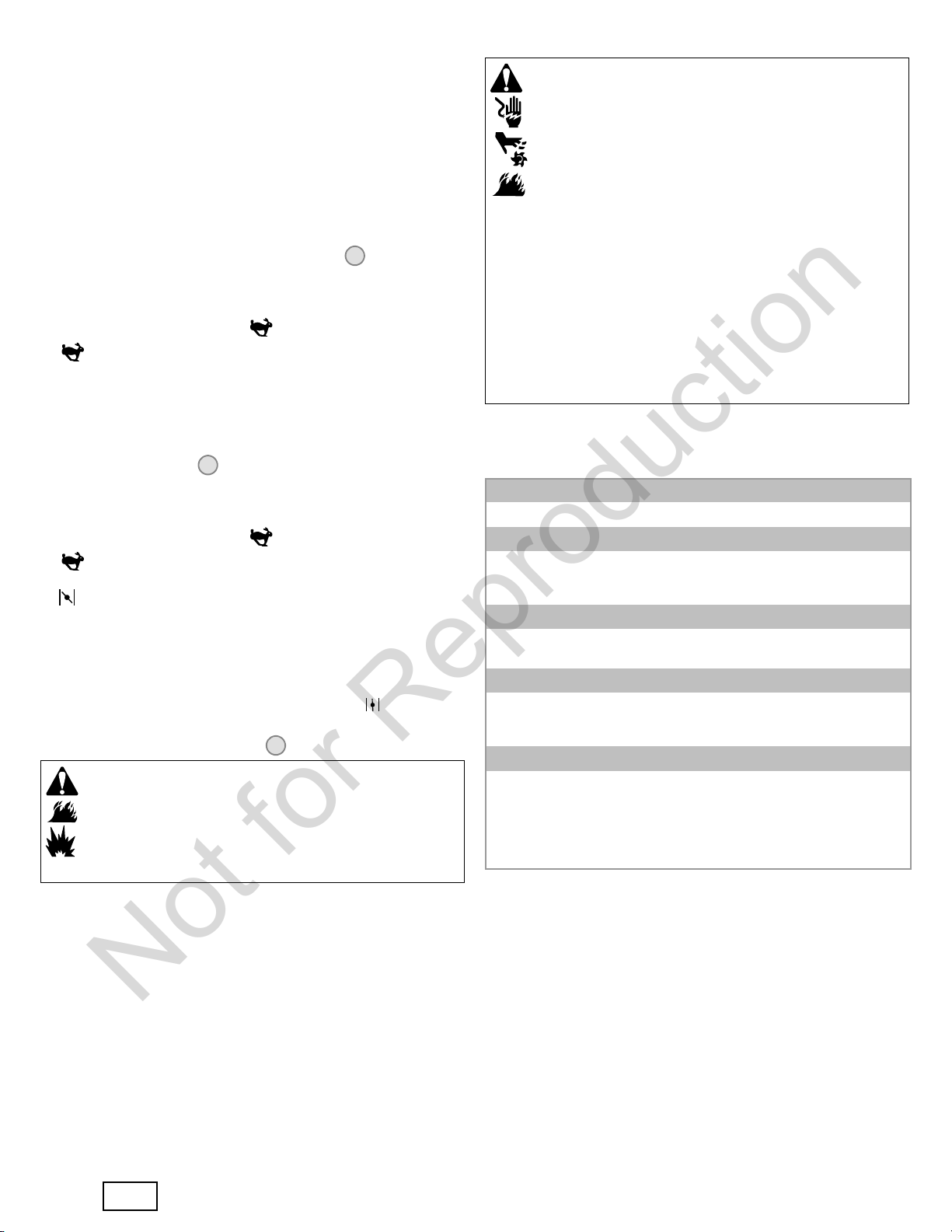
How To Replace The Spark Plug - Figure
Check the gap (A, Figure 5) with a wire gauge (B). If necessary, reset the gap. Install
and tighten the spark plug to the recommended torque. For gap setting or torque, see the
Specifications section.
Note: In some areas, local law requires using a resistor spark plug to suppress ignition
signals. If this engine was originally equipped with a resistor spark plug, use the same
type for replacement.
5
6. Start and run t he engine. As the engine warms up, check for oil leaks.
7. Stop the engine and check the oil level. It should be at the FULL mark on the
dipstick.
Add Oil
• Place engine level.
• Clean the oil fill area of any debris.
• See the Specifications section for oil capacity.
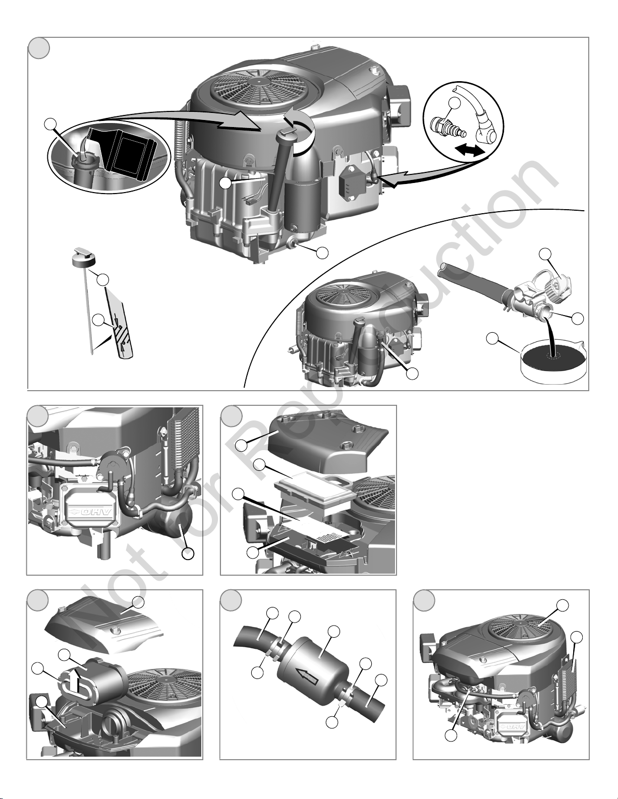
1. Remove the dipstick (D) and wipe with a clean cloth (Figure 6).
2. Pour the oil slowly into the engine oil fill (E). Do not overfill. After adding oil, wait
one minute and then check the oil level.
3. Install and tighten the dipstick.
4. Remove the dipstick and check the oil level. It should be at the FULL mark (F)onthe
dipstick.
5. Install and tighten the dipstick.
Inspect Muffler And Spark Arrester
WARNING
Running engines produce heat. Engine parts, especially muffler,
become extremely hot.
Severe thermal burns can occur on contact.
Combustible debris, such as leaves, grass, brush, etc. can catch fire.
• Allow muffler, engine cylinder and fins to cool before touching.
• Remove accumulated debris from muffler area and cylinder area.
• It is a violation of California Public Resource Code, Section 4442, to use or
operate the engine on any forest-covered, brush-covered, or grass-covered land
unless the exhaust system is equipped with a spark arrester, as defined in
Section 4442, maintained in effective working order. Other states or federal
jurisdictions may have similar laws. Contact the original equipment
manufacturer, retailer, or dealer to obtain a spark arrester designed for the
exhaust system installed on this engine.
Exhaust system parts are installed by the equipment manufacturer. For specific
maintenance and replacement information, contact the equipment manufacturer.
Remove accumulated debris from muffler area and cylinder area. Inspect the muffler for
cracks, corrosion, or other damage. Remove the spark arrester, if equipped, and inspect
for damage or carbon blockage. If damage is found, install replacement parts before
operating.
WARNING: Replacement parts must be of the same design and installed
in the same position as the original parts. Other parts may not perform as well, may
damage the unit, and may result in injury.
How To Change The Oil - Figure
Used oil is a hazardous waste product and must be disposed of properly. Do not discard
with household waste. Check with your local authorities, service center, or dealer for safe
disposal/recycling facilities.
6 7
Remove Oil
1. With engine off but still warm, disconnect the spark plug wire (A) and keep it away
from the spark plug (Figure 6).
2. Remove the dipstick (D).
Standard Oil Drain Plug
1. Remove the oil drain plug (B). Drain the oil into an approved container.
Note: Any of the oil drain plugs shown below may be installed in t he engine.
How To Service The Air Filter - Figure
8 9
WARNING
Fuel and its vapors are extremely flammable and explosive.
Fire or explosion can cause severe burns or death.
• Never start or run the engine with the air cleaner assembly (if equipped) or the
air filter (if equipped) removed.
NOTICE: Do not use pressurized air or solvents to clean the filter. Pressurized air can
damage the filter and solvents will dissolve the filter.
The air filter system uses either a flat or oval cartridge. Some models are also equipped
with a pre-cleaner that can be washed and reused.
Flat Air Filter
1. Remove the cover (A, Figure 8).
2. Remove the filter (C) and the pre-cleaner (B).
3. To loosen debris, gently tap the filter on a hard surface. If t he filter is excessively
dirty, replace with a new filter.
4. Wash the pre-cleaner in liquid detergent and water. Then allow it to thoroughly air
dry. Do not oil the pre-cleaner.
5. Assemble the dry pre-cleaner and the filter into the engine base (D).
6. Install the cover.
Oval Air Filter
1. Remove the cover (A, Figure 9).
2. To remove the filter (B), lift the end of the filter.
3. Remove the pre-cleaner (C), if equipped, from the filter.
4. To loosen debris, gently tap the filter on a hard surface. If t he filter is excessively
dirty, replace with a new filter.
5. Wash the pre-cleaner in liquid detergent and water. Then allow it to thoroughly air
dry. Do not oil the pre-cleaner.
6. Assemble the dry pre-cleaner to the filter.
7. Install the filter into the engine base (D) and push down until the f ilter snaps in place.
8. Install the cover.
How To Replace The Fuel Filter - Figure
10
WARNING
Fuel and its vapors are extremely flammable and explosive.
Fire or explosion can cause severe burns or death.
2. After the oil has drained, install and tighten the oil drain plug.
Optional Quick Oil Drain
1. Disconnect the oil drain hose (G, Figure 6) from the side of the engine.
2. Turn and remove the oil drain cap (H). Carefully lower the quick oil drain (I)intoan
approved container (J).
3. After the oil has drained, install the oil drain cap. Attach the oil drain hose to the side
of the engine.
Change The Oil Filter (if equipped)
For replacement intervals, see the Maintenance chart.
1. Drain the oil from the engine. See Remove Oil section.
2. Remove the oil filter (C) and dispose of properly. See Figure 7.
3. Before you install the new oil filter, lightly lubricate the oil filter gasket with fresh,
clean oil.
4. Install t he oil filter by hand until the gasket contacts the oil filter adapter, then tighten
theoilfilter1/2to3/4turns.
5. Add oil. See Add Oil section.
8
• Keep fuel away from sparks, open flames, pilot lights, heat, and other ignition
sources.
• Check fuel lines, tank, cap, and fittings frequently for cracks or leaks.
Replace if necessary.
• Before replacing the fuel filter, drain the fuel tank or close the fuel shut-off valve.
• Replacement parts must be the same and installed in the same position as the
original parts.
• If fuel spills, wait until it evaporates before starting engine.
1. Before replacing the fuel filter (A, Figure 10), if equipped, drain the fuel tank or close
the fuel shut-off valve. Otherwise, fuel can leak out and cause a fire or explosion.
2. Use pliers to squeeze tabs (B) on the clamps (C), then slide the clamps away from
the fuel filter. Twist and pull the fuel lines (D) off of the fuel filter.
3. Check the fuel lines for cracks or leaks. Replace if necessary.
4. Replace the fuel filter with an original equipment replacement filter.
5. Secure the fuel lines with the clamps as shown.
BRIGGSandSTRATTON.COM
How To Clean The Air Cooling System - Figure
Not for Reproduction
11
WARNING
Running engines produce heat. Engine parts, especially muffler,
become extremely hot.
Severe thermal burns can occur on contact.
Combustible debris, such as leaves, grass, brush, etc. can catch fire.
• Allow muffler, engine cylinder and fins to cool before touching.
• Remove accumulated debris from muffler area and cylinder area.
NOTICE: Do not use water to clean the engine. Water could contaminate the fuel
system. Use a brush or dry cloth to clean the engine.
This is an air cooled engine. Dirt or debris can restrict air flow and cause the engine to
overheat, resulting in poor performance and reduced engine life.
Use a brush or dry cloth to remove debris from the finger guard/rotating screen (A).
Keep linkage, springs and controls (B) clean. Keep the area around and behind the
muffler free of any combustible debris (Figure 11). Make sure the oil cooler fins (C)are
free of dirt and debris.
Storage
WARNING
Fuel and its vapors are extremely flammable and explosive.
Fire or explosion can cause severe burns or death.
When Storing Fuel Or Equipment With Fuel In Tank
• Store away from furnaces, stoves, water heaters or other appliances that have
pilot lights or other ignition sources because they can ignite fuel vapors.
Fuel System
Fuel can become stale when stored over 30 days. Stale fuel causes acid and gum
deposits to form in the fuel system or on essential carburetor parts. To keep fuel fresh,
use Briggs & Stratton FRESH START®fuel stabilizer, available as a liquid additive or a
drip concentrate cartridge.
There is no need to drain gasoline from the engine if a fuel stabilizer is added according
to instructions. Run the engine for 2 minutes to circulate the stabilizer throughout the fuel
system. The engine and fuel can then be stored up to 24 months.
If gasoline in the engine has not been treated with a fuel stabilizer, it must be drained into
an approved container. Run the engine until it stops from lack of fuel. The use of a fuel
stabilizer in the storage container is recommended to maintain freshness.
Engine Oil
While the engine is still warm, change the engine oil. See the How To Change The Oil
section.
Troubleshooting
Need Assistance? Go to BRIGGSandSTRATTON.COM or call 1-800-233-3723.
Specifications
Engine Specifications
Model 400000
Displacement 40.03 ci (656 cc)
Bore 2.970 in (75.43 mm)
Stroke 2.890 in (73.41 mm)
Oil Capacity 62 -- 64 oz (1.8 -- 1.9 L)
Engine Specifications
Model 440000
Displacement 44.18 ci (724 cc)
Bore 3.120 in (79.24 mm)
Stroke 2.890 in (73.41 mm)
Oil Capacity 62 -- 64 oz (1.8 -- 1.9 L)
Engine Specifications
Model 490000
Displacement 49.42 ci (810 cc)
Bore 3.300 in (83.81 mm)
Stroke 2.890 in (73.41 mm)
Oil Capacity 66 -- 68 oz (1.9 -- 2.0 L)
Tune-up Specifications *
Model 400000, 440000, 490000
Spark Plug Gap 0.030 in (0.76 mm)
Spark Plug Torque 180 lb-in (20 Nm)
Armature Air Gap 0.008 - 0.012 in (0.20 - 0.30 mm)
Intake Valve Clearance 0.004 - 0.006 in (0.10 - 0.15 mm)
Exhaust Valve Clearance 0.004 - 0.006 in (0.10 - 0.15 mm)
* Engine power will decrease 3.5% for each 1,000 feet (300 meters) above sea level and
1% for each 10° F(5.6° C) above 77° F(25° C). The engine will operate satisfactorily at
an angle up to 15°. Refer to the equipment operator’s manual for safe allowable
operating limits on slopes.
Common Service Parts n
Service Part Part Number
Air Filter, Flat 499486
Air Filter Pre-cleaner, Flat 273638
Air Filter, Oval 792105
Air Filter Pre-cleaner, Oval 792303
Oil -- SAE 30 100028
Oil Filter 492932
Fuel Filter 691035
Fuel Additive 5041, 5058
Resistor Spark Plug 491055
Long Life Platinum Spark Plug 5066
Spark Plug Wrench 19374
Spark Tester 19368
n We recommend that you see any Briggs & Stratton Authorized Dealer for all
maintenance and service of the engine and engine parts.
en
9
 Loading...