


Braun UVL 603B, UVL 855RH, UVL 604XC, UVL 603E, UVL 603A User Manual
...Braun UVL® Under Vehicle Wheelchair Lifts
Owner's Manual for:
UVL® Series
Under Vehicle Wheelchair Lifts
|
|
||
|
|
|
|
|
UVL |
||
|
Including Models: |
|
|
• UVL603A |
• UVL604XC |
|
|
• UVL603B |
• UVL604XD |
Note to Dealer: |
|
• UVL603E |
• UVL855R |
Provide this manual |
|
• UVL604XA |
• UVL855RH |
to the consumer. |
|
|
|||
• UVL604XB |
See inside cover for |
|
warranty/registration |
||
|
||
and Special Order |
information. |
|
|
||
UVL® Series Lift Models |
|
®
"Providing Access to the World"
International Corporate Hdqrs: P.O. Box 310 |
Winamac, IN 46996 |
USA |
|
1-800-THE LIFT |
(219) 946-6153 |
FAX: (219) 946-4670 |
|
WARNING |
|
|
Owner's |
|
|
Manual |
|
|
Read manual |
|
|
before operating |
|
|
lift. Failure to do |
Braun |
|
so may result in |
||
serious bodily |
||
injury and/or |
||
property damage. |
||
®UVL |
||
Keep manual in |
||
lift vehicle. |
||
|
||
|
Series |
89001 |
September 1998 |
Patent #4,958,979 |
Congratulations
We at The Braun Corporation wish to express our fullest appreciation
on your new purchase. With you in mind, our skilled craftsmen have designed and assembled the finest lift available.
This manual includes safety precautions, lift operating instructions, manual operating instructions, and instructions for maintenance and lubrication procedures.
Your lift is built for dependability, and will bring you years of pleasure and independence, as long as maintenance is performed regularly
and the lift is operated by an instructed person.
Sincerely,
THE BRAUN CORPORATION
Ralph W. Braun
Chief Executive Officer
Warranty/Registration Instructions
Immediately upon receiving:
Examine the unit for any damage. Notify the carrier at once with any claims.
Two warranty/registration cards (shown right) are protected in a clear envelope and attached to the lift protective shipping wrap. The sales representative must process one of the cards. The consumer must fill out the other card and mail it to The Braun Corporation. The warranty is provided on the back cover of this manual.
OWNER'S WARRANTY REGISTRATION
PURCHASED FROM
OWNER
DATE INSTALLED
NAME
ADDRESS
CITY
TELEPHONE |
|
STATE |
|
ZIP |
TO VALIDATE WARRANTY
REGISTRATION CARDS MUST BE RETURNED TO THE BRAUN CORPORATION.
Sample Warranty/Registration Card
The Braun Serial No./Series No. identification tag (shown below) is located on the left platform side plate (outboard end). This I.D. tag contains the product identification information provided on the Warranty/Registration card. Record the information in the space provided. This information must be provided when filing a warranty claim or ordering parts.
Lift Model No. Lift Serial No.
THE BRAUN CORPORATION |
Model No. |
||||||||
P.O. BOX 310 WINAMAC IN |
46996 |
|
|||||||
219-946-6153 |
|
|
|
Series No. |
|||||
MODEL |
|
|
|||||||
|
UVL603A |
|
|
|
|
|
|
||
SERIAL NUMBER |
|
DOM |
Serial No. |
||||||
|
OD |
. |
2632 |
. . |
|
0597 |
|
||
|
|
|
|||||||
|
PATENT 4,958,979 |
|
|
|
|||||
Date of Manufacture
Lift Series No. |
Date of Manufacture |
Sample Serial No./Series No. Identification Tag
RETAIN THIS INFORMATION FOR FUTURE USE. YOU MUST HAVE THIS INFORMATION WHEN FILING A WARRANTY CLAIM OR ORDERING PARTS!

Table of Contents
Lift Terminology |
|
UVL® 600 Series Lift Terminology Illustration ............ |
2 |
UVL® 600X Series Lift Terminology Illustration .......... |
2 |
UVL® 850 Series Lift Terminology Illustration ............. |
3 |
Lift Terminology Description |
|
General ................................................................ |
3 |
Direction .............................................................. |
3 |
Lift Components .................................................. |
4 |
Lift Actions and Functions ................................... |
4 |
Lift Operation Safety |
|
Safety Symbols .......................................................... |
5 |
Lift Operation Safety Precautions ........................... |
5-7 |
Pre-Lift Operation Notes |
|
General Safety ........................................................... |
7 |
Outboard Roll Stop ................................................ |
7, 8 |
Bridge Plate (Inboard Roll Stop) ............................ |
8, 9 |
Handrails .................................................................... |
9 |
Passenger Orientation ............................................... |
9 |
Vehicle (Floor Level) Loading/Unloading ................... |
9 |
Wheelchair-equipped Occupant Seat Belts ............... |
9 |
Operation Procedure Review ................................... |
10 |
Preventive Maintenance ........................................... |
10 |
Cold Climate Recommendations .............................. |
10 |
Lift Operating Instructions |
|
Before Lift Operation ................................................. |
10 |
Vehicle Lift Door(s) ................................................... |
10 |
Lift Control Switches ................................................. |
11 |
Control Switch Functions .......................................... |
11 |
Manual Bridge Plate Operating Instructions |
......12 |
Dual Stationary Handrail Instructions ................. |
13 |
Dual Manual Fold “P” Handrail Instructions ...... |
13 |
Dual Manual Fold “U” Handrail (with Shield) |
|
Instructions ........................................................... |
14 |
Manual Operating Instructions |
|
Cable-Activated Platform Manual Release |
|
System Introduction ............................................ |
15, 16 |
Platform Carriage Assembly Drive Chain |
|
Re-engagement Procedure ...................................... |
16 |
To Manually Move Platform Out (Extend) From |
|
Stow Position ............................................................ |
16 |
To Manually Raise Platform To Floor Level .............. |
17 |
To Manually Lower Platform To Ground Level ......... |
18 |
To Manually Move Platform In (Retract) To |
|
Stow Position ............................................................ |
19 |
Outboard Roll Stop Manual Operation |
|
Introduction ........................................................ |
19 |
To Manually Lower Outboard Roll Stop ............. |
20 |
To Reengage Outboard Roll Stop ..................... |
20 |
Maintenance and Lubrication ............................. |
21 |
Decals ................................................................... |
22 |
Warranty/Registration Policy .............................. |
23 |
Return Authorization Procedure ........................ |
23 |
Page 1

Lift Terminology
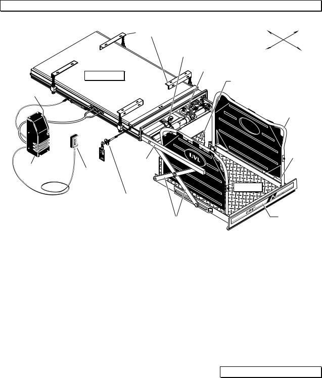
UVL®600 Series Lift Terminology Illustration
|
|
Lift Mounting |
Inboard |
Right |
|
|
Brackets (4) |
|
|
|
|
Chain Drive |
|
|
|
|
Motor |
Left |
Outboard |
|
|
|
Hydraulic |
|
Hand |
Lift Housing |
Cylinder |
|
|
|
|
|||
Pump |
|
|
|
|
(inside |
|
|
Lifting Arms |
|
cover) |
|
|
|
|
|
|
|
|
|
|
|
|
|
Rolling |
|
|
|
|
Horizontal |
|
|
|
|
Arms |
|
|
|
|
Roll Stop |
|
|
|
|
Actuator |
|
WA |
|
|
|
|
RNING |
|
|
|
|
Donot |
|
|
|
|
remove! |
|
Platform |
|
Pump |
|
|
|
|
Hand-Held |
|
|
|
|
Module |
|
|
|
|
|
Attendant's |
Platform Cable- |
|
|
|
Control Box |
|
|
|
|
activated Manual |
|
|
|
|
|
|
|
|
|
|
Release System |
|
Outboard |
|
|
|
|
|
|
|
|
|
Roll Stop |
UVL®600X Series Lift Terminology Illustration
Lift Mounting |
Inboard |
Right |
Brackets (4) |
|
|
Chain Drive Motor |
|
|
|
(inside cover) |
|
|
Left |
Outboard |
|
Hydraulic |
|
|
Cylinder |
|
Lift Housing |
Bridge Plate |
Manual |
|
(Inboard Roll Stop) |
Folding “P” |
|
Rolling |
Handrails |
|
|
|
|
Horizontal |
|
|
Arms |
|
Hand Pump (inside cover)
WARNING |
|
Donot |
remove! |
Pump |
Hand-Held |
|
|
Module |
|
||
Attendant's |
Platform Cable- |
||
|
|||
|
Control Box |
||
|
activated Manual |
||
|
|
||
|
|
Release System |
Lifting Arms
Roll Stop 
Actuator
Platform |
Outboard
Roll Stop
Page 2
Lift Terminology
UVL®850 Series Lift Terminology Illustration
Lift Mounting |
Inboard |
Right |
Brackets (4) |
|
|
Chain Drive |
|
|
Motor |
Left |
Outboard |
Hydraulic |
|
|
Cylinder |
|
|
Lift Housing |
Inboard Roll Stop |
|
Hand Pump |
|
|
(Bridge Plate) |
|
|
(inside cover) |
|
|
|
|
|
|
|
Manual Fold |
|
|
“U” Handrails |
|
|
with Shields |
|
WA |
Roll Stop |
|
RNING |
Actuator |
|
|
|
|
|
Rolling |
Pump |
Hand-Held |
Horizontal |
Module |
Arms |
|
|
Attendant's |
|
|
Control Box |
Platform |
|
Platform Cable-activated |
|
|
Manual Release System |
|
Lifting Arms |
Outboard |
|
Roll Stop |
||
|
Lift Terminology Description
The UVL Lift Series includes three classifications of lifts (UVL600 Series, UVL600X Series and UVL850 Series). Refer to the illustrations on pages 2 and 3 for the visual differences in lift configurations and identification of lift components.
UVL600 Series lift models are consumer oriented (intended for operation by the wheelchair passenger). UVL600X lift models are commercial oriented and ADA compliant (intended for operation by an attendant). UVL600 Series and UVL600X lift platforms raise and lower with an “arcing” motion. UVL600 Series lifts offer a variety of options including bridge plates (inboard roll stops) and handrails.
UVL850 Series lifts are commer-
cial oriented, ADA compliant and designed for use in vehicles with increased floor-to-ground requirements such as buses, trailers and motor homes. UVL850 lift platforms travel vertically straight up and down (no “arcing” motion).
UVL lift models provide fully automatic operation of all lift functions as well as optional automatic door operators (if so equipped). Basic lift operation procedures are identical for all UVL Series lift models. The operating instructions contained in this manual address the lift control switches and the corresponding lift functions. Separate instructions are provided for operation of manual bridge plates (inboard roll stops) and handrails (stationary and folding) that may
be present on your particular lift model. Instructions are provided for manual operation of the lift in event of power or equipment failure.
Terminology: Become familiar with the terminology that will be used throughout this manual.
Become familiar with the identification of lift components and their functions.
Direction:
The terms "left," "right," "inboard," and "outboard" will be used throughout this manual to indicate direction (as viewed from outside the vehicle looking directly at the lift outboard roll stop). Refer to the Lift Terminology Illustrations for clarification of direction terms.
Page 3

Lift Terminology
Lift Components:
Refer to the Lift Terminology Illustrations on pages 2 and 3.
Pump Module: The remote mounted pump module consists of the main hydraulic pump, the manual hand pump, the logic control board and other electrical components that power the lift electric/hydraulic systems.
Hand-held Switch Control Box:
The standard hand-held control switchbox is connected to the pump module. The control box is equipped with four push-button switches, (UP, DOWN, STOW, and DOOR CLOSE). The switches activate the fully automatic lift functions as well as optional automatic door operators (if so equipped). Details regarding the control switches and their functions are provided in the Lift Operation section (page 11).
Lift Housing: The lift housing is the metal structure (casing) mounted under the vehicle which contains and protects the platform carriage assembly. The housing contains all lift components
except the power (pump) module when the lift is in the stowed position.
Platform Carriage Assembly:
The platform carriage assembly includes the platform assembly, the lifting arms, the rolling horizontal arms that carry the platform assembly in and out of the housing and the electrical/ hydraulic drive components that power the lift.
Platform Assembly: The lift platform assembly consists of the flat aluminum plate with raised diamond embossing upon which the wheelchair is positioned, the outboard roll stop, the inboard roll stop (if so equipped) and optional handrails (if so equipped).
Outboard Roll Stop: The outboard roll stop is the automatic electric actuator-activated outer barrier that provides a ramp for wheelchair loading and unloading at ground level. Photos and further details regarding the outboard roll stop operation are provided in the Pre-Lift Operation Notes section (pages 7 and 8).
Bridge Plate (Inboard Roll Stop): UVL lift models are equipped with an automatic or manually operated bridge plate (except model UVL603A). The bridge plate bridges the gap between the lift platform and the vehicle floor. Bridge plates also serve as inboard roll stops.
Automatic bridge plates are fullyautomatic in operation and are activated by the lift control switches (no attendant required). Manual bridge plates must be operated by an attendant. Further details and instructions for operation of manual bridge plates are provided on page 12 of this manual.
Platform Cable-activated Manual Release System: A cable-activated manual release system releases the platform carriage assembly drive chain to allow the platform carriage assembly to be manually moved out (extended) or moved in (retracted), should it be necessary. Complete details and operating procedures are provided on pages 15-19.
Lift Actions and Functions:
Extend: Extend is the action of the platfom carriage assembly moving (rolling) out of the lift housing.
Retract: Retract is the action of the platfom carriage assembly moving (rolling) into the lift housing.
Deploy: Lift deployment is the action of the lift platform carriage assembly extending (moving outward) from the housing and lowering to ground level when the
DOWN switch is activated or raising to floor level when the UP switch is activated.
Stow: Stow is the action of the lift platform carriage assembly retracting (moving inward) into the carriage assembly housing. During the stow function, the platform will automatically raise or lower to stow level before retracting into the housing.
Stow Level: Stow level is the height that the platfom carriage
assembly moves in and moves out of the lift housing.
Floor Level: Floor level is the height that the platfom carriage assembly raises to in order for the wheelchair passenger to enter and exit the vehicle.
Note: Further details regarding lift control switches and the corresponding lift functions are provided in the Lift Operating Instructions on pages 10 and 11.
Page 4
Lift Operation Safety
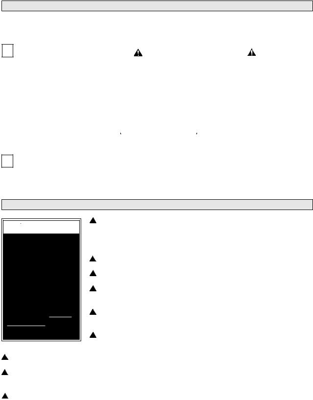
Safety Symbols
SAFETY FIRST! Know That....
A All information contained in this manual and
supplements (if included), is provided for your safety. Familiarity with proper operation instructions as well as proper installation and maintenance procedures are necessary to ensure safe, troublefree operation. Safety precautions are provided to identify potentially hazardous situations and provide instruction on how to avoid them.
B |
|
|
|
|
|
C |
|
|
|
|
|
|
WARNING |
|
|
|
|
CAUTION |
|
||
|
|
|
|
|
|
|
|
|
|
|
|
|
|
This symbol indicates |
|
|
|
|
|
This symbol indicates |
|
|
|
|
important safety |
|
|
|
|
|
important information |
|
|
|
|
information regarding |
|
|
|
|
|
regarding how to |
|
|
|
|
a potentially hazard- |
|
|
|
|
|
avoid a hazardous |
|
|
|
|
ous situation that |
|
|
|
|
|
situation that could |
|
|
|
|
could result in serious |
|
|
|
|
|
result in minor per- |
|
|
|
|
bodily injury and/or |
|
|
|
|
|
sonal injury or prop- |
|
|
|
|
property damage. |
|
|
|
|
|
erty damage. |
|
|
|
|
|
|
|
|
|
|
|
|
|
|
|
|
|
|
|
|
|
|
|
D Note: Additional information provided to help clarify or detail a specific subject.
These symbols will appear throughout this manual as well as on the labels posted on your lift. Recognize the seriousness of this information.
Lift Operation Safety Precautions
 WARNING
If the lift operating instructions, manual operating instructions and/or lift operation safety precautions are not fully understood, contact The Braun Corporation immediately. Failure to do so may result in serious bodily injury and/or property damage.
 WARNING Read manual and supplement(s) before operating lift. Read and become familiar with all safety precautions, pre-lift operation notes, operating instructions and manual operating instructions before operating the lift.
 WARNING Load and unload on level surface only.
 WARNING Engage vehicle parking brake before operating lift.
 WARNING Provide adequate clearance outside the vehicle to accommodate the lift before opening lift door(s) or operating lift.
 WARNING Inspect lift before operation. Do not operate lift if you suspect lift damage, wear or any abnormal condition.
 WARNING Keep operator and bystanders clear of area in which the lift operates.
 WARNING Stand clear of doors, stepwell and platform during lift operation.
 WARNING Do not jack the vehicle by the bumper or frame, this could cause damage to the drive shaft and/or wheelchair lift.
 WARNING Whenever a wheelchair passenger (or standee) is on the platform, the:
•Passenger must be positioned in center of platform
•Wheelchair brakes must be locked
•Roll stop must be up (vertical)
•Passenger should grip both handrails if able (if so equipped).
Page 5

Lift Operation Safety
Lift Operation Safety Precautions (continued)
 WARNING Load and unload clear of vehicular traffic.
 WARNING Do not overload or abuse. The load rating applies to both the raising and lowering functions - continuous lifting capacity is 750 lbs.
 WARNING Do not operate or board the lift if you or your lift operator are intoxicated.
 WARNING Do not raise front wheelchair wheels (pull wheelie) when loading (boarding) the platform.
 WARNING Open lift door(s) fully and secure before operating lift.
 WARNING Position and secure (buckle, engage, fasten, etc.) the wheelchair-equipped occupant seat belt (torso restraint) before loading onto the wheelchair lift platform.
 WARNING Fold manual-fold handrails down before stowing lift.
 WARNING Lift occupant must keep hands, arms and all other body parts within the lift occupant area and clear of moving parts.
 WARNING Platform must be positioned at floor level when loading or unloading in and out of vehicle.
 WARNING Do not use the outboard roll stop as a barrier (brake). Stop and brake wheelchair when fully loaded on the platform (manually stop and brake manual wheelchairs — stop powered wheelchairs with the wheelchair controls).
 WARNING Turn powered (electric) wheelchairs off when on lift platform.
 WARNING Press the DOWN switch until the entire platform rests on ground level (lowered fully) and the outboard roll stop is fully unfolded (ramp position) before loading or unloading a passenger at ground level.
 WARNING Outboard platform roll stop must be fully unfolded (ramp position) before front and rear wheelchair wheels cross roll stop when loading or unloading at ground level.
 WARNING Accidental activation of control switch(es) may cause unintended operation(s).
 WARNING After manually releasing platform, stow platform and push manual release T-handle in fully and move platform in and out to engage platform lock before driving vehicle. Failure to lock platform may result in unintended platform deployment.
 WARNING
 WARNING
 WARNING
 WARNING
 WARNING
 WARNING
 WARNING
Insert manual release T-handle fully before manually lowering or raising platform and manually move platform in and out to engage platform lock.
Maintenance and lubrication procedures must be performed by authorized (certified) service personnel.
Replace missing, worn or illegible decals.
Keep owner’s manual in lift vehicle at all times.
Never modify (alter) a Braun Corporation lift.
Do not use accessory devices not authorized by The Braun Corporation.
Do not remove any guards or covers.
Page 6
Lift Operation Safety
Lift Operation Safety Precautions (continued)
 WARNING Keep clear of any hydraulic leak.
 WARNING Failure to follow these safety precautions may result in serious bodily injury and/or property damage.
 WARNING
Read and become familiar with all lift operation safety precautions, pre-lift operation notes, operating instructions and manual operating instructions prior to operating the lift. If this information is not fully understood, contact The Braun Corporation immediately. Failure to do so may result in serious bodily injury and/or property damage.
 WARNING
Discontinue lift use immediately if any lift component does not operate properly. Failure to do so may result in serious bodily injury and/or property damage.
Pre-Lift Operation Notes
UVL® series lift models provide fully automatic operation of all lift functions as well as optional automatic door operators (if so equipped). It is the responsibility of the lift operator to properly activate all lift functions.
Read and become familiar with all Lift Operation Safety Precautions, Pre-Lift Operation Notes, Lift Operating Instructions and Manual Operating Instructions before attempting lift operating procedures. Contact The Braun Corporation immediately if any of
this information is not understood. Call 1-800-THE LIFT. The lift owner's manual must be stored in the lift vehicle at all times.
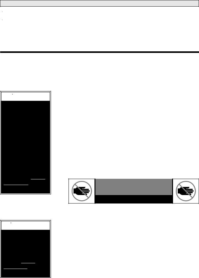
General Safety: The lift operator (attendant) and bystanders must keep clear of the area in which the lift operates and clear of all moving parts. Stand clear of doors, stepwell and platform during lift operation. The lift occupant must keep hands, arms and all other body parts within the lift occupant area and clear of moving parts.
 DANGER
KEEP CLEAR OF MOVING PARTS
81819
Become familiar with all platform features and the proper operation of the platform components before attempting lift operation. Refer to Lift Terminology on pages 2-4 for identification of and description of specific lift components if not clearly depicted in this section. Contact The Braun Corporation at 1-800-THE LIFT immediately if any of this information is not understood.
Outboard Roll Stop: The outboard roll stop is the automatic electric actuator-activated outer barrier that provides a ramp for wheelchair loading and unloading at ground level.
From ground level, the LIFT UP function switch automatically raises (rotates) the actuatoractivated roll stop to the upright (vertical) position before the
Page 7
 Loading...