


Operator's Manual
32244 Rev. B
January 2008
Operator's Manual for:
Private Use Wheelchair Lifts
DOT — Private Use Lift
“DOT — Private Use Lift” verifies that this platform lift meets only the “private use lift” requirements of FMVSS No. 403. This lift may be installed on all vehicles appropriate for the size and weight of the lift, except for buses, school buses, and multi-purpose passenger vehicles other than motor homes with a gross vehicle weight rating (GVWR) that exceeds 4,536 kg (10,000 lb).
®
"Providing Access to the World" ®
International Corporate Hdqrs: P.O. Box 310 |
Winamac, IN 46996 |
USA |
|
1-800-THE LIFT ® |
(574) 946-6153 |
FAX: (574) 946-4670 |
|
Patent #5,261,779 |
Patent #6,599,079 |
Patent #6,065,924 |
Patent #6,692,217 |
Patent #6,238,169 |
Patent #6,739,824 |
Patent #6,464,447 |
Patents Pending |
WARNING |
Operator's |
|
Oper |
||
Man ator's |
Manual |
|
ual |
||
|
||
Read manual |
|
|
before operating |
Braun |
|
lift. Failure to do |
||
so may result in |
||
serious bodily |
||
NL955 |
||
injury and/or |
||
property damage. |
||
Keep manual in |
||
lift storage pouch. |
Series |
|
|

Congratulations
We at The Braun Corporation wish to express our fullest appreciation
on your new purchase. With you in mind, our skilled craftsmen have designed and assembled the finest lift available.
This manual includes safety precautions, lift operating instructions, manual operating instructions, and instructions for maintenance and lubrication procedures.
Your lift is built for dependability, and will bring you years of pleasure and independence, as long as maintenance is performed regularly and the lift is operated by an instructed person.
Sincerely,
THE BRAUN CORPORATION
Ralph W. Braun
Chief Executive Officer
Contents
Warranty and Registration Instructions |
........... 2, 3 |
Lift Terminology |
|
Lift Terminology Illustration ........................................ |
4 |
Introduction ................................................................ |
5 |
Direction .................................................................... |
5 |
Lift Components .................................................... |
6, 7 |
Vehicle and Lift Interlocks ......................................... |
7 |
Lift Actions and Functions .......................................... |
8 |
Lift Operation Safety |
|
Safety Symbols ......................................................... |
9 |
Lift Operation Safety Precautions ...................... |
10-13 |
Operation Notes and Details |
|
Introduction .............................................................. |
14 |
General Safety .................................................. |
14, 15 |
Control Switches ................................................ |
15-17 |
Lift Features |
|
Lift-Tite™ Latches........................................ |
18, 19 |
Inboard Locator and Bridge Plate ............... |
20, 21 |
Automatic Floor Level Switching ....................... |
21 |
Outer Barrier and Side Entry ....................... |
21-23 |
Outer Barrier Latch .......................................... |
23 |
Outer Barrier and Latch Operation ................... |
24 |
Lift Passengers |
|
Passenger Orientation (Boarding Direction) |
..... 25 |
Vehicle (Floor Level) Loading and |
|
Unloading .......................................................... |
25 |
Wheelchair-Equipped Occupant Seat Belts ........... |
26 |
Operation Procedure Review ........................... |
26, 27 |
Preventive Maintenance ................................... |
27, 28 |
Lift Operating Instructions ............................. |
29-35 |
NHTSA Operations Checklist .............................. |
36 |
Manual Operating Instructions ....................... |
37-39 |
Decals and Antiskid ........................................ |
40-42 |
Maintenance and Lubrication ......................... |
43-51 |
Page 1
Warranty and Registration Instructions
Immediately upon receiving your lift, examine the unit for any damage. Notify the carrier at once with any claims.
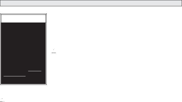
Two warranty/registration cards (shown below) are located in the lift-mounted owner’s manual storage pouch. The sales repre-
sentative must process one of the cards. The consumer must fill out the other card and mail it to The
Braun Corporation. The warranty is provided on the back cover of this manual. The warranty cards must be processed to activate the warranty.
Two Braun Serial No./Series No. Identification tags are posted on the lift. One I.D. tag (shown below) is posted on the pump side vertical arm. A second I.D. tag is located on the opposite pump
side tower. Both I.D. tags provide the product identification information appearing on the Warranty/ Registration card. Record the information in the space provided on the next page.
This information must be provided when filing a warranty claim or ordering parts.
Series No. |
Pump Code |
The Braun Corporation |
BRAUNLIFT.COMTM |
||
|
|
1-800-THE-LIFT TM |
Model No. |
Serial No. |
Cylinder Code |
|
|||||||||||
|
|
|
|
|
|
OWNER'S WARRANTY REGISTRATION |
|
|
|
|
|
|||
|
|
|
|
|
|
NL955E3143-03-00001-56-14CF |
|
|
|
|
|
|||
|
|
PURCHASED FROM |
|
|
|
|
|
|
|
|
|
|||
|
|
|
|
|
|
|
|
|
|
|
|
|
|
|
|
|
|
|
|
|
OWNER |
|
|
|
|
|
|||
|
|
|
|
|
|
|
|
|
|
DATE INSTALLED |
|
|
|
|
|
|
NAME |
|
|
|
|
|
|
|
|
|
|
Sample |
|
|
|
ADDRESS |
|
|
|
|
|
|
|
|
Sample |
|||
|
|
CITY |
|
|
|
|
|
|
|
|
|
|
||
|
|
|
|
|
|
|
|
|
|
|
Warranty/Registration |
Serial No./Series No. |
||
|
|
TELEPHONE |
|
STATE |
|
|
ZIP |
|
|
|||||
|
|
|
|
|
|
|
|
|
|
|
|
|
Card |
Identification Tag |
|
|
REGISTRATION CARDS MUST BE RETURNED TO THE BRAUN CORPORATION. |
||||||||||||
|
|
|
|
|
|
TO VALIDATE WARRANTY |
|
|
|
|
|
|||
|
|
|
|
|
|
|
|
|
|
|
|
|
|
|
DOT Private Use Lift MODEL#
NL955SE3143
Max. Lifting Capacity - 750Lbs.
SERIAL NUMBER
03-00001
PUMP CODE |
|
CYLINDER |
56 |
|
14CF |
MFG DATE
07/08/2005
 e5*72/245*95/54*0110*00
U.S. PATENT 5261779-5806632-6692217
Page 2

Warranty and Registration Instructions
Model No. |
|
|
Pump Code |
|
|||
Series No. |
|
Cylinder Code |
|
||||
Serial No. |
|
|
Date of Manufacture |
|
|||
Note: This information must be provided when filing a warranty claim or ordering parts. Keep for future use.
Page 3
|
Towers (2) |
Lift-Tite™ Latches (2) |
Lift Terminology |
|
|
|
Top Parallel Arms (2) |
||
|
Audible |
Illustration |
||
|
Main Cylinders (2) |
|||
Hand-Held |
Threshold |
|
||
|
|
|||
Warning |
Adjustable Quiet-Ride Stow Blocks (2) |
|||
Pendant |
||||
|
||||
Control |
|
|
|
|
Power |
|
|
Platform Lights |
Indicator |
|
Opposite Pump Side Vertical Arm |
|
Light |
|
||
Threshold |
|
|
|
|
Vertical Arm Covers (4) |
||
|
Warning |
||
|
|
|
|
Pump Module |
Plate |
|
Switch Arm |
|
|
|
|
Base Plate |
Inboard |
|
|
Unfold Assist Compression |
Locator |
|
|
|
Inboard |
Right |
|
Springs (2) |
|
||
|
|
|
|
Bottom Parallel Arms (2) |
|
Left |
Outboard |
|
|
||
Rotating Pivot Slide Arms (2) |
Outer Barrier |
|
|
Platform Pivot Arms (2) |
Latch |
|
Platform |
Pump Side Vertical Arm |
|
Outer Barrier Cylinder |
|
(not visible -underside of platform) |
|
Platform Side Plates (2) |
Outer Barrier |
|
|
Page 4 |
Side Entry |
|

Lift Terminology
Introduction:
Braun NL955 Millennium Series lifts comply fully with the National Highway Traffic Safety Administration (NHTSA) specifications. The Braun NL955 is consumer oriented (designed to allow operation by the wheelchair passenger). NL955 lift models provide fully automatic operation of all
lift functions as well as optional automatic door operators (if so equipped).
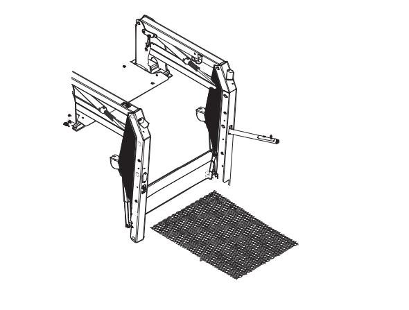
Lift models vary per platform size (lift model numbers indicate lift dimensions). A standard NL955 lift model is depicted in the Lift Terminology Illustration. Refer to
the Lift Terminology Illustration for identification of lift components.
Lift operation procedures are identical for all NL955 Series lift models. The operating instructions contained in this manual and appearing on liftposted operating instructions decals address the lift control switches and the corresponding lift functions. Instructions are provided for manual operation of the lift in event of power or equipment failure.
Terminology: Become familiar with the terminology that will be used throughout this manual.
Become familiar with the identification of lift components and their functions. Contact your lift sales representative or call The Braun Corporation at 1-800-THE LIFT® if any of this information is not fully understood.
Direction: The terms “left,” “right,” “inboard,” and “outboard” will be used throughout this manual to indicate direction (as viewed from outside the vehicle looking directly at the lift). Refer to the Lift Terminology Illustration for clarification of direction terms.
Page 5

Lift Components
Refer to the Lift Terminology Illustration on page 4.
Pump Module: The lift-mounted pump module consists of the hydraulic pump, the manual hand pump, the electronic control board and electrical components that power the lift electric/hydraulic systems. The pump module is equipped with three function-labeled control switches.
Hand-held Pendant Control:
The hand-held attendant's pendant control is connected to the pump module. The hand-held pendant is equipped with four push button switches, (UNFOLD,
Lift Terminology
FOLD, DOWN, and UP). The momentary switches activate the automatic lift functions. The lift function labels illuminate to identify the function(s).
Lift Frame: The lift frame consists of the base plate, threshold warning plate, towers, parallel arms, vertical arms, platform pivot arms and switch arm. Two main hydraulic cylinders are housed in the parallel arms. The electrical/hydraulic powered lift frame components mechanically unfold, lower, raise and fold the lift platform assembly.
Switch Arm: An additional UP/DOWN switch is provided on the switch arm.
Platform Assembly: The platform assembly consists of the steel tubing frame with grating surface upon which the wheelchair is positioned, the outer barrier, outer barrier latch, the inboard locator, side entry and the hydraulic cylinder assembly that powers the outer barrier.
Lift-Tite™ Latches: The springloaded latches prevent the platform from unfolding from the stowed position in the event of platform drift. Further details regarding Lift-Tite™ latches are provided on pages 18 and 19.
Outer Barrier: The cylinderpowered automatic outer barrier provides a ramp for wheelchair loading and unloading at ground
Page 6

level. The NL955 platform is equipped with a side entry that allows boarding and exiting in tight parking situations. The outer barrier and side entry function together in unison.
Outer Barrier Latch: The spring-loaded latch locks the outer barrier in the vertical position when the platform raises above ground level.
Inboard Locator: NL955 Series lift models are equipped with an automatic inboard locator that also serves as the bridge plate. The bridge plate bridges the gap between the lift platform and the vehicle floor. The inboard locator/bridge plate automatically rotates from the horizontal position
Lift Terminology
to the vertical position as the lift lowers and raises. Further details regarding the automatic mechanical inboard locator are provided on pages 18 and 19.
Vehicle and Lift Interlocks
Braun Corporation NL955 Series lifts comply fully with all NHTSA vehicle and lift interlock specifications. Vehicle movement is prohibited unless the lift door is closed, ensuring the lift is stowed. The lift will not function unless the vehicle is parked and secured.
The NL955 features an audible threshold warning system that will activate if the threshold area
is occupied when the platform is one inch or more below floor level.
The inboard locator and outer barrier sense weight to prohibit lift operation. The lift will not function if the inboard locator or the outer barrier are occupied. The lift platform cannot be folded (stowed) if occupied
Page 7

Lift Actions and Functions
DEPLOY (A-C)
A.UNFOLD (Out) - Platform Unfold: Unfold is the action of the platform rotating out and down from the fully-stowed (vertical) position to floor level (horizontal) position when the UNFOLD switch is pressed.
B.DOWN - Platform Lower:
Down is the action of the platform lowering from floor level position to fully-lowered (ground level) position when the DOWN switch is pressed.
C.DOWN - Outer Barrier Unfold (Deploy) - When the platform reaches the fully-low-
Lift Terminology
ered (ground) position and the DOWN switch is continued to be pressed, the outer barrier rotates downward from vertical position to ramp position.
STOW (D-F)
D.UP - Outer Barrier Fold (Raise): When the lift is fully lowered and the outer barrier is in the ramp position, pressing the UP switch first rotates the outer barrier upward from ramp position to vertical position.
E.UP - Platform Raise: Up is the action of the platform raising from ground level to floor level (fully-raised) position when the UP switch is pressed.
F. FOLD (In) - Platform Fold:
Fold is the action of the platform rotating up and in from the floor level (horizontal) position to fullystowed (vertical) position when the FOLD switch is pressed.
Stowed Position: The lift is stowed when the lift platform has been fully raised and folded fully (vertical position).
Floor Level: Floor level is the position (height) the platform assembly reaches in order for the wheelchair passenger to enter and exit the vehicle (fully raised). The platform automatically stops at floor level when unfolding from the stowed position and when raising from ground level.
Page 8
Lift Operation Safety
Safety Symbols
SAFETY FIRST! Know That ...
A |
All information contained |
B |
|
|
|
|
|
|
WARNING |
|
|||
in this manual and |
|
|
|
|||
supplements (if included), is pro- |
|
|
|
|
|
|
|
|
|
This symbol indicates |
|
||
vided for your safety. Familiarity |
|
|
|
|
||
with proper operation instructions |
|
|
|
important safety in- |
|
|
as well as proper maintenance |
|
|
|
formation regarding a |
|
|
procedures are necessary to en- |
|
|
|
potentially hazardous |
|
|
sure safe, troublefree operation. |
|
|
|
situation that could |
|
|
Safety precautions are provided |
|
|
|
result in serious |
|
|
to identify potentially hazardous |
|
|
|
bodily injury and/or |
|
|
situations and provide instruction |
|
|
|
property damage. |
|
|
on how to avoid them. |
|
|
|
|
|
|
|
|
|
|
|
||
|
|
|
|
|
||
C  CAUTION
This symbol indicates important information regarding how to avoid a hazardous situation that could result in minor personal injury or property damage.
D Note: Additional information provided to help clarify or detail a specific subject.
These symbols will appear throughout this manual as well as on the labels posted on your lift. Recognize the seriousness of this information.
Page 9

Lift Operation Safety
Lift Operation Safety Precautions
 WARNING
If the lift operating instructions, manual operating instructions and/or lift operation safety precautions are not fully understood, contact The Braun Corporation immediately. Failure to do so may result in serious bodily injury and/or
property damage.
 WARNING Read manual and supplement(s) before operating lift. Read and become familiar with all safety precautions, operation notes and details, operating instructions and manual operating instructions before operating the lift. Note: Wheelchair passengers and all transit agency personnel (drivers and wheelchair lift attendants) must read and become familiar with the contents of this manual and supplement(s) before operation.
 WARNING
 WARNING
 WARNING
Load and unload on level surface only.
Engage vehicle parking brake before operating lift.
Provide adequate clearance outside the vehicle to accommodate the lift before opening lift door(s) or operating lift.
 WARNING Inspect lift before operation. Do not operate lift if you suspect lift damage, wear or any abnormal condition.
 WARNING Keep operator and bystanders clear of area in which the lift operates.
Page 10

Lift Operation Safety

 WARNING Whenever a wheelchair passenger (or standee) is on the platform, the:
•Passenger must face outward.
•Wheelchair brakes must be locked.
•Inboard locator and outer barrier must be up (vertical).
•Outer barrier latch must be fully engaged.


 WARNING


 WARNING


 WARNING


 WARNING


 WARNING


 WARNING


 WARNING


 WARNING
Load and unload clear of vehicular traffic.
Do not overload or abuse. The load rating applies to both the raising and lowering functions - continuous lifting capacity is 750 lbs.
Discontinue lift use immediately if any lift or vehicle interlock does not operate properly.
Do not operate or board the lift if you or your lift operator are intoxicated.
Do not raise front wheelchair wheels (pull wheelie) when loading (boarding) the platform.
Open lift door(s) fully and secure before operating lift.
Position and secure (buckle, engage, fasten, etc.) the wheelchair-equipped occupant seat belt (torso restraint) before loading onto the wheelchair lift platform.
Lift attendants must ensure that lift occupants keep hands, arms and all other body parts within the lift occupant area and clear of moving parts.
Page 11
Lift Operation Safety
Lift Operation Safety Precautions
 WARNING
If the lift operating instructions, manual operating instructions and/or lift operation safety precautions are not fully understood, contact The Braun Corporation immediately. Failure to do so may result in serious bodily injury and/or
property damage.
 WARNING Platform must be positioned at floor level (bridge plate height) when loading or unloading in and out of vehicle.
 WARNING Do not use platform inboard locator or outer barrier as a barrier (brake). Stop and brake wheelchair when loading onto the platform (manually stop and brake manual wheelchairs
— stop powered wheelchairs with the wheelchair controls).
 WARNING Turn powered (electric) wheelchairs off when on lift platform.
 WARNING Press the DOWN switch until the entire platform rests on ground level (lowered fully) and the outer barrier is fully unfolded (ramp position) before loading or unloading a passenger at ground level.
 WARNING Outer barrier must be fully unfolded (ramp position) until the entire wheelchair crosses the barrier when loading or unloading at ground level.
 WARNING Accidental activation of control switch(es) may cause unintended operation(s).
Page 12

Lift Operation Safety


 WARNING Maintenance and lubrication procedures must be performed as specified in this manual by authorized (certified) service personnel.
 WARNING Replace missing, worn or illegible decals.


 WARNING Keep this operator’s manual in lift-mounted manual storage pouch when not in use.


 WARNING Never modify (alter) a Braun Corporation lift.


 WARNING Do not use accessory devices not authorized by The Braun Corporation.


 WARNING Do not remove any guards or covers.


 WARNING Keep clear of any hydraulic leak.
 WARNING Failure to follow these safety precautions may result in serious bodily injury and/or property damage.
Page 13

 WARNING
Read and become familiar with all lift operation safety precautions, operation notes and details, operating instructions and manual operating instructions prior to operating the lift.
If this information is not fully understood, contact The Braun Corporation immediately. Failure to do so may result in serious bodily injury and/or property damage.
Operation Notes and Details
NL955 Series “Private Use” lift models are designed to allow operation by the wheelchair passenger. NL955 Series lifts are typically installed in vehicles equipped with fully-automatic door operators. The NL955 provides fully automatic operation of all lift functions as well as optional automatic door operators (if so equipped).
Note: An attendant must manually open and close lift door(s) in applications where power door operator(s) are not provided.
It is the responsibility of the lift operator (attendant and/or wheelchair passenger) to properly activate all power (lift and door) functions. Read
and become familiar with all lift operation safety precautions, operation notes and details, lift operating instructions and manual operating instructions before attempting lift operating procedures.
General Safety: Before operating the lift, always engage the vehicle transmission in Park “P” and engage the vehicle parking brake. Note: Lift and vehicle interlocks prevent lift operation until the vehicle is immobilized.
Lift operators (attendants), wheelchair passengers and bystanders must keep clear of the area in which the power doors (if equipped), and the lift operates (clear of all moving parts). The lift occupant (passenger)
Page 14
Operation Notes and Details
must keep hands, arms and all |
parts. Follow all lift operation |
other body parts within the lift oc- |
and wheelchair passenger infor- |
cupant area and clear of moving |
mation detailed in this manual. |
Control Switches
Lift Power Switch
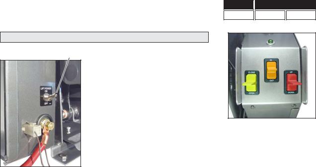
Lift Power ON/OFF Switch: This switch must be in the ON position in order to activate the lift controls. The green Power Indicator Light mounted on top of the pump module illuminates to signal power to the lift.
Lift-mounted Control Switches:
The lift-mounted control switches activate the automatic lift functions and optional door operators. The switches are function labeled. Press the switches in the direction of the function label to activate the intended lift function.
Press switches upward for these functions:
Door(s) Platform
CLOSE FOLD UP
Yellow Orange Red
Yellow |
|
Orange |
|
Red |
|
|
|
|
|
OPEN |
|
UNFOLD |
|
DOWN |
|
|
|
|
|
|
|
|
|
|
Door(s) |
|
Platform |
||
|
|
|
|
|
Press switches downward for these functions:
Page 15
 Loading...