


The Bose® Lifestyle® 25 System
Owner’s Guide
December 20, 2001
AM187718_01_V.pdf
Safety Information
Warning
To reduce the risk of fire or electric shock, do not expose this system to rain or moisture.
CAUTION |
RISK OF ELECTRICAL SHOCK |
DO NOT OPEN |
CAUTION: TO REDUCE THE RISK OF ELECTRIC SHOCK, |
DO NOT REMOVE COVER (OR BACK). |
NO USER-SERVICEABLE PARTS INSIDE. |
REFER SERVICING TO QUALIFIED PERSONNEL. |
CAUTION:
For units with a polarized power plug, to prevent electric shock, match wide blade of plug to wide slot, insert fully.
These CAUTION marks are located on the back panel and bottom of your Lifestyle® music center and the bottom panel of your Acoustimass® module:
The lightning flash with arrowhead symbol, within an equilateral triangle, is intended to alert the user to the presence of uninsulated dangerous voltage within the system enclosure that may be of sufficient magnitude to constitute a risk of electric shock.
The exclamation point within an equilateral triangle, as marked on the system, is intended to alert the user to the presence of important operating and maintenance instructions in this owner’s guide.
Class 1 laser product
CLASS 1 LASER PRODUCT
KLASSE 1 LASER PRODUKT LUOKAN 1 LASER LAITE KLASS 1 LASER APPARAT
This compact disc player is classified as a CLASS 1 LASER product. The CLASS 1 LASER PRODUCT label is located on the bottom
of the unit.
CAUTION: Use of controls or adjustments or performance of procedures other than those specified herein may result in hazardous radiation exposure. The compact disc player should not be adjusted or repaired by anyone except properly qualified service personnel.
Note: This system is not intended for use in moving vehicles.
Class B emissions limits
This digital apparatus does not exceed the Class B limits for radio noise emissions from digital apparatus set out in the Radio Interference Regulations of the Canadian Department of Communications.
Batteries
Please dispose of used batteries properly, following any local regulations. Do not incinerate.
Additional safety information
See the additional information on the Important Safety Instructions page enclosed with this owner’s guide.
Please read this owner’s guide
Please take the time to follow this owner’s guide carefully. It will help you set up and operate your system properly, and enjoy all of its advanced features. Save your owner’s guide for future reference.
2 |
December 20, 2001 |
AM187718_01_V.pdf |

Important Safety Instructions
1.Read these instructions – for all components before using this product.
2.Keep these instructions – for future reference.
3.Heed all warnings – on the product and in the owner’s guide.
4.Follow all instructions.
5.Do not use this apparatus near water or moisture – Do not use this product near a bathtub, washbowl, kitchen sink, laundry tub, in a wet basement, near a swimming pool, or anywhere else that water or moisture are present.
6.Clean only with a dry cloth – and as directed by Bose® Corporation. Unplug this product from the wall outlet before cleaning.
7.Do not block any ventilation openings. Install in accordance with the manufacturer’s instructions – To ensure reliable operation of the product and to protect it from overheating, put the product in a position and location that will not interfere with its proper ventilation. For example, do not place the product on a bed, sofa, or similar surface that may block the ventilation openings. Do not put it in a built-in system, such as a bookcase or a cabinet that may keep air from flowing through its ventilation openings.
8.Do not install near any heat sources, such as radiators, heat registers, stoves or other apparatus (including amplifiers) that produce heat.
9.Do not defeat the safety purpose of the polarized or grounding-type plug. A polarized plug has two blades with one wider than the other. A grounding-type plug has two blades and a third grounding prong. The wider blade or third prong are provided for your safety. If the provided plug does not fit in your outlet, consult an electrician for replacement of the obsolete outlet.
10.Protect the power cord from being walked on or pinched, particularly at plugs, convenience receptacles, and the point where they exit from the apparatus.
11.Only use attachments/accessories specified by the manufacturer.
12.Use only with the cart, stand, tripod,
bracket or table specified by the manufacturer or sold with the apparatus. When a cart is used, use caution when moving the cart/apparatus combination to avoid injury from tip-over.
13.Unplug this apparatus during lightning storms or when unused for long periods of time – to prevent damage to this product.
14.Refer all servicing to qualified service personnel. Servicing is required when the apparatus has been damaged in any way: such as powersupply cord or plug is damaged; liquid has been spilled or objects have fallen into the apparatus; the apparatus has been exposed to rain or moisture, does not operate normally, or has been dropped – Do not attempt to service this product yourself. Opening or removing covers may expose you to dangerous voltages or other hazards. Please call Bose to be referred to an authorized service center near you.
15.To prevent risk of fire or electric shock, avoid overloading wall outlets, extension cords, or integral convenience receptacles.
16.Do not let objects or liquids enter the product – as they may touch dangerous voltage points or short-out parts that could result in a fire or electric shock.
17.See product enclosure for safety related markings.
Information about products that generate electrical noise
If applicable, this equipment has been tested and found to comply with the limits for a Class B digital device, pursuant to Part 15 of the FCC rules. These limits are designed to provide reasonable protection against harmful interference in a residential installation. This equipment generates, uses, and can radiate radio frequency energy and, if not installed and used in accordance with the instructions, may cause harmful interference to radio communications. However, this is no guarantee that interference will not occur in a particular installation. If this equipment does cause harmful interference to radio or television reception, which can be determined by turning the equipment off and on, you are encouraged to try to correct the interference by one or more of the following measures:
•Reorient or relocate the receiving antenna.
•Increase the separation between the equipment and receiver.
•Connect the equipment to an outlet on a different circuit than the one to which the receiver is connected.
•Consult the dealer or an experienced radio/TV technician for help.
Note: Unauthorized modification of the receiver or radio remote control could void the user’s authority to operate this equipment.
This product complies with the Canadian ICES-003 Class B specifications.
AM187718_01_V.pdf |
December 20, 2001 |
a |
Important Safety Instructions
18.Use proper power sources – Plug the product into a proper power source, as described in the operating instructions or as marked on the product.
19.Avoid power lines – Use extreme care when installing an outside antenna system to keep from touching power lines or circuits, as contact with them may be fatal. Do not install external antennas near overhead power lines or other electric light or power circuits, nor where an antenna can fall into such circuits or power lines.
20.Ground all outdoor antennas – If an external antenna or cable system is connected to this product, be sure the antenna or cable system is grounded. This will provide some protection against voltage surges and built-up static charges.
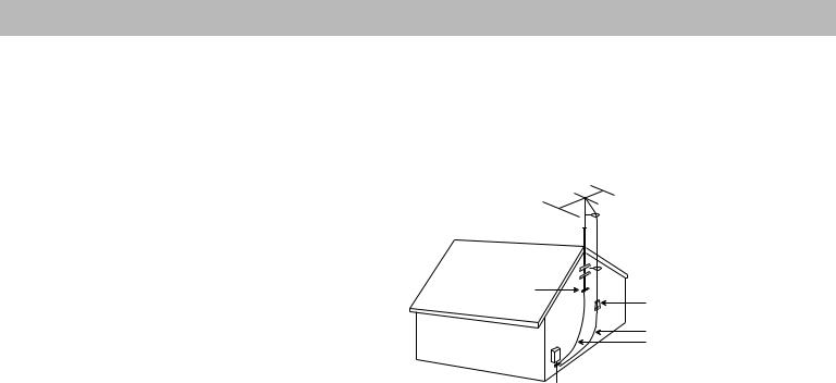
Section 810 of the National Electrical Code ANSI/ NFPA No. 70 provides information with respect to proper grounding of the mast and supporting structure, grounding of the lead-in wire to an antenna discharge unit, size of grounding conductors, location of antenna-discharge unit, connection to grounding electrodes, and requirements for the ground electrode. Refer to the antenna grounding illustration on this page.
Antenna grounding
Example of antenna grounding as per National Electrical Code, ANSI/NFPA 70.
 Antenna lead in wire
Ground clamp |
Antenna discharge unit |
|
|
|
(NEC Section 810-20) |
Electric service |
Grounding conductors |
(NEC Section 810-21) |
equipment


 Ground clamps

 Power service grounding electrode system
(NEC ART 250, Part H)
Note to CATV system installer
This reminder is provided to call the CATV system installer’s attention to Article 820-40 of the NEC (of USA) that provides guidelines for proper grounding. In particular, it specifies that the cable ground shall be connected to the grounding system of the building, as close to the point of cable entry as is practical.
b |
December 20, 2001 |
AM187718_01_V.pdf |

Contents
Where to find… |
|
|
Setting Up |
|
|
Before you begin ........................................................................................................ |
|
4 |
Unpack the carton ...................................................................................................... |
|
5 |
Select the locations for your Lifestyle® 25 system ...................................................... |
|
6 |
Connect the speakers and music center .................................................................... |
|
8 |
Connecting your home theater components to the Lifestyle® system ..................... |
10 |
|
Other connections .................................................................................................... |
|
12 |
Connect the antennas .............................................................................................. |
|
13 |
Set up the remote control ......................................................................................... |
|
14 |
Set radio channel spacing on dual voltage systems ................................................ |
|
14 |
Operating Your Lifestyle® 25 System |
|
|
Turn on your Lifestyle® 25 system ............................................................................ |
|
15 |
The music center display .......................................................................................... |
|
15 |
The system controls ................................................................................................. |
|
16 |
Other music center controls ..................................................................................... |
|
17 |
The Lifestyle® 25 remote control ............................................................................... |
|
17 |
Listening to compact discs ...................................................................................... |
|
18 |
Listening to the radio ................................................................................................ |
|
20 |
Using the system with external components ........................................................... |
|
21 |
Fine-tuning your system ........................................................................................... |
|
22 |
Using two listening zones ......................................................................................... |
|
23 |
Maintaining Your Lifestyle® 25 System |
|
|
Changing the house code settings ........................................................................... |
|
25 |
Troubleshooting ........................................................................................................ |
|
26 |
Warranty period ........................................................................................................ |
|
27 |
Customer service ..................................................................................................... |
|
27 |
Taking care of your Lifestyle® 25 system .................................................................. |
|
28 |
Product Information |
|
|
Technical information ............................................................................................... |
|
29 |
Accessories .............................................................................................................. |
|
29 |
Index ............................................................................................................................... |
|
30 |
Bose® Corporation ................................................................................. |
inside back cover |
|
For your records
Serial numbers are located on the bottom of the music center and the bottom panel of the Acoustimass® module.
Lifestyle® music center serial number: _____________________________________________
Acoustimass module serial number: ______________________________________________
Dealer name: __________________________________________________________________
Dealer phone: _______________________ Purchase date: ___________________________
We suggest you keep your sales receipt and warranty card together with this owner’s guide.
AM187718_01_V.pdf |
December 20, 2001 |
3 |

Setting Up
Before you begin
Thank you for purchasing the Bose® Lifestyle® 25 system. This complete audio home entertainment system offers superb sound, elegance, technology, and simplicity for music and home theater. Please take the time to follow this owner’s guide carefully. It will help you set up and operate your Lifestyle® system and enjoy all of its advanced features. Save your owner’s guide for future reference.
Your system includes:
•A Lifestyle® music center with built-in AM/FM radio and six-disc CD changer
•Powered Acoustimass® speakers with a hide-away Acoustimass module
•An easy-to-use remote control
•Inputs for two video sound sources, an auxiliary source, and a tape deck
•Capability for operating two listening zones
Bose VideoStageTM decoder technology enables the Lifestyle® 25 system to reproduce the realism of movie sound especially for a home environment. When a movie soundtrack or CD is produced in a surround sound format, specially encoded sound is sent to any or all of the available speakers. Dialogue is usually sent to the front speakers. Sounds from the left or right side of the picture are sent to left or right front speakers. Ambient sounds or special effects may be sent to the surround (rear) speakers. Bose VideoStage circuitry automatically directs the sound to the correct speakers.
To select surround-encoded material, look for any of the terms Surround, Dolby Surround, and the double-D symbol 
 * on tapes and discs, or the word “surround” preceding a TV broadcast.
When sound is recorded in stereo, but not surround-encoded, VideoStage decoder technology directs it to the most appropriate speakers based on the signals received. When viewing older movies or listening to other monaural programs on your Lifestyle® 25 system, VideoStage directs sound so it appears to come from the center of the TV screen.
You can listen to any program material in SURROUND (5-speaker) mode, whether the program is surround-encoded, stereo, or monaural. You will not hear sound from all five speakers all of the time. Even with surround-encoded material there are times when no sounds are directed to the surround speakers. You can select the speaker mode that sounds best to you for each particular program.
* Dolby and the double-D symbol are trademarks of Dolby Laboratories Licensing Corporation.
4 |
December 20, 2001 |
AM187718_01_V.pdf |

Setting Up
CAUTION:
Remove and dispose of the three red manufacturer’s shipping screws from the bottom of the Lifestyle® music center before setting up your system.
The shipping screws are for use by the manufacturer only. They are not re-installable.
Unpack the carton
Carefully unpack your system. Save all packing materials for possible future use. The original packing materials provide the safest way to transport your Lifestyle® system. If any part of the product appears damaged, do not attempt to use the system. Notify Bose® customer service or your authorized Bose dealer immediately.
Use care when you remove the protective plastic film from the music center to avoid scratching the finish.
Check to be sure your Lifestyle® 25 system contains the parts identified in Figure 1.
Note: Find the serial numbers on the bottom panel of the Acoustimass® module and the bottom of the music center. Write them on your warranty card and in the spaces provided on page 3.
Figure 1
What comes with your
Lifestyle® 25 system:
•Lifestyle® music center
•Music center power pack*
•5 cube speaker arrays
•5 speaker cables
(2 surround and 3 front)
•Acoustimass module
•4 self-adhesive rubber feet (for the Acoustimass module)
•AC power (mains) cord*
•Audio input cable
•Stereo cable
•Remote control
•3 AA batteries
•FM antenna
•AM antenna
•CD magazine
•Lifestyle® CD and Test CD
* Power cord and pack shown in Figure 1 are USA/Canada/Japan versions.
Dual voltage systems include 1 power cord, 1 adapter 
 , and 2 power packs.
The power cords and packs for Europe, UK/Singapore, and Australia are shown below.
Europe
UK/Singapore
|
Treble |
|
|
|
|
|
|
Bass |
|
|
|
|
|
|
Acoustimass module |
|
|
Lifestyle® music center |
||
|
|
|
|
Audio input cable |
|
|
Cube speaker |
|
|
|
|
|
|
|
arrays |
|
|
|
|
|
|
|
|
Music center power pack |
|
||
|
Surround speaker cables |
AA |
|
|
CD magazine |
|
AC power cord |
batteries |
|
|
|||
(orange connectors) |
|
|
|
|
||
|
|
|
Remote |
|
||
|
|
|
|
|
|
|
|
|
|
|
|
control |
|
Front speaker cables |
|
|
|
AM antenna |
||
(blue connectors) |
FM antenna |
|
|
|
||
|
|
|
|
|
THE BOSE |
|
|
|
|
|
|
S |
|
|
|
|
|
|
PECIAL EDITION |
LIFESTYLE |
|
|
|
|
|
|
M |
|
|
|
|
|
|
USIC SYSTEM CD |
Rubber feet |
Stereo cable |
|
|
|
|
|
|
|
|
Test CD |
Lifestyle® CD |
||
|
|
|
|
|
||
Australia
AM187718_01_V.pdf |
December 20, 2001 |
5 |
Setting Up
Select the locations for your Lifestyle® 25 system
When you place your speakers according to the guidelines below, a combination of reflected and direct sound provides the audio atmosphere of a home theater. You may experiment with the placement and orientation of the cubes to produce the sound most pleasing to you. For the best surround effect, adjust the speakers so you cannot identify the exact sound source. It is preferable not to aim the cubes directly at the listener. For more discussion of speaker placement and room acoustics, see “Fine-tuning your system” on page 22.
CAUTION:
Choose a stable and level surface for your speakers. Vibration can cause the speakers to move, particularly on smooth surfaces like marble, glass, or highly polished wood. For additional stability, you can add rubber feet to your speakers. You may obtain rubber feet (part no. 178321), free of charge, from Bose®. Contact Bose Customer Service (see listings on the inside back cover).
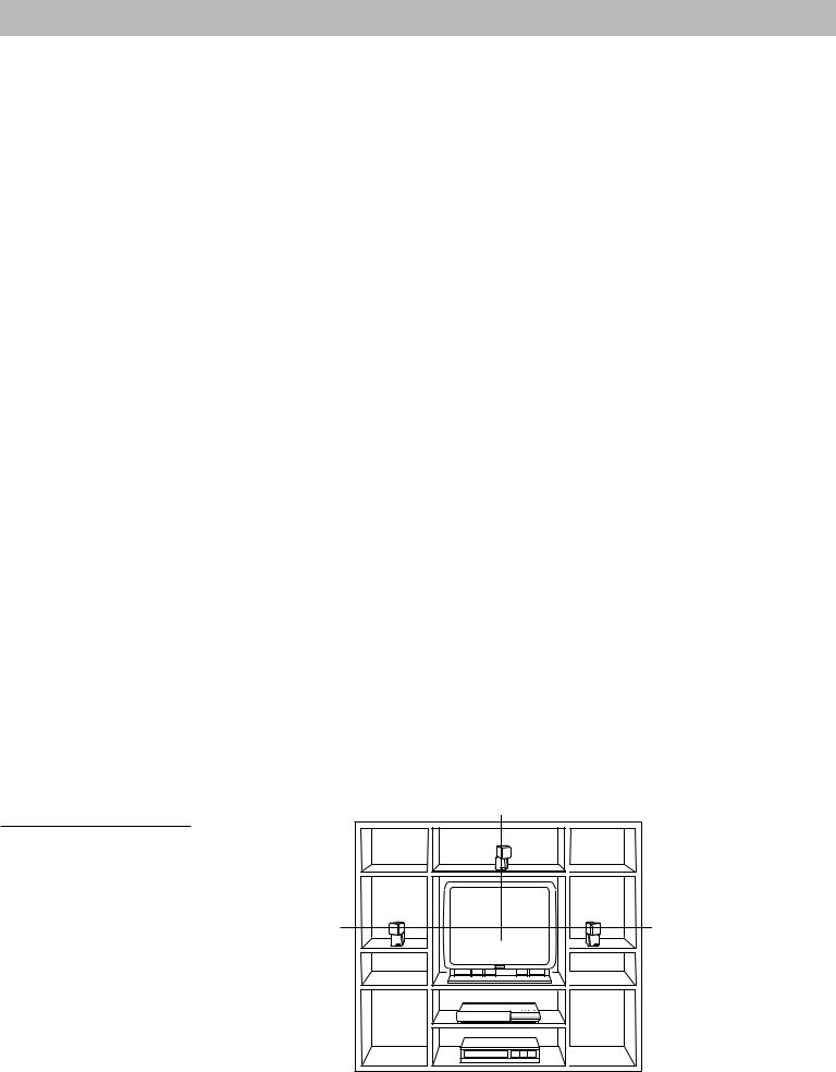
Figure 2
Recommended front speaker locations
6
Speaker locations
Follow these guidelines to select locations that provide the maximum home theater effect from your Lifestyle® 25 system (Figures 2 and 3).
Left and right front speakers
The sound from the left and right front speakers should seem to appear at the edge of the picture, so that the acoustic image is close to the size of the visual image (Figure 2).
1.Place them on line with the horizontal center of the TV screen.
2.Place each speaker up to 3 feet (1 m) from the edge of the TV screen.
We recommend a maximum distance of 3 feet (1 m) so that the sound does not become too separated from the picture. You may wish to vary this distance based on room conditions and personal preference. The front cables allow the cube speakers to be placed up to 20 feet (6.1 m) from the Acoustimass® module.
3.Direct one cube of each array forward. Direct the other cube toward the wall or in a different direction to create reflected sound. (See the illustration of reflected sound patterns in Figure 3.)
Note: The cube speakers are magnetically shielded so you can place them close to the TV without affecting picture quality.
Center speaker
The sound from the center speaker should appear to come directly from the center of the picture (Figure 2). The center cable allows the center speaker to be placed up to 20 feet (6.1 m) from the Acoustimass module.
1.Place the speaker on line with the vertical center of the screen, above or below (whichever is closer to the screen), or the closest convenient location.
2.Place the speaker in line with the front of the screen (not pushed to the back of the TV).
3.Direct each of the cubes slightly away from center, to create a wider area of direct sound (Figure 3).
Note: If you put the speakers in a bookcase unit, be sure to place each one at the front edge of the shelf. Placing speakers in an enclosed space can change the tonal quality of the sound. This effect is minimized if the shelves are filled with books.
|
Center |
Left front |
Right front |
December 20, 2001 |
AM187718_01_V.pdf |
Setting Up
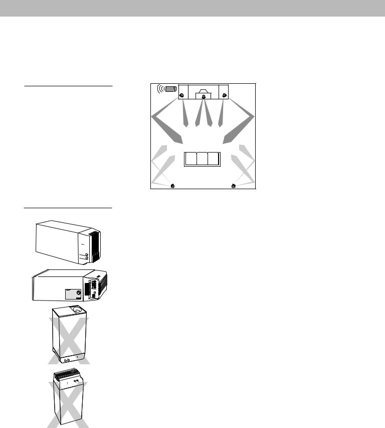
Figure 3
Speaker placement
Figure 4
Acoustimass module positions
Preferred
position
Alternate position
CAUTION:
Do not cover the ventilation openings of the Acoustimass module. The slots on the end provide ventilation for the built-in electronic circuitry.
Surround speakers
The surround (rear) speakers create an area of sound around the listener. Place them in the back half of your room. Direct the cubes so that you do not pinpoint the exact location of the sound source (Figure 3). The surround cables allow the speakers to be placed up to 50 feet (15.2 m) from the Acoustimass® module.
Acoustimass module |
Center |
|
|
|
|
1. |
Place the speakers at ear |
|
|
|
height or higher, if possible. |
Left |
Right |
2. |
Direct the cubes to reflect |
front |
front |
|
sound off one or more walls |
|
|
|
|
|
|
|
or vertical surfaces. The |
|
|
|
longer the path from the |
|
|
|
speaker to your ear, the |
|
|
|
better. |
|
|
3. |
Do not direct the sound |
Left |
Right |
|
straight at the listener. |
|
|
||
surround |
surround |
|
|
Acoustimass module
Follow these guidelines to select a location for the Acoustimass module.
CAUTION: To avoid interference with the TV picture, place the module at least 18 inches (45 cm) from the TV.
1.Place the module along the same wall as the TV, or close to the same end of the room as the front speakers (see the example along the front wall in Figure 3).
2.Select a position for the module (Figure 4). For proper ventilation, place it on the long edge, with the connectors facing the floor. An alternate position is on its largest side, with the bass and treble controls facing up. Do not place the module on either end, as shown by the last two views in Figure 4.
Note: Once you have selected a position for the module, place the four self-adhesive rubber feet near the corners of the bottom surface. The rubber feet provide increased stability and protection from scratches.
3.Select a convenient location – under a table, behind a sofa. Do not allow furniture or drapes to block the ventilation openings of the module.
4.Place it within reach of the audio input cable, speaker cables, and an electric outlet.
5.Aim the port (the round opening) into the room or along the wall to avoid blocking the port or creating too much bass.
6.For best bass performance, do not place the module so that the port is at equal distances from any two walls or from a wall and the ceiling.
Music center
Select a location for the music center.
CAUTION: Be sure the three shipping screws on the bottom of the music center have been removed before proceeding.
1.Place the music center on a level surface. Allow enough room to lift the door and to access the headphone jack on the right side panel.
2.Place the music center close enough to the sound sources (TV, VCR, etc.) to allow for cable length. If you need additional audio and/or video cables to connect all of your components, see your dealer or call Bose® customer service.
3.Place the music center within 30 feet (9.1 m) of the Acoustimass module (the length of the audio input cable).
AM187718_01_V.pdf |
December 20, 2001 |
7 |
Setting Up
CAUTION:
Make sure all components are unplugged from the power outlet before you begin connecting the system.
Figure 5
Speaker cable connections to the cube speaker array
CAUTION:
Make sure no strands of wire from any terminal touch any other terminal. Bridged wires create short circuits that affect proper operation of your system.
Connect the speakers and music center
Once you have selected locations for your speakers and music center, connect the system.
Connecting the cube speaker arrays to the Acoustimass® module
Each speaker cable contains two wires. The wire marked with a red collar is positive (+) and the plain one is negative (–). These wires match the positive (red) and negative (black) terminals on the back of each speaker.
To lengthen the cable, use RCA extension cables or splice in 18-gauge or thicker cord (connecting + to + and – to –). To purchase cables, see your dealer, electronics store, or call Bose® customer service.
Note: The surround cables are joined together for your convenience, providing an easy-to- use cable for connecting the surround speakers. To run the cables in different directions from the Acoustimass module, simply pull apart the cables as needed.
1.Match the correct cable to the corresponding speaker location.
•Front speaker cables have blue connectors at one end, with L, R, and C molded into the connectors. The red collars on the + wire are labeled LEFT, RIGHT, and CENTER.
•Surround speaker cables have orange connectors at one end, with L and R molded into the connectors. The red collars on the + wire are labeled LEFT and RIGHT.
2.Connect the wire end of one speaker cable to the terminals on the rear of the matching cube speaker array.
a. Push each of the two terminal tabs in, then insert the end of the appropriate wire into the exposed hole. Release the tab to secure the wire. Connect each wire to its corresponding terminal red to red (+ to +) and black to black (– to –).
b. Repeat this step for each of the five cube speaker arrays. (Figure 5.)
3.Connect each cable to the corresponding jack on the Acoustimass module.
a. Plug the blue connectors into the matching left front, center, and right front jacks.
b. Plug the orange connectors into the matching left surround and right surround jacks.
Connecting the Acoustimass module to the music center
Connect the module to the music center with the audio input cable (Figure 6).
1.Plug the small black multi-pin connector (flat side facing up) into the jack marked SPEAKER ZONE 1 on the back of the music center.
2.Insert the right-angle multi-pin connector on the other end of the audio input cable into the AUDIO INPUT jack on the module. Align the connector at the angle shown in Figure 6.
Note: Be sure that each connector is inserted completely into each jack.
3.Extend the audio input cable as much as possible, since it includes an antenna for the remote control.
For information on connecting zone 2, see “Using two listening zones” on pages 23-24.
8 |
December 20, 2001 |
AM187718_01_V.pdf |
Setting Up
Figure 6
Connecting the speakers and the music center
 Right front speaker
Right surround speaker
Multi-pin connector into
SPEAKER ZONE 1
Center |
|
Left front |
speaker |
|
speaker |
Right-angle connector |
Left |
|
into AUDIO INPUT |
||
|
|
surround |
|
|
speaker |
AUDIO |
|
|
INPUT |
|
|
SURROUND |
FRONT |
|
RIGHT |
RIGHT |
|
LEFT |
CENTER |
|
|
LEFT |
|
OUTPUTS TO |
|
|
CUBE SPEAKERS |
|
|
Audio
Power jack
input cable
L |
R L |
R |
TAPE IN |
|
TAPE OUT |
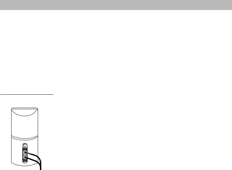
Figure 7
Dual voltage Acoustimass module: voltage selector switch settings
230 V
115 V
CAUTION:
Make sure the voltage selector switch is set correctly.
Figure 8
The AC power pack (model PS71 shown)
CAUTION:
Be sure to use the correct power pack for your area. Using the wrong one may damage your music center.
AC power pack
Connecting the Acoustimass® module power cord
1.On a dual voltage Acoustimass module, the voltage selector switch is preset at the factory. If it is not set for the proper voltage, slide it to the correct setting (Figure 7). Use 115V for North America, and 230V for Europe and Australia. In Europe, use the adapter plug provided. If you are in doubt, contact your local electric utility for the appropriate voltage setting.
2.Plug the small end of the AC power (mains) cord into the module power jack.
Note: Do not plug the power cord into a power outlet until you complete all connections.
Connecting the music center power pack
The Lifestyle® music center comes with either a 100V, 120V, 230V, or 240V power pack. See Figures 1 and 8. Dual voltage models include both the PS71 and PS72 power packs.
Use only the Bose® power pack model specified for your area:
• |
Model PS71, |
120V in North America |
• Model PS72, |
230V in Europe |
• |
Model PS73, |
100V in Japan |
• Model PS74, |
230V in UK or Singapore |
• Model PS77, 240V in Australia
1.Firmly insert the small connector on the end of the power pack cable into the AC power jack on the back of the Lifestyle® music center.
2.Make sure that the power pack reaches an AC power (mains) outlet.
Note: Do not plug the power pack into a power outlet until you complete all connections.
AM187718_01_V.pdf |
December 20, 2001 |
9 |
 Loading...