


The Bose® Lifestyle® 20 Music System
Owner’s Guide
October 29, 2001
AM178934_09_V.pdf
Safety Information
Warning
To reduce the risk of fire or electric shock, do not expose this system to rain or moisture.
CAUTION |
RISK OF ELECTRICAL SHOCK |
DO NOT OPEN |
CAUTION: TO REDUCE THE RISK OF ELECTRIC SHOCK, |
DO NOT REMOVE COVER (OR BACK). |
NO USER-SERVICEABLE PARTS INSIDE. |
REFER SERVICING TO QUALIFIED PERSONNEL. |
CAUTION:
For units with a polarized power plug, to prevent electric shock, match wide blade of plug to wide slot, insert fully.
These CAUTION marks may be located on the back panel and bottom of your Lifestyle® music center and the bottom panel of your Acoustimass® module:
The lightning flash with arrowhead symbol, within an equilateral triangle, is intended to alert the user to the presence of uninsulated dangerous voltage within the system enclosure that may be of sufficient magnitude to constitute a risk of electric shock.
The exclamation point within an equilateral triangle, as marked on the system, is intended to alert the user to the presence of important operating and maintenance instructions in this owner’s guide.
Class 1 laser product
CLASS 1 LASER PRODUCT
KLASSE 1 LASER PRODUKT LUOKAN 1 LASER LAITE KLASS 1 LASER APPARAT
This compact disc player is classified as a CLASS 1 LASER product. The CLASS 1 LASER PRODUCT label is located on the bottom
of the unit.
CAUTION: Use of controls or adjustments or performance of procedures other than those specified herein may result in hazardous radiation exposure. The compact disc player should not be adjusted or repaired by anyone except properly qualified service personnel.
Note: This music system is not intended for use in moving vehicles.
Class B emissions limits
This digital apparatus does not exceed the Class B limits for radio noise emissions from digital apparatus set out in the Radio Interference Regulations of the Canadian Department of Communications.
Batteries
Please dispose of used batteries properly, following any local regulations. Do not incinerate.
Additional safety information
See the additional information on the Important Safety Instructions page enclosed with this owner’s guide.
Please read this owner’s guide
Please take the time to follow this owner’s guide carefully. It will help you set up and operate your system properly, and enjoy all of its advanced features. Save your owner’s guide for future reference.
2 |
October 29, 2001 |
AM178934_09_V.pdf |

Important Safety Instructions
1.Read these instructions – for all components before using this product.
2.Keep these instructions – for future reference.
3.Heed all warnings – on the product and in the owner’s guide.
4.Follow all instructions.
5.Do not use this apparatus near water or moisture – Do not use this product near a bathtub, washbowl, kitchen sink, laundry tub, in a wet basement, near a swimming pool, or anywhere else that water or moisture are present.
6.Clean only with a dry cloth – and as directed by Bose® Corporation. Unplug this product from the wall outlet before cleaning.
7.Do not block any ventilation openings. Install in accordance with the manufacturer’s instructions – To ensure reliable operation of the product and to protect it from overheating, put the product in a position and location that will not interfere with its proper ventilation. For example, do not place the product on a bed, sofa, or similar surface that may block the ventilation openings. Do not put it in a built-in system, such as a bookcase or a cabinet that may keep air from flowing through its ventilation openings.
8.Do not install near any heat sources, such as radiators, heat registers, stoves or other apparatus (including amplifiers) that produce heat.
9.Do not defeat the safety purpose of the polarized or grounding-type plug. A polarized plug has two blades with one wider than the other. A grounding-type plug has two blades and a third grounding prong. The wider blade or third prong are provided for your safety. If the provided plug does not fit in your outlet, consult an electrician for replacement of the obsolete outlet.
10.Protect the power cord from being walked on or pinched, particularly at plugs, convenience receptacles, and the point where they exit from the apparatus.
11.Only use attachments/accessories specified by the manufacturer.
12.Use only with the cart, stand, tripod,
bracket or table specified by the manufacturer or sold with the apparatus. When a cart is used, use caution when moving the cart/apparatus combination to avoid injury from tip-over.
13.Unplug this apparatus during lightning storms or when unused for long periods of time – to prevent damage to this product.
14.Refer all servicing to qualified service personnel. Servicing is required when the apparatus has been damaged in any way: such as powersupply cord or plug is damaged; liquid has been spilled or objects have fallen into the apparatus; the apparatus has been exposed to rain or moisture, does not operate normally, or has been dropped – Do not attempt to service this product yourself. Opening or removing covers may expose you to dangerous voltages or other hazards. Please call Bose to be referred to an authorized service center near you.
15.To prevent risk of fire or electric shock, avoid overloading wall outlets, extension cords, or integral convenience receptacles.
16.Do not let objects or liquids enter the product – as they may touch dangerous voltage points or short-out parts that could result in a fire or electric shock.
17.See product enclosure for safety related markings.
Information about products that generate electrical noise
If applicable, this equipment has been tested and found to comply with the limits for a Class B digital device, pursuant to Part 15 of the FCC rules. These limits are designed to provide reasonable protection against harmful interference in a residential installation. This equipment generates, uses, and can radiate radio frequency energy and, if not installed and used in accordance with the instructions, may cause harmful interference to radio communications. However, this is no guarantee that interference will not occur in a particular installation. If this equipment does cause harmful interference to radio or television reception, which can be determined by turning the equipment off and on, you are encouraged to try to correct the interference by one or more of the following measures:
•Reorient or relocate the receiving antenna.
•Increase the separation between the equipment and receiver.
•Connect the equipment to an outlet on a different circuit than the one to which the receiver is connected.
•Consult the dealer or an experienced radio/TV technician for help.
Note: Unauthorized modification of the receiver or radio remote control could void the user’s authority to operate this equipment.
This product complies with the Canadian ICES-003 Class B specifications.
AM178934_09_V.pdf |
October 29, 2001 |
2a |
Important Safety Instructions
18.Use proper power sources – Plug the product into a proper power source, as described in the operating instructions or as marked on the product.
19.Avoid power lines – Use extreme care when installing an outside antenna system to keep from touching power lines or circuits, as contact with them may be fatal. Do not install external antennas near overhead power lines or other electric light or power circuits, nor where an antenna can fall into such circuits or power lines.
20.Ground all outdoor antennas – If an external antenna or cable system is connected to this product, be sure the antenna or cable system is grounded. This will provide some protection against voltage surges and built-up static charges.
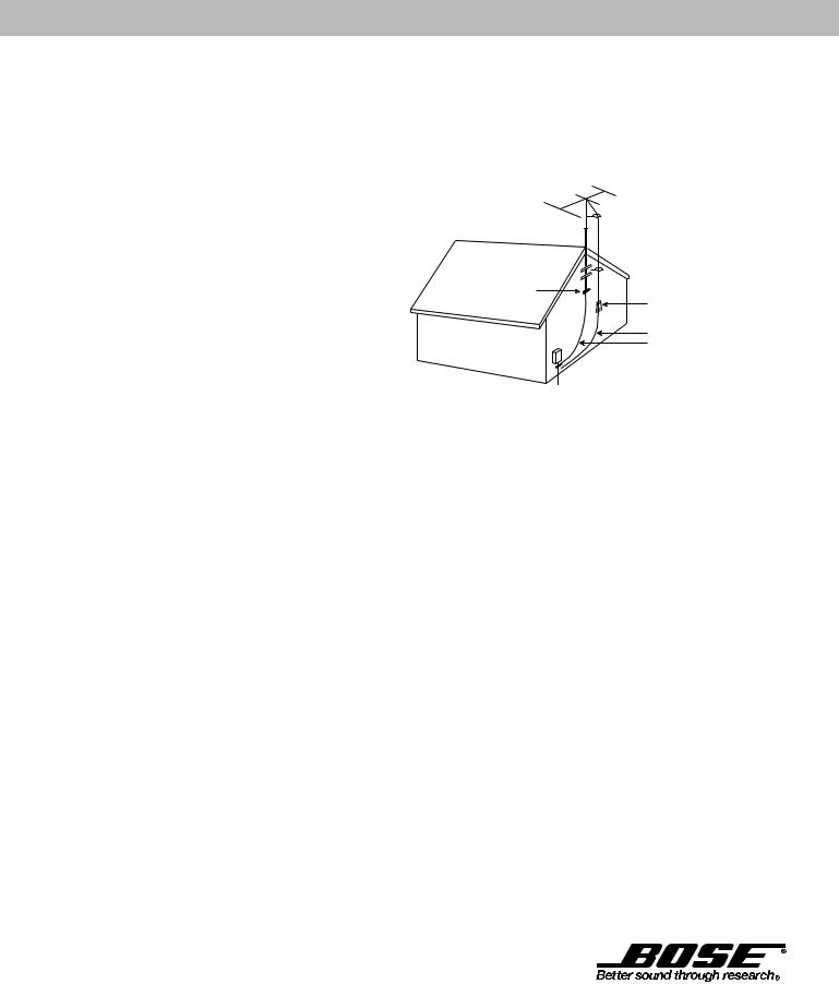
Section 810 of the National Electrical Code ANSI/ NFPA No. 70 provides information with respect to proper grounding of the mast and supporting structure, grounding of the lead-in wire to an antenna discharge unit, size of grounding conductors, location of antenna-discharge unit, connection to grounding electrodes, and requirements for the ground electrode. Refer to the antenna grounding illustration on this page.
Antenna grounding
Example of antenna grounding as per National Electrical Code, ANSI/NFPA 70.
 Antenna lead in wire
Ground clamp |
Antenna discharge unit |
|
|
|
(NEC Section 810-20) |
Electric service |
Grounding conductors |
(NEC Section 810-21) |
equipment


 Ground clamps

 Power service grounding electrode system
(NEC ART 250, Part H)
Note to CATV system installer
This reminder is provided to call the CATV system installer’s attention to Article 820-40 of the NEC (of USA) that provides guidelines for proper grounding. In particular, it specifies that the cable ground shall be connected to the grounding system of the building, as close to the point of cable entry as is practical.
©2001 Bose Corporation,
The Mountain, Framingham, MA
01701-9168 USA
255805 AM Rev.00 JN10494
2b |
October 29, 2001 |
AM178934_09_V.pdf |

Contents
Where to find… |
|
Setting Up |
|
Before you begin ........................................................................................................ |
4 |
Unpack the carton ...................................................................................................... |
5 |
Select the locations for your Lifestyle® 20 music system ........................................... |
6 |
Connect the speakers and Lifestyle® music center .................................................... |
7 |
Other connections ...................................................................................................... |
8 |
Connect the antennas ................................................................................................ |
9 |
Set up the remote control ......................................................................................... |
10 |
Set radio channel spacing on dual voltage systems ................................................ |
10 |
Operating Your Lifestyle® 20 Music System |
|
Listening to your Lifestyle® 20 music system ........................................................... |
11 |
The music center display .......................................................................................... |
11 |
The system controls ................................................................................................. |
12 |
Other music center controls ..................................................................................... |
13 |
The Lifestyle® 20 remote control ............................................................................... |
13 |
Listening to compact discs ...................................................................................... |
14 |
Listening to the radio ................................................................................................ |
16 |
Using the system with external components ........................................................... |
17 |
Fine-tuning your system ........................................................................................... |
18 |
Using two listening zones ......................................................................................... |
19 |
Maintaining Your Lifestyle® 20 Music System |
|
Changing the house code settings ........................................................................... |
21 |
Troubleshooting ........................................................................................................ |
22 |
Transporting your music center ............................................................................... |
23 |
Warranty period ........................................................................................................ |
23 |
Customer service ..................................................................................................... |
23 |
Taking care of your Lifestyle® 20 music system ....................................................... |
24 |
Product Information |
|
Technical information ............................................................................................... |
25 |
Accessories .............................................................................................................. |
25 |
Index ............................................................................................................................... |
26 |
Bose® Corporation ................................................................................. |
inside back cover |
For your records
Serial numbers are located on the bottom of the music center and the bottom panel of the Acoustimass® module.
Lifestyle® music center serial number: _____________________________________________
Acoustimass module serial number: ______________________________________________
Dealer name: __________________________________________________________________
Dealer phone: _______________________ Purchase date: ___________________________
We suggest you keep your sales slip and warranty card together with this owner’s guide.
AM178934_09_V.pdf |
October 29, 2001 |
3 |

Setting Up
Before you begin
Thank you for purchasing the Bose® Lifestyle® 20 music system. This remarkably compact system is a result of advanced technology developed by years of research. Technological innovations that make the Lifestyle® 20 music system possible include the smallest CD changer now available for home use and Jewel CubeTM speakers one-half the size of the previous Acoustimass® cube speakers.
To create speakers this small, the magnet inside is formed using the rare earth element neodymium and has ten times more energy (per unit volume) than conventional magnets. For high performance from such a small package, a port 3.8 inches (9.7 cm) long was designed in the shape of a nautilus shell and enclosed inside the tiny cube.
These, and numerous other innovations, bring you the Lifestyle® 20 music system, offering superb sound, elegance, technology, and simplicity for music and home entertainment.
Your system includes:
•A Lifestyle® music center with built-in AM/FM radio and six-disc CD changer
•Powered Acoustimass speakers consisting of two Jewel Cube speakers and a hide-away Acoustimass module
•An easy-to-use remote control
•Inputs for two video sound sources, an auxiliary source, and a tape deck
•Capability for operating two listening zones
Your Lifestyle® music system offers several ways to listen to superbly reproduced sound. You can use its built-in sound sources, connect additional equipment such as a tape deck, laserdisc player, VCR, or TV, and use two listening zones.
Please take the time to follow this owner’s guide carefully. It will help you set up and operate your Lifestyle® music system, and enjoy all of its advanced features. Save your owner’s guide for future reference.
CAUTION:
Remove and dispose of the three manufacturer’s shipping screws from the bottom of the Lifestyle® music center before setting up your system.
The shipping screws are for use by the manufacturer only. They are not re-installable.
4 |
October 29, 2001 |
AM178934_09_V.pdf |

Unpack the carton
Carefully unpack your system. Save all packing materials for possible future use. The original packing materials provide the safest way to transport your Lifestyle® system. If any part of the product appears damaged, do not attempt to use the system. Notify Bose® or your authorized Bose dealer immediately.
Check to be sure your Lifestyle® 20 music system contains the parts identified in Figure 1.
Note:Find the serial numbers on the bottom panel of the Acoustimass® module and the bottom of the music center. Write them on your warranty card and in the spaces provided on page 3.
|
Rubber feet (4) |
|
Rubber feet (4) |
Jewel CubeTM speakers |
|
Acoustimass® module |
||
|
AC power cord |
|
|
Music center power pack |
|
® |
|
Lifestyle music center |
|
Audio input cable |
|
|
AA batteries |
|
Remote |
|
control |
|
|
|
|
|
THE BOSE |
|
|
SPECIAL EDITION |
LIFESTYLE |
|
|
MUSIC SYSTEM CD |
FM antenna |
Speaker cords |
|
CD magazine |
||
|
||
|
CD |
|
|
AM antenna |
Setting Up
Figure 1
What comes with your
Lifestyle® 20 system:
•Lifestyle® music center
•Music center power pack*
•2 Jewel Cube speakers
•2 speaker cords (20')
•Acoustimass module
•8 self-adhesive rubber feet (4 for the module and
4 for the Jewel Cube speakers)
•AC power (mains) cord*
•Audio input cable (30')
•Remote control
•3 AA batteries
•FM antenna
•AM antenna
•CD magazine
•CD
* Power cord and pack shown at left are USA/Canada/Japan versions.
Dual voltage systems include 1 power cord, 1 adapter 
 , and 2 power packs.
The adapter and power cords and packs for Europe, UK/Singapore, and Australia are shown below.
Europe
UK/Singapore
Australia
AM178934_09_V.pdf |
October 29, 2001 |
5 |
Setting Up
Select the locations for your Lifestyle® 20 music system
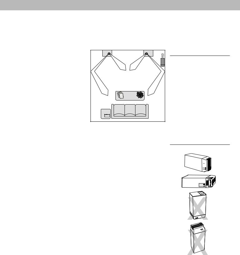
When you place your speakers according to the guidelines below, a combination of reflected and direct sound provides a good stereo image virtually everywhere in the room. You may experiment with the placement and orientation of the Jewel CubeTM speakers and Acoustimass® module to produce sound most pleasing to you.
To adjust your system for the characteristics of your listening room, see “Fine-tuning your system” on page 18.
Jewel Cube speakers
1.For the most lifelike sound, place the Jewel Cube speakers 6-12 feet (1.8-3.6 m) apart. They can be as close as 3 feet (1 m) or as far
apart as 15 feet (4.6 m).
2. Place the Jewel Cube speakers 6-12 inches (15-30 cm) from the surface behind them.
3. Direct one cube of each speaker toward the center of the room (Figure 2). Direct the other cube toward a side wall to create reflected sound.
Note:The Jewel Cube speakers are magnetically shielded so you can place them close to a TV without affecting picture quality.
Acoustimass module
Follow these guidelines to select a location for the Acoustimass module.
1.Place the Acoustimass module along a side wall near the front of the room, if possible (Figure 2). You can place the module along the same wall as the speakers, if more convenient.
2.Aim the round opening (port) along the wall, 2 feet (.6 m) from a corner (Figure 2). Avoid blocking the port.
3.Select a convenient location – under a table, behind a sofa. Do not allow furniture or drapes to block the ventilation openings on the module.
4.Place the Acoustimass module within reach of the audio input cable, speaker cables, and an electric outlet.
5.For proper ventilation, place the Acoustimass module on its long side, with the connectors facing the floor (Figure 3). Or place it on its largest side, with the bass and treble controls facing up. Do not place the module on either end.
6.Once you have selected a position for the Acoustimass module, place the four selfadhesive rubber feet near the corners of the bottom surface. On a bare floor, the rubber feet provide increased stability and protection from scratches.
7.For best bass performance, do not place the module midway between any two walls.
Note:To avoid interference with the TV picture, keep the Acoustimass module at least 18 inches (45 cm) from any TV.
Music center
Select a location for the music center.
1.Place the music center on a level surface and allow enough room to lift the door.
2.Make sure it is close enough to any additional sound sources (TV, VCR, etc.) to allow for cable length.
3.Keep the music center within 30 feet (9.1 m) of the Acoustimass module (the length of the audio input cable).
Figure 2
Recommended speaker locations
CAUTION:
Choose a stable and level surface for your Jewel Cube speakers. Vibration can cause the speakers to move, particularly on very smooth surfaces. For stability, peel off the backing from the rubber feet and center them in the matching shapes on the bottom of each speaker.
Figure 3
Acoustimass module positions
Preferred
position
Alternate
position
CAUTION:
Do not cover the ventilation openings of the Acoustimass module. The slots on the end provide ventilation for the built-in electronic circuitry, and should not be blocked.
6 |
October 29, 2001 |
AM178934_09_V.pdf |
Setting Up
Connect the speakers and Lifestyle® music center
Once you have selected locations for your speakers and music center, connect the system.
Connecting the Jewel CubeTM speakers to the Acoustimass® module
1.Insert the connector of each speaker cable fully into the jack on the rear of each speaker (Figure 4). Match the ridge of the connector to the notch at the top of the jack.
2.Connect each 20-foot (6.1 m) cable to the corresponding left or right green jack on the Acoustimass module. Speaker cables have green connectors at one end, with L (left) and R (right) molded into the connectors.
To lengthen the cable, connect speaker wire with male phono (RCA) plugs on each end to your supplied speaker cable. Use a female-to-female adapter (“barrel” connector). Or, splice in 18-gauge (.75 mm2) or thicker cord (connecting + to + and – to –). To purchase extension wire, see your dealer, electronics store, or call Bose® customer service.
Connecting the Acoustimass module to the Lifestyle® music center
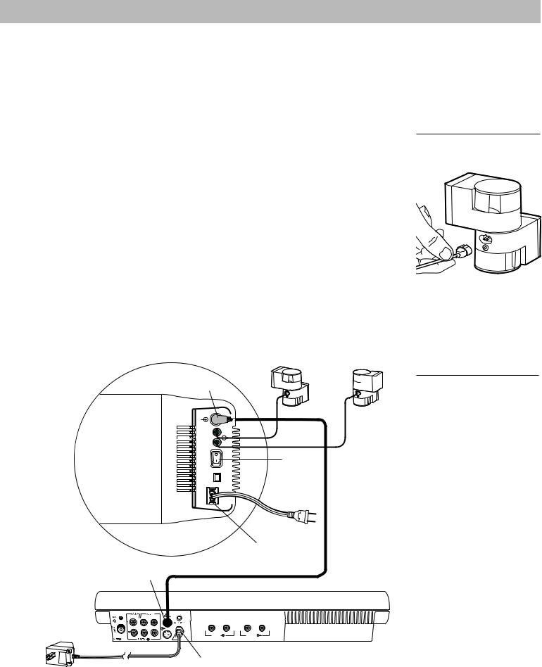
Connect the Acoustimass module to the music center with the audio input cable (Figure 5).
1.Plug the small black multi-pin connector into the jack marked SPEAKER ZONE 1 on the back of the music center.
2.Insert the right-angle multi-pin connector on the other end of the audio input cable into the AUDIO INPUT jack on the Acoustimass module. Align the connector at the angle shown in Figure 5.
Note:Be sure that each connector is inserted completely into each jack.
3.Extend the audio input cable as much as possible, since it includes an antenna for the remote control.
For information on connecting zone 2, see “Using two listening zones” on pages 19-20.
CAUTION:
Make sure all components of your system are unplugged from the AC power (mains) source before you begin connecting them.
Figure 4
Speaker cable connection to the Jewel Cube speaker
|
Right |
Left |
Right-angle connector |
speaker |
speaker |
into AUDIO INPUT |
R |
L |
AUDIO
INPUT
RIGHT
OUTPUTS
TO
CUBE
SPEAKERS
LEFT
ON |
Power |
OFF |
|
POWER |
|
|
switch |
Figure 5
Connecting the speakers and the music center
|
Power jack |
|
Black connector into |
Audio input cable |
|
SPEAKER ZONE 1 |
||
|
Power pack
L |
R L |
R |
TAPE IN |
|
TAPE OUT |
Power jack
AM178934_09_V.pdf |
October 29, 2001 |
7 |
Setting Up
Connecting the Acoustimass® module power cord
1.On a dual voltage Acoustimass module, the voltage selector switch is preset at the factory. Check to be sure it is set for the proper voltage (Figure 6). Use 115V for North America, and 230V for Europe and Australia. In Europe, use the adapter plug provided. If you are in doubt, contact your local electric utility for the appropriate voltage setting.
2.Plug the small end of the AC power (mains) cord into the module power jack.
Note:Do not plug the power cord into a power outlet until you complete all connections.
Connecting the music center power pack
The Lifestyle® music center comes with a 100V, 120V, 230V, or 240V power pack. See Figures 1 and 7. Dual voltage models include both the PS71 and PS72 power packs.
Use only the Bose® power pack model specified for your area:
• |
Model PS71, |
120V in North America |
• Model PS72, |
230V in Europe |
• |
Model PS73, |
100V in Japan |
• Model PS74, |
230V in UK or Singapore |
• Model PS77, 240V in Australia
1.Firmly insert the small connector on the end of the AC power (mains) pack cable into the AC POWER jack on the back of the Lifestyle® music center.
2.Make sure that the power pack reaches an AC power (mains) outlet.
Note:Do notplug the power pack into a power outlet until you complete all connections.
Figure 6
Dual voltage Acoustimass module: voltage selector switch settings
230 V
115 V
CAUTION:
Make sure the voltage selector switch is set correctly.
Figure 7
The AC power pack (model PS71 shown)
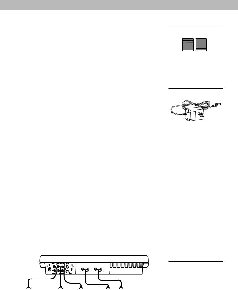
Other connections
Use standard audio cables to connect other components to your Lifestyle® music system, matching the red connector to R (right), white (or black) connector to L (left).
Video components
To play video sound through your Lifestyle® music system, connect the R and L fixed audio outputs of your stereo VCR, stereo TV, or laserdisc player to the music center VIDEO 1 or 2 jacks. See Figure 8. You can use a Y-adapter (available at electronics stores) to connect a mono source. However, the left and right speakers then play the same monaural sound.
Tape deck
To use an external tape recorder (analog audio cassette, analog open reel, digital audio tape, Digital Compact Cassette, or MiniDisc), connect the inputs (REC) of the tape deck to the music center TAPE OUT jacks. Connect the outputs (PLAY) from the tape deck to the music center TAPE IN jacks. See Figure 8.
Additional CD player or changer
To use an external CD player or changer, connect the outputs from the component to the music center AUX INPUT jacks. See Figure 8.
Turntable
To connect a turntable, you need a phono preamplifier (with RIAA equalization). Consult your dealer for the appropriate model.
Note:The Lifestyle® 20 music system cannot turn a connected component on or off.
L |
R L |
R |
TAPE IN |
|
TAPE OUT |
Other |
|
VCR, TV, |
|
VCR, TV, |
|
Outputs |
Inputs |
|
|
|
Tape |
|
|||
|
and/or |
|
and/or |
|
|
||
component |
|
|
|
deck |
|
||
|
laserdisc |
|
laserdisc |
|
|
||
|
|
|
|
|
|
||
|
|
|
|
|
|
|
|
CAUTION:
Be sure to use the correct power pack for your area. Using the wrong one may damage your music center.
Figure 8
Connecting other components
8 |
October 29, 2001 |
AM178934_09_V.pdf |
 Loading...