


®Direct/Reflecting VI Series ®901 ®Bose
The Bose® 901® Series VI Direct/Reflecting® Speaker System
Owner’s Guide
Brugervejledning
Bedienungsanleitung
Guía del usuario
Notice d’utilisation
Manuale d’istruzioni
Gebruiksaanwijzing
Bruksanvisning
System Speaker
English
Safety Information
WARNING: To reduce the risk of fire or electric shock, do not expose the system to rain or moisture .
WARNING: The apparatus shall not be exposed to dripping or splashing, and objects filled with liquids, such as vases, shall not be placed on the apparatus. As with any electronic products, use care not to spill liquids into any part of the system. Liquids can cause a failure and/or a fire hazard.
CAUTION |
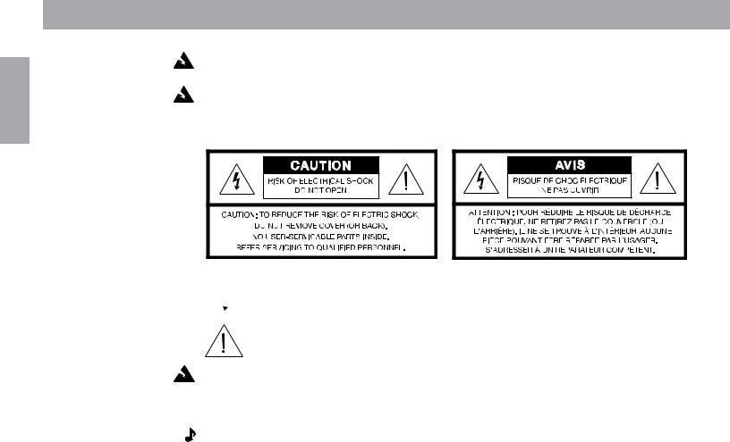
 These CAUTION marks are located on the bottom of your 901® active equalizer:
The lightning flash with arrowhead symbol, within an equilateral triangle, is intended to alert the user to the presence of uninsulated dangerous voltage within the system enclosure that may be of sufficient magnitude to constitute a risk of electric shock.
The exclamation point within an equilateral triangle, as marked on the system, is intended to alert the user to the presence of important operating and maintenance instructions in this owner’s guide.
CAUTION: To prevent electric shock, match wide blade of plug to wide slot, insert fully.
Note: Where the mains plug or appliance coupler is used as the disconnect device, such disconnect device shall remain readily operable.
Additional safety information
See the additional instructions on the Important Safety Information page enclosed with this owner’s guide.
Please read this owner’s guide
Please take the time to follow this owner’s guide carefully. It will help you set up and operate your system properly, and enjoy all of its advanced features. Save your owner’s guide for future reference.
For your records
Serial numbers are located on the bottom panel of each 901 speaker and on the back of the active equalizer.
Loudspeaker Serial Numbers:________________________________________________________
Active equalizer Serial Number:_ _____________________________________________________
Dealer name: ______________________________________________________________________
Dealer phone: ________________________ Purchase date: ______________________________
We suggest you keep your sales slip and warranty card together with this owner’s guide.
©2007 Bose Corporation. All rights reserved. Bose, Acoustimass, Lifestyle, Personal and Wave are registered trademarks of Bose Corporation.

Contents
Where to find…
Contents |
|
Where to find….............................................................................................................. 3 |
|
Warranty period............................................................................................................. |
3 |
Customer service........................................................................................................... |
3 |
Setting Up |
|
Before you begin............................................................................................................ |
4 |
Unpacking the cartons................................................................................................... |
4 |
System compatibility...................................................................................................... |
5 |
Choose the support for your speakers.......................................................................... |
6 |
Choosing the location for your speakers....................................................................... |
6 |
Speaker connections..................................................................................................... |
8 |
Equalizer connections.................................................................................................... |
9 |
Testing the speakers and equalizer.............................................................................. |
12 |
Using other equipment................................................................................................ |
13 |
Using your 901® Series VI speaker system |
|
Playing your speakers.................................................................................................. |
14 |
Adjusting the sound..................................................................................................... |
15 |
Equalizer compatibility................................................................................................. |
16 |
Connecting additional speakers.................................................................................. |
16 |
Maintaining Your 901 speaker system |
|
Cleaning your speakers............................................................................................... |
17 |
Troubleshooting........................................................................................................... |
17 |
Product Information |
|
Technical information................................................................................................... |
18 |
Accessories.................................................................................................................. |
18 |
Bose Corporation...................................................................................... |
inside back cover |
Warranty period
The Bose® 901 speakers and active equalizer are covered by a limited 5-year transferable warranty. Details of the warranty are provided on the warranty card that came with your system. Please fill out the information section on the card and mail it to Bose Corporation.
Customer service
For additional help in solving problems, contact Bose customer service. See the inside back cover for Bose customer service offices and phone numbers.
A free booklet is available: Guide to Optional System Connections for Bose 901® Direct/ Reflecting® Speaker Systems. Ask for part number 149393.
English
English
Setting Up
Before you begin
Thank you for purchasing the Bose® 901® Series VI Direct/Reflecting® speakers. They represent the best in Bose Corporation speaker design and engineering and will give you many years of listening pleasure.
The installation and operating principles of this system are significantly different from those of conventional speakers. To obtain the best possible performance and avoid problems, please take the time to read this guide.
CAUTION: You must have a Bose 901 active equalizer for a complete 901 speaker system. The use of 901 Series VI speakers without the 901 Series VI active equalizer will result in improper performance. The use of graphic or parametric equalizers, instead of the Bose 901 equalizer, will result in unsatisfactory performance.
Conventional graphic and parametric equalizers may be used in addition to, but not in place of the Bose 901 active equalizer. However, the use of such additional equalizers is not recommended since it will not improve system performance. For adequate performance you must use the 901 Series VI active equalizer with these speakers.
Unpacking the cartons
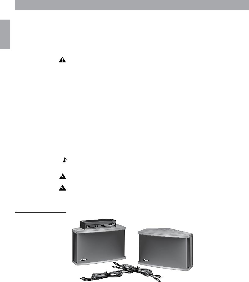
A complete Bose 901 Series VI speaker system consists of three matched components: two 901 Direct/Reflecting® speakers and a separate 901 Series VI active equalizer. Two cables are included to connect the active equalizer to your receiver or amplifier. The 901 speakers and equalizer are packed in three separate cartons. Carefully unpack your system, saving all packing materials for possible future use.
Inspect the speakers and equalizer. If any part appears damaged, do not attempt to use the system. Repack the speakers and equalizer in their original cartons and notify your authorized Bose dealer immediately.
Note: Now is a good time to record the serial numbers of each speaker and the active equalizer. Please write them on your warranty card and in the spaces provided on page 2. The serial numbers are located on the bottom of the 901 speakers and on the back of the equalizer.
Warning: Each speaker carton weighs over 35 lb (16 kg). Use good lifting practice to avoid injury.
Warning: To avoid danger of suffocation, keep the plastic bags out of the reach of children.
Figure 1
What comes in the three cartons:
• Two 901 speakers
• One 901 active equalizer
• Two equalizer cables

Setting Up
System Compatibility
Bose® 901® Series VI speakers and Series VI active equalizer work with your stereo components to produce a superb music system. The active equalizer is an integral part of the system and may be connected in a variety of ways, depending on the components you have. The two most common methods are described in this guide. Using different components may require different connection methods. More information is available by calling Bose Corporation. Ask for the free booklet, Guide to Optional System Connections for Bose 901 Direct/Reflecting® Speaker Systems, part number 149393.
Your 901 speakers are designed to work compatibly with receivers or amplifiers rated from 10 to 450 watts per channel. In this guide, the term receiver is used to refer to an integrated preamplifier and power amplifier (which may also contain an AM/FM tuner). The term amplifier is used to describe configurations involving separate preamplifier and amplifier components.
Most receivers have a TAPE MONITOR connection. The 901 active equalizer is most commonly connected to the tape monitor connections on the receiver. If you plan to connect a tape recorder, use the set of inputs and outputs located on the back of the 901 active equalizer marked TAPE RECORDER CONNECTIONS.
If you have recently purchased a home theater receiver, you may be considering using your 901 speakers for the front channels. Your home theater receiver must have accessible PRE AMP OUT/MAIN AMP IN connections for the front channels if you are to use your 901 speakers in this way. These may also be called the ADAPTER or SIGNAL PROCESSOR
connections.
Installation steps
Follow these steps, in the order below, to install your 901 Series VI speaker system.
1.Choose the best locations and support for the 901 speakers (page 6).
2.Connect the speakers to the amplifier or receiver (page 8).
3.Connect the 901 active equalizer to the amplifier or receiver using either the TAPE MONITOR or PRE AMP OUT/MAIN AMP IN connections (page 9).
4.Test the system to see that the audio signal is correctly processed by the active equalizer (page 12).
English
English
Setting Up
Choosing the location for your speakers
Choose locations for your 901® speakers that use the walls to best advantage by reflecting sound throughout the listening room. Refer to the drawing on page 7.
Guidelines for placement
Place the speakers along the same wall (see Figure 3):
•4 to 12 feet (1.2 – 3.6 m) apart, with the V-shaped rear of the speaker between 8 and 18 inches (20 – 45 cm) from the rear wall. Do not aim the V toward a corner.
•18 inches (45 cm) of clear space around the sides, top, and bottom of the speakers.
•at least 2 feet (60 cm) from sound-absorbent furnishings.
•18 to 48 inches (45 – 120 cm) from the side and rear walls.
•18 to 36 inches (45 – 91 cm) from the floor or ceiling. Do not place the speakers exactly halfway between floor and ceiling.
Within these guidelines, remember that the closer the speakers are placed to a reflective surface, like a wall, the more bass is reproduced.
Choose the support for your speakers
You may place 901 speakers on a table or shelf. You may also use Bose® floor pedestals, or suspend the speakers from your ceiling. Refer to Figure 3 on page 7.
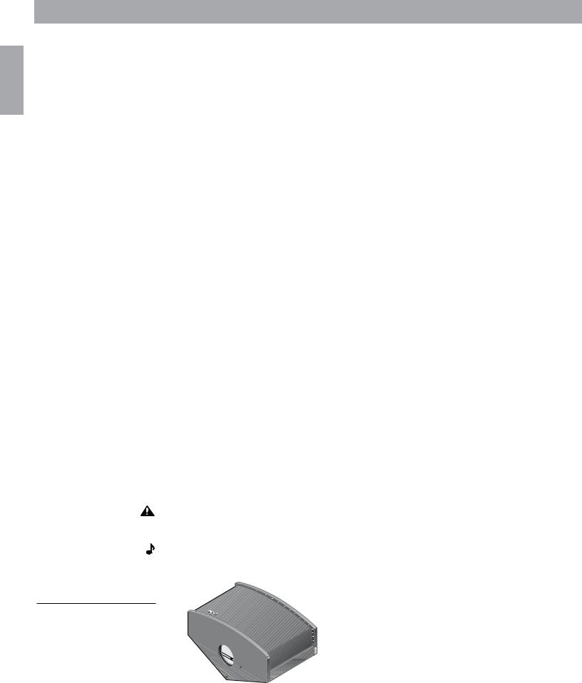
Figure 2
Pedestal (A) and ceiling mount
(B) pilot holes
To set the speakers on a table or shelf
Although each speaker weighs 35 lb (16 kg), a suitable shelf or table must be able to support 140 lb (64 kg). Keep an adequate distance between the speakers and the rear wall as listed in “Guidelines for placement” above.
To stand the speakers on the floor
Use only Bose pedestals (PS-6) as floor stands. They are designed to provide the proper support and are available through your authorized Bose dealer. Please read the pedestal attachment instructions before making any speaker connections. Four pilot holes on the bottom of each speaker (see Figure 2, hole set A) are pre-drilled for the purpose of anchoring the speaker to the pedestal.
To suspend the speakers from the ceiling
Use these guidelines to ensure safe suspension of your 901 speakers. Three steel support chains are recommended. We cannot specify the ceiling attachments. The type to use depends on the type of building construction.
CAUTION: Do not mount on surfaces that are not sturdy enough, or that have hazards concealed behind them, such as plumbing or electrical wire. If you are unsure of your ability to install these speakers, contact a qualified professional installer.
Note: The speakers hang in an inverted position, with the terminal connections facing up. Carefully rotate the Bose logo 180˚ (so it appears right side up) before hanging the speakers.
 B
B
 A
A
 A
A

 A
A  B
B 

B A
Setting Up
Hardware needed for ceiling suspension
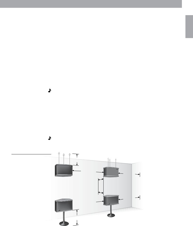
Figure 3
Mounting guidelines
•Screw hooks support the chains at the ceiling. They must have at least a #10 wood thread
with a shank diameter of at least 3⁄16 inch (4.5 mm). They should be long enough to go through any plasterboard and still have at least one inch (25 mm) of thread left to penetrate a wood beam. For a masonry ceiling: use only high-quality metal expansion masonry anchors that fit the thread of the ceiling hooks.
•Chain: diameter should be at least 5⁄32 inch (0.135 in. or 4 mm).
•Screw eyes with S hooks attach chains to the speaker and must have at least a #10 wood thread with a shank diameter of at least 3⁄16 inch (4.5 mm) or larger.
•All hardware (screw hooks, chain, screw eyes, S hooks) must have a manufacturer’s safeload rating of 40 lb (18 kg) or more.
General notes on ceiling suspension
•Suspend the speakers 18 – 36 inches (45 – 91 cm) from the ceiling; do not mount them flush to the ceiling.
•To ensure an accurate stereo image, the distance from the floor should be three to ten feet (1 – 3.5 m). Be sure the speakers are no less than 18 inches (45 cm) from the floor. Do not suspend the speakers exactly halfway between the floor and ceiling.
Note: If the speakers are more than 10 feet (3 m) from the floor, we suggest you lengthen the chain supporting the rear of the speaker. By doing this you will allow the rear of the speaker, housing eight of the nine drivers, to be angled slightly downward.
Step by step procedure for ceiling suspension
1.Ceiling: Anchor at least two screw hooks into a rigid structural ceiling support (beam, joist,
or masonry anchor). Drill pilot holes into wood using a 1⁄8 inch drill bit (3.7 mm), if necessary.
2.Speaker: Use the three pre-drilled pilot holes (see Figure 2 - hole set B) on the bottom of
each speaker. Use a 1⁄8 inch drill bit (3.7 mm) to enlarge the pilot holes to accept the #10 thread screw eyes. Drill to a depth of 1⁄2 inch (12 mm) in the speaker cabinet. Do not drill completely through the cabinet.
Note: Contact Bose® for more information on suspending speakers. See the inside back cover for phone numbers. For details on your specific ceiling construction, consult a qualified building contractor or professional installer.
18 – 36” (45 – 91 cm) |
|
|
4 – 12’ |
18 – 48” |
|
(1.2 – 3.6 m) |
||
(45 – 120 cm) |
||
|
8 – 18” |
– (20 – 45 cm) |
4 – 12’ |
18 – 48” |
(45 – 120 cm) |
 (1.2 – 3.6 m)
 18 – 36” (45 – 91 cm)
English
English
Setting Up
Speaker connections
With your speakers in their chosen locations, connect them to the receiver.
Choosing the wire
It is important to use the right thickness of speaker wire. For distances of up to 30 feet (9 m), 18 gauge (.075 mm2) 2-conductor wire works well. For distances greater than 30 feet (9 m), refer to the wire recommendations chart on page 18.
Note: To determine if this wire is suitable for use in a wall or under a floor, check your local building codes. You may want to contact a qualified electrical installer for this information.
Preparing the speaker wires
Examine the speaker wire. Note that it is actually a pair of insulated wires that may be gently pulled apart. The insulation around one wire is marked with a stripe, collar, rib, groove, or printing. Use the marked wire as positive (+) and the unmarked wire as negative (-). These wires correspond to the positive and negative terminals on the speaker and receiver.
Note: It may be difficult to distinguish wire markings. Inspect both wires carefully.
To prepare the ends of each wire:
1.Strip approximately 1/2 inch (12 mm) of insulation from both wires.
2.Twist the bare ends of each stranded wire, to prevent strands from touching across terminals.
Connecting the speakers
CAUTION: Before making any connections, turn off your receiver and unplug it from the AC (mains) power outlet. Not doing this may result in damage to your system.
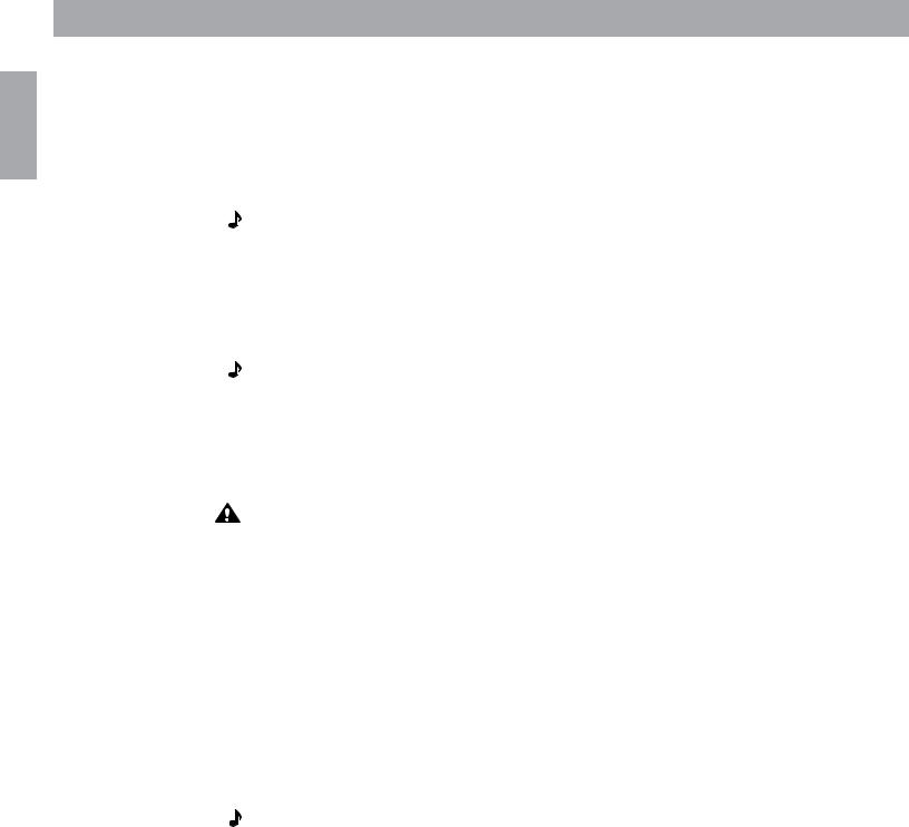
Speaker terminals are located on the bottom of each speaker. Unscrew the knurled nut on each terminal and remove one washer. Wrap one bare wire end around the terminal post. Then, replace the metal washer on the screw post and screw the knurled nut firmly back on.
1.Connect one wire pair to the right speaker (the one on your right as you face it).
a.Attach the marked wire at one end to the positive (+) terminal.
b.Attach the plain wire at that end to the negative (-) terminal.
2.Connect the other ends of the same wire pair to the RIGHT SPEAKER OUTPUT of your receiver.
a.Attach the marked wire to the positive (+) terminal.
b.Attach the plain wire to the negative (-) terminal.
3.Following the steps above, connect the second pair of wires to the left speaker and to the LEFT SPEAKER OUTPUT on the receiver.
Note: If your receiver offers a choice of output impedances, use the terminal marked 8 or 8 ohms.
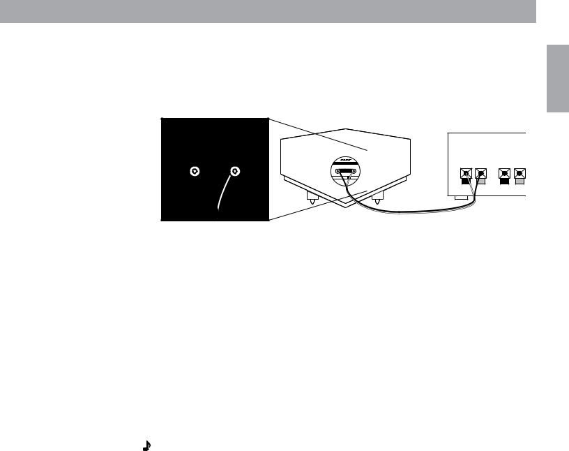
Figure 4
Connecting the speakers to the receiver
Setting Up
Checking the speaker connections
Make sure the terminal knurled nut is tightened down firmly. Any gap between the wire and terminal can cause heat build up. Check to be sure the wires are connected positive to positive (+ to +) and negative to negative (- to -). Make sure no loose strands of wire touch across terminals, which can cause short circuits.
Receiver
+ L – + R–
English
Equalizer Connections
There are two options for connecting the equalizer. Your choice depends on the type of receiver you own and whether you plan to use the system primarily for stereo or for home theater enjoyment.
Stereo/non-home theater use
(tape monitor connections)
The Bose® 901® active equalizer connects directly to your receiver through the tape monitor connection. If your receiver has more than one tape connection, use the second one (TAPE 2). To connect a tape deck, use the additional set of inputs and outputs located on the back of the 901 active equalizer marked TAPE RECORDER CONNECTIONS.
The TAPE MONITOR switch on the front of the receiver lets you switch the equalizer in and out of the signal path. This is important when you want to play conventional, non-equalized speakers or headphones attached to your receiver. See Using other equipment on page 13.
Note: If your receiver is designed for home theater use, it may not have a Tape Monitor switch. If not, you must use a PRE AMP OUT/MAIN AMP IN connection. This may also be called the ADAPTER or SIGNAL PROCESSOR connection. Refer to “Home theater use (PRE AMP OUT/ MAIN AMP IN)” on page 10 for instructions on how to connect for home theater use.
1.Disconnect any external tape deck or signal processor connected to the tape monitor connection .
2.Use the twin cable assemblies (with two connectors at each end) that are supplied with the equalizer. Use the red connector for the right (R) channel connections and the other connector for the left (L) channel connections.
English
Setting Up
3.Connect one end of a cable to the AMPLIFIER INPUT jacks on the 901® active equalizer.
a.Insert the first connector firmly into the INPUT jack marked R.
b.Insert the second connector into the INPUT jack marked L.
4.Connect the other end of the cable to the OUT or RECORD jacks on your receiver. These jacks may be marked TO INPUT, FROM INPUT, or REC.
a.Insert the first connector into the OUT or RECORD jack marked R.
b.Insert the second connector into the OUT or RECORD jack marked L.
5.Connect the second cable from the AMPLIFIER OUTPUT jacks on the 901 active equalizer to the IN or TAPE jacks on your receiver. These jacks may be marked PLAY, TO OUTPUT, FROM OUTPUT, or MONITOR.
6.Plug the power cord of the 901 active equalizer into one of the switched outlets on the receiver so that it will be powered when the receiver is switched on.
Figure 5
Connecting to the tape monitor connection
Home theater use
(PRE AMP OUT/MAIN AMP IN)
Use these instructions:
• for stereo-only operation if your receiver does not have a TAPE MONITOR connection.
• if you are using a surround sound receiver that has a section on the back marked PRE AMP OUT/MAIN AMP IN. The jacks may be labeled ADAPTER or SIGNAL PROCESSOR.
Note: If your receiver does not have this PRE AMP OUT/MAIN AMP IN section, the 901 speakers will not be usable in your home theater system.
1. The PRE AMP OUT/MAIN AMP IN jacks on your receiver are usually connected by small bars called horseshoe pins. Remove these pins. See Figure 6.
Figure 6
Removing horseshoe pins |
MAIN |
PRE |
|
AMP |
AMP |
|
IN |
OUT |
|
L |
R |
R |
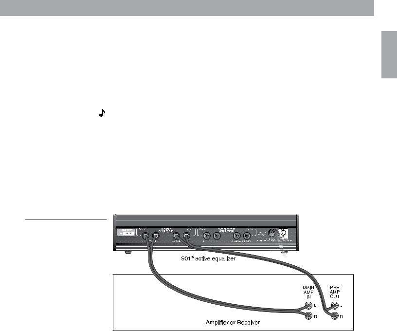
Amplifier or Receiver
10
Setting Up
2.Use the twin cable assemblies (with two connectors at each end) that are supplied with the equalizer. Use one connector for the right (R) channel connections and the other connector for the left (L) channel connections.
3.Connect the amplifier INPUT of the Bose® 901® active equalizer to the PRE AMP OUT jacks of the receiver or amplifier. Connect right channel to right channel and left to left.
4.Connect the amplifier OUTPUT of the active equalizer to the MAIN AMP IN jacks on the receiver or amplifier. Connect right channel to right channel and left to left.
5.Plug the power cord of the 901 active equalizer into one of the switched outlets on the receiver so that it will be powered when the receiver is switched on.
Note: This connection method does not allow you to connect a tape deck directly to the active equalizer. Connect it to the receiver instead.
Check to see that the 901 speakers are connected to the receiver MAIN or FRONT speaker jacks. In this way the 901 active equalizer signals will reach only the 901 speakers – the front channels of your home theater – and not any non-901 speakers used as center and surround channels.
Call Bose Corporation for assistance with the connection of additional speakers or signal processing equipment. Refer to the address information inside the back cover of this guide.
A free booklet is available (USA only): Guide to Optional System Connections for Bose 901 Direct/Reflecting® Speaker Systems. Ask for part number 149393.
Figure 7
Home theater receiver connections
English
11

English
Setting Up
Testing the speakers and equalizer
Choose the test method appropriate to your system:
To test the TAPE MONITOR connection
1.Turn off or disconnect any non-901 speakers or headphones that may be connected.
2.On the 901® active equalizer, press the MONITOR button IN to TAPE, and the BASS button OUT to position 1.
3.Set the MID-BASS and MID-TREBLE sliders to center positions.
4.Press your receiver or amplifier TAPE or TAPE MONITOR button to the OUT or NORMAL position so it is not selected.
5.Play music through your system. You should hear both speakers. Do not worry about the sound quality at this point. The equalizer is not yet engaged. If there is no sound from one or both speakers, check the receiver and speaker connections.
6.Move the receiver BALANCE control to the extreme left and then to the extreme right. This tests the left and right channel orientation. If the channels are reversed, check the connections.
To test the equalizer
You have now tested your speakers and their wiring. The following steps test the equalizer and its wiring:
1.With the speakers playing, press the receiver TAPE or TAPE MONITOR button IN, selecting the PLAY or MONITOR position. All sound should stop. If it does not, check your equalizer wiring. Be sure the 901 active equalizer MONITOR button is set to position 2 (TAPE).
2.Press the 901 active equalizer MONITOR button to SOURCE, position 1. The sound should return with full, natural sound characteristics. The system is now ready for use. If the sound does not return, and the equalizer power indicator is lit, the equalizer is probably connected incorrectly. Review equalizer connections.
To test the PRE AMP OUT/MAIN AMP IN connection
If you have connected the 901 active equalizer to the PRE AMP OUT/MAIN AMP IN connection, follow these instructions to test the speakers, equalizer, and wiring before connecting any other equipment to your system.
1.Turn off or disconnect any non-901 speakers or headphones that may be connected. If your system has a speaker selector switch, set it so that only the 901 speakers are connected to your power amplifier.
2.On the 901 active equalizer, press the MONITOR button OUT to SOURCE, and the BASS button OUT to position 1.
3.Set the MID-BASS and MID-TREBLE sliders to center positions.
4.Play music through your system. You should hear both speakers. If there is no sound from one or both speakers, check to see that the power indicator on the equalizer is lit, then check the receiver and speaker connections.
12
 Loading...