


T4B
IMPORTANT: IMPORTANT : IMPORTANTE:
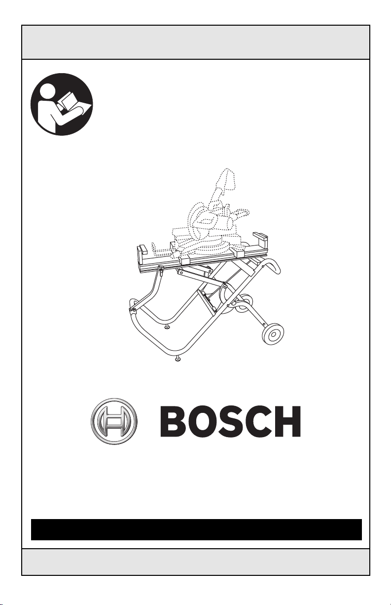
Read Before Using Lire avant usage Leer antes de usar
Operating/Safety Instructions
Consignes de fonctionnement/sécurité
Instrucciones de funcionamiento y seguridad
T4B
Call Toll Free
for Consumer
Information &
Service Locations
Pour tous renseignements et
pour obtenir la liste des centres
de service après-vente, appelez
le numéro gratuit :
Llame gratis para
obtener información
para el consumidor y
ubicaciones de servicio
1-877-BOSCH99 (1-877-267-2499) www.boschtools.com
For English Parlez-vous français? ¿Habla español?
See page 2 Voir page 13 Ver página 24

!&+*9>3897:(9.438+47".9*7!&<!9&3)
!
WARNING
*&) &3) :3)*789&3) &11
.38 9 7 : ( 9.438 Fai l u r e to
follow all instructions listed below and in your
miter saw manual m ay result i n serious
personal injury.
:1 1 > & 8 8 * 2 '1* &3) 9.,-9*3 &11 9-*
+&89*3*78 7*6:.7*) +47 9-.8 89&3) 184
7*2 * 2 '*7 9 4 4 ( ( & 8.43&1 1 > (- * ( 0 9 - *
89&3) &3) 2&0* 8:7* .9 .8 89.11 9.,-9 A
loose stand is unstable and may shift in use
and cause serious injury.
":7394418<.9(-4++&3)).8(433*(954<*7
'*+47* 24:39.3, 94 9-*89&3) Unintended
startup during assembly can cause injury.
*+47* 45*7&9.3, 2&0* 8:7* 9-* *39.7*
:3. 9 . 8 5 1 & ( * ) 4 3 & 8 4 1 .) +1&9 1*;*1
8:7+&(* Serious injury could occur if tool
with stand is unstable and tips.
*;*789&3)43944147.9889&3)47 :8*&8
1&))*7 47 8(&++41).3, Serious injury could
occur if the tool is tipped or the cutting tool is
acc i d e n tally con t a c t ed. Do no t s t o re
materials on or near the tool such that it is
necessary to stand on the tool or its stand to
reach them.
#8* 431> 48(- 7*51&(*2*39 5&798 Any
others may create a hazard.
The Miter Saw should be firmly mounted to
the stand per the instruction manual.
After mounting the Miter Saw to the stand,
align, position and balance the Miter Saw per
the instruction manual.
Before use, verify that all stand parts are free
from damage and/or deformity.
Bef o r e use, ver i f y t hat all p a r t s or
com p o n e nts of the stand are properl y
installed.
When mounting the Miter Saw to the stand,
make sure that the tool mount handles are in
the “UNLOCK” position, so the tool mount will
engage with the main rail. Be sure to hold the
saw until it is s ecured to preven t it from
falling off the main rail. Handles should then
be l o c k e d. (See p a g e 10 for d e t a iled
instructions.)
Wh en remo ving the Mite r S aw from the
stand, pull the tool mount handles until they
rotate to the “UNLOCK” position. Hold the
Miter Saw firmly to prevent the saw from
falling off the main rail. Carefully remove the
Mit e r Saw. ( S ee pa g e 10 fo r de t a i l e d
instructions.)
Do not modify the stand in any manner or
use the stand for any purpose other than is
stated in these instructions.
Because cut material may cause the stand to
become unb alanced, alwa ys be sure the
material is supported properly. Also, if the
piece being cut is placed far beyond the work
support, the opposite side may suddenly be
lifted up due to weight imbalance. To prevent
this from occurring, hold the opposite side
firmly before cutting.
"-.8"7&;.9> .8*.9*7!&<!9&3).8)*8.,3*)94'*:8*)
<.9-9-*+4114<.3,2.9*78&<8
Other units may be compatible, but have not been verified for use with the T4B system.
48(-
42 12, 4 212 L, 441 0, 441 0L,
44 1 2 , 44 0 5, 5412L, 391 2 ,
3915, 3918, 3924
*19&
36 - 2 5 5, 3 6 - 255L, 3 6 -240,
MS450
*$&19
DW 7 12, DW70 5 S, DW70 3 ,
DW 7 0 8 , DW706 , D W 718,
DW715, DW716, DW709
&0.9&
LS 1 2 1 4, L S 1 221, LS 1013,
LS1212, MS1214F
.1<&:0**
6497-6
-2-
.),.)
MS1065LZ, MS1250LZ
>4'.
TS1353DXL, TS1341, TS1552
7*88*2'1>
You have purchased a Bosch T4B Miter Saw
Stand, designed for job site use. This unit
se ts up and fol ds quic kly, an d i s e asil y
loaded or unloaded by one person into a
truck.
Phi l l i p s screwdri v e r , 10 MM op en end
wrench, 13 MM open end wrench, 17 MM
open end wrench, and adjustable wrench.
Sort out and account for all parts to make
sure that you have all necessary materials to
assemble your stand. Do not discard packing
material until all parts are accounted for.
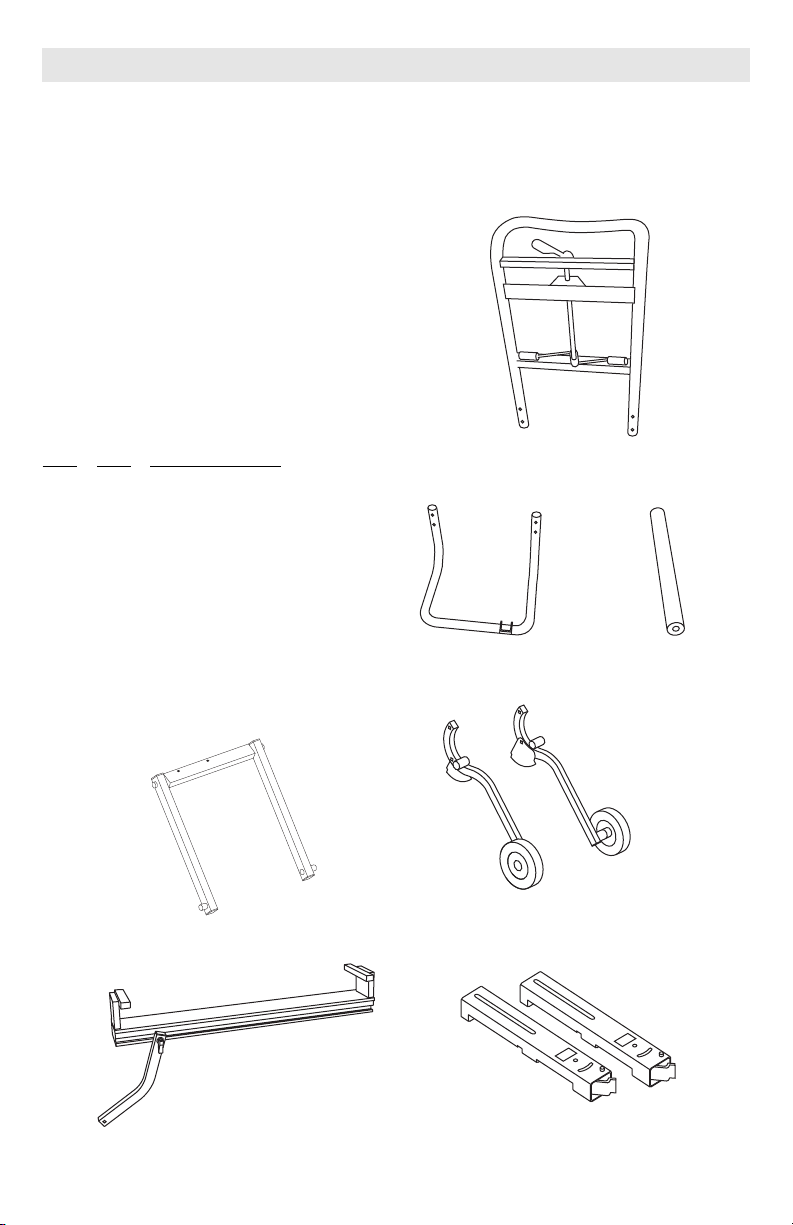
9*2
A (1) Main Frame
B (1) Base Tube
C (1) Kick Bar
D (1) Right Wheel/Leg Assembly
E (1) Left Wheel/Leg Assembly
F (1) Support Link Assembly
G (1) Rail Assembly/Support Leg
H (2) Tool Mount Assemblies
"! #
%#!!"!
" !$!"
"" !$!"
""!
9> &79*8(7.59.43
-3-
!"!!% $
5&(0&,*).343*'&,
9> &79*8(7.59.43
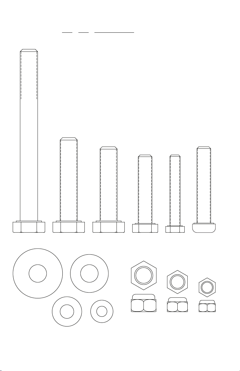
9*2
I410mm x 100mm Hex Head Bolts
J110mm x 55mm Hex Head Bolt
K210mm x 50 mm Nylock Hex Head Bolts
L48mm x 45mm Hex Head Bolts
M86mm x 45mm Hex Head Bolts
N48mm x 50 mm Phillips Head Screws
O210mm x 29mm OD Flat Washers
P 14 10mm Flat Washers
Q48mm Flat Washers
R86mm Flat Washers
S510mm Lock Nuts
T48mm Lock Nuts
U86mm Lock Nuts
!
"
#
-4-
88*2'1>
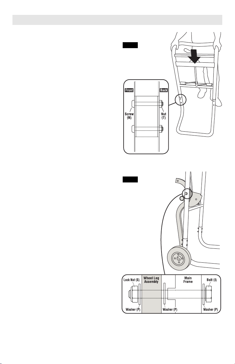
!9*5
99&(-&.37&2*&3)&8*":'*
1. Position base tube on a flat surface as
shown in figure 1.
2. Insert ends of main frame into the base
tube and push downward as far as it will
go.
3. Insert four (4) 8 mm x 50 mm Phillips Head
Screws (N) through the holes of the main
frame and base tube, and securely tighten
with four (4) 8 mm lock nuts (T) as shown.
FIG. 1
!9*5
99&(-$-**1*,88*2'1.*8
1. Locate the right wheel/leg assembly (see
“R” sticker) and position on right side of
main frame/base tube assembly as shown
in figure 2.
2. Place one (1) 10mm flat washer (P) onto
one (1) 10 mm x 100 mm bolt (I) and insert
through main frame.
3. Place another (1) 10 mm flat washer (P)
on bolt between wheel/leg assembly and
main frame.
4. Insert bolt thro u g h r i g h t w heel/leg
assembly, place one (1) 10 mm flat washer
(P), and loosely tighten with one (1) 10 mm
lock nut (S).
49* Do not over-tighten lock nut. These
parts need to freely rotate for stand to
operate properly.
Repeat procedure on left side.
FIG. 2
-5-
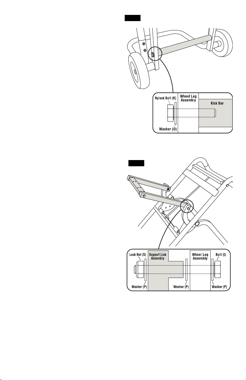
!9*5
99&(-.(0&7
1. Locate the kick bar and position it between
the left and right wheel/leg assemblies as
shown in figure 3.
2. Place on e (1 ) 1 0 mm x 29 mm O D f l at
washer (O) onto one (1) 10mm x 50mm
Nyl o c k h e x he a d b o l t ( K ) . I n s ert b olt
thr o u g h the wheel/leg assembl y and
thread it into the the kick bar and securely
tighten.
Repeat this procedure on other side.
FIG. 3
!9*5
99&(-!:55479.3088*2'1>
1. Unfold stand from vertical position:
With one hand on the handle, foot on the
kick bar, pull back slightly and rotate the
release lever to disengage the locking pins.
With both hands on the handle, pull back,
push down, and lower the stand until it
locks in position.
2. Loc ate the sup port l ink assembly a nd
assemble as shown in figure 4. Note the
“R” and “L” stickers for proper orientation.
3. Place one (1) 10mm flat washer (P) onto
one (1) 10mm x 100mm bolt (I).
4. Insert bolt through wheel/leg assembly and
place one (1) 10mm flat washer (P) on bolt
bet w e e n wheel / l e g and s u p port li n k
assemblies.
5. Insert bolt through support link assembly,
place one (1) 10mm flat washer (P), and
loosely tighten with one (1) 10mm lock nut
(S).
49* Do not over-tighten lock nut. These
parts need to freely rotate for stand to
operate properly.
Repeat this procedure for the opposite side.
FIG. 4
-6-

!9*5
99&(- &.188*2'1>
1. Locate the rail assembly and assemble as
shown in figure 5.
2. Fold stand upright: Rotate release lever
do wn to clea r lock ing pin s. Wit h b oth
hands on the handle, pull up and push
forward on the stand until it locks into the
upright position (see page 9).
3. Cut the strap restraining the support leg in
place. Make sure the support leg is sitting
on top of t h e b a s e tu b e u n t i l t h e ra i l
assembly is fully secured.
4. Place one (1) 6mm flat washer (R) onto
one (1) 6mm x 45mm bolt (M).
5. Raise the rail assembly and align it with
the holes in the long rail support. Prior to
fastening the rail assembly, make sure the
fastener access window on the long rail
support and support link face down when
the stand is in its horizontal position.
6. Insert one (1) 6mm x 45mm bolt (M) with
6mm flat washer (R) through the holes of
the long rail support and the rail. Loosely
tighten with one (1) 6mm lock nut (U).
7. Repeat step 6 of this procedure for the
remaining three (3) hole locations in the
long rail s uppor t and t he four (4) hole
locations in the support link assembly.
8. Securely tighten all eight (8) bolts.
FIG. 5
!# "
!9*5
!*(:7*!:55479*,
1. Loc ate the sup por t leg an d secure as
shown in figure 6.
2. Place one (1) 10mm flat washer (P) onto
one (1) 10mm x 55mm Hex Head bolt (J).
3. Align the support leg with its hinge built
into the base tube.
4. Insert one (1) 10mm x 55mm Hex Head
bolt (J) with 10mm flat washer (P) through
the support leg hinge and support leg.
Place one (1) 10mm flat washer (P) and
tighten with one (1) 10mm lock nut (S).
49* Do not over-tighten lock nut. These
parts need to freely rotate for stand to
operate properly.
FIG. 6
-7-
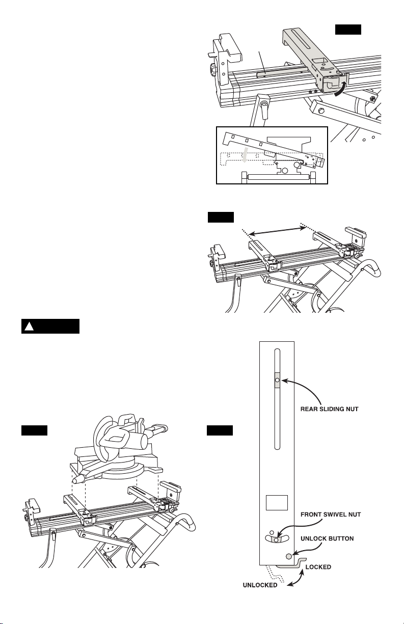
4:39.3,.9*7!&<94!9&3)
49* U nfold stand to horizont al position
bef o r e mount i n g saw. ( S e e pag e 9 for
instructions.)
1. Locate the tool mount assemblies, place
one (1) on the rail agai nst the red tool
mount secondary stop, and push the red
release lever to the locked position, as
shown in figures 7 & 10.
2. Measure the width of the rear mounting
holes of the miter saw, place the other tool
mount on the rail with the same distance
apart as shown in figure 8, and push the
release lever to the locked position.
3. Place miter saw on top of the tool mounts,
figure 9, align mounting holes by adjusting
rear sliding nuts and front swivel nuts,
figure 10. Be sure the front of the saw is
aligned to the front of both tool mounts.
4. Place one (1) 8mm flat washer (Q) onto
one (1) 8mm x 45 m m bo l t (L ) , in s e rt
through miter saw base and loosely tighten
into tool mount.
5. Repeat step 4 of this procedure for the
remaining three (3) hole locations.
6. Securely tighten all four (4) bolts.
!
WARNING
Mak e s u r e t h e saw is
properly oriented as shown
in the diagram to prevent any tipping hazard.
Look for the yellow warning decal on the
stand that states “operate saw from this side
only.”
FIG. 8
Tool Mount
Secondary
Stop
FIG. 7
FIG. 9 FIG. 10
-8-
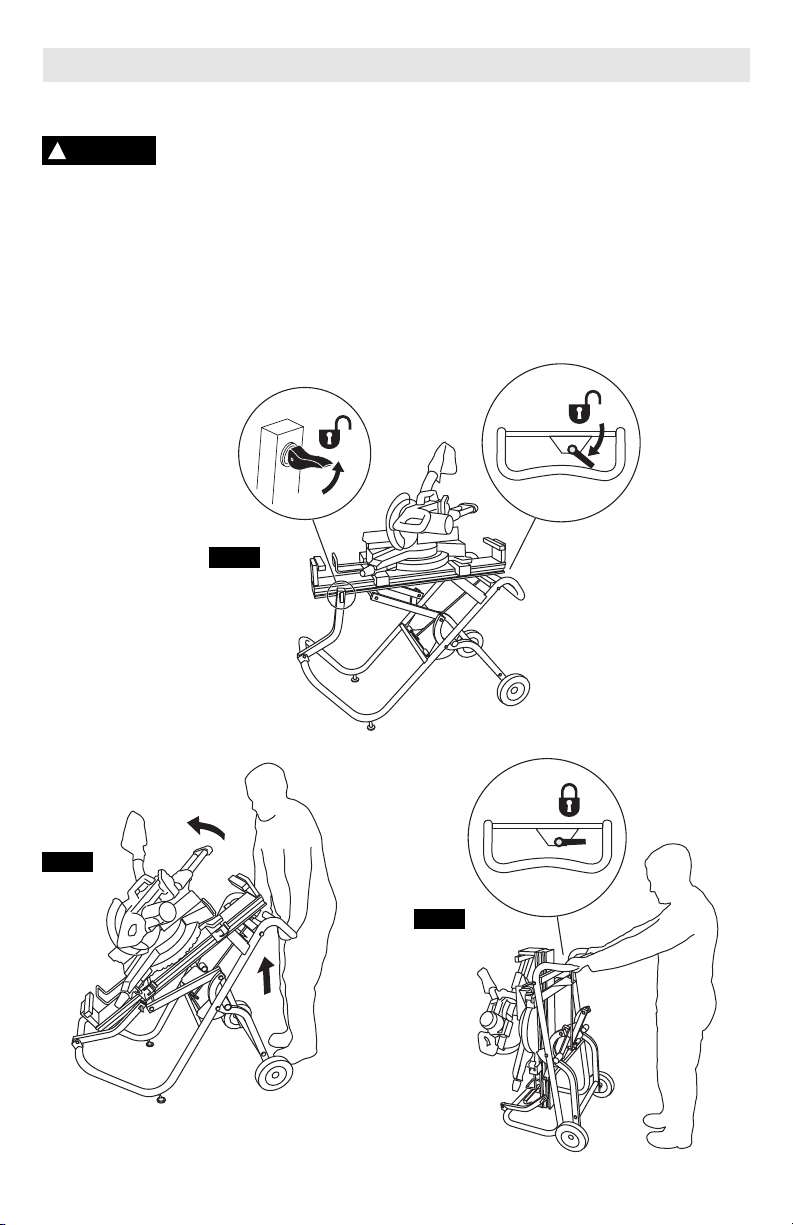
5*7&9.3,3897:(9.438
41)!9&3)
!
WARNING
unfolding the stand.
1. Unlock support leg cam lock, figure 11.
2. Rotate release lever down to clear locking
pins, figure 11.
3. With both hands on the handle, pull up and
push forward on the stand, figure 12, until
it locks in the upright position, figure 13.
Keep fingers clear of hinge
poi n t s when f o l d ing or
FIG. 11
#3+41)!9&3)
1. With one hand on the handle, foot on the
kick bar, pull back slightly and rotate the
release lever to disengage the locking pins.
2. With both hands on the handle, pull back,
push down, and lower the stand until it
locks in position.
3. Lock down cam lock support leg.
FIG. 12
FIG. 13
-9-
*24;*!&<742!9&3)
<.9-944124:398&99&(-*)
1. Pres s t h e u nloc k b u tton on ea ch tool
mount and open the release lever to the
unlocked position (see fig. 10, p8).
2. Locate the carry handles at the base of the
saw. Place one hand on the saw base
handle and the second on the saw’s top
handle, as shown in figure 14. Holding
tightly, tilt the saw (with the tool mounts
still attached) toward yourself and lift it
from the stand.
99&(-9-*!&<949-*!9&3)
<.9-944124:398&99&(-*)
1. Make sure the tool mount release levers
on each mou n t ar e in th e op e n an d
unlocked position (see fig. 10, p8).
2. Locate the carry handles at the base of the
saw. Place one hand on the saw base
handle and the second on the saw’s top
handle. Lift the saw to the rail assembly.
3. Line up the left tool mount next to the red
secondary stop on the rail assembly as
close as possible.
4. Tilt the saw until the front jaws of both tool
mounts are engaged to the rail. With both
hands on the saw handles, guide the saw
back to its level position on the rail (see
fig. 7, p8).
5. Push the release lever on each tool mount
to the locked position.
!
WARNING
position before operating or transporting the
saw.
Be sure b o t h to o l mou n t
lev e r s ar e in th e lo c k e d
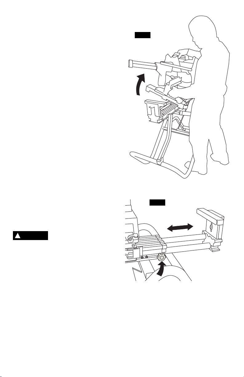
=5&38.43 &.1)/:892*39
1. Loosen the locking knob located along the
side of the rail assembly, a s shown i n
figure 15.
2. Extend expansion rail to desired length
and r e tighten l ocking k n ob bef o r e
beginning work.
3. Repeat process for opposite side.
FIG. 14
FIG. 15
-10-
$470*.,-9!:55479)/:892*39
1. Loosen the locking knob located at the end
of the expansion rail, as shown in figure
16, and raise the work height support so it
is level with the table top of the attached
miter saw.
2. Retighten knob and repeat on opposite
side.
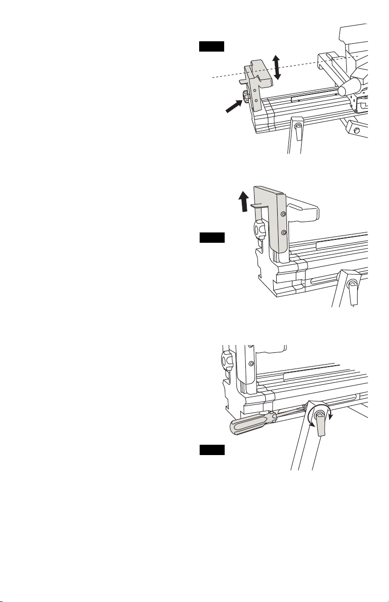
*5*9.9.;*!945)/:892*39
To raise the repetitive stop: Lift up and in
place as shown in figure 17.
To stow: Push the repetitive stop in toward
the rail assembly and down.
Repeat on opposite side.
&2*;*7)/:892*39
In the event the cam lever for the support leg
lo o sens over ti m e, t ighte n as sh o wn i n
figure 18.
1. Place th e cam lev e r in the “ L o c k ed”
position.
2. Insert a flat head screw driver between the
bottom of M8 Nylock nut and the rail.
3. Rotate the cam lever clockwise to tighten
and counter-clockwise to loosen in order to
achieve the appropriate feel and stability of
the support leg.
FIG. 16
FIG. 17
-11-
FIG. 18
 Loading...