


 Loading...
IP Camera 200 Series
NDC-265-P
en Installation and Operation Manual

IP Camera 200 Series |
Table of Contents | en 3 |
|
|
|
|
Table of Contents |
|
|
|
|
|
1 |
Safety |
7 |
1.1 |
Safety precautions |
7 |
1.2 |
Important safety instructions |
8 |
1.3 |
FCC & ICES compliance |
9 |
1.4 |
UL certification |
10 |
1.5 |
Bosch notices |
10 |
1.6 |
Copyrights |
11 |
|
|
|
2 |
Introduction |
13 |
2.1 |
Features |
13 |
2.2 |
Unpacking |
14 |
|
|
|
3 |
Installation |
15 |
3.1 |
Disassembly |
15 |
3.2 |
MicroSDHC card |
16 |
3.3 |
Network (and power) connector |
17 |
3.4 |
Power connection |
18 |
3.4.1 |
DC power connection |
18 |
3.5 |
I/O connector |
19 |
3.6 |
Audio connectors |
20 |
3.7 |
Mounting |
21 |
3.8 |
Camera set-up |
22 |
3.8.1 |
Camera positioning |
22 |
3.8.2 |
Focal length and focus |
24 |
3.9 |
Resetting the camera |
25 |
3.10 |
Closing the unit |
25 |
|
|
|
4 |
Browser connection |
27 |
4.1 |
System requirements |
27 |
4.2 |
Establishing the connection |
27 |
4.2.1 |
Password protection in camera |
28 |
4.3 |
Protected network |
28 |
4.4 |
Connection established |
29 |
Bosch Security Systems |
Installation and Operation Manual |
AR18-10-B012 | v1.5 | 2011.01 |

4 en | Table of Contents |
IP Camera 200 Series |
|
|
|
|
4.4.1 |
LIVEPAGE |
29 |
4.4.2 |
RECORDINGS |
29 |
4.4.3 |
SETTINGS |
29 |
|
|
|
5 |
Basic Mode |
31 |
5.1 |
Basic Mode menu tree |
31 |
5.2 |
Device Access |
32 |
5.2.1 |
Camera name |
32 |
5.2.2 |
Password |
32 |
5.3 |
Date/Time |
33 |
5.4 |
Network |
34 |
5.5 |
Encoder |
35 |
5.6 |
Audio |
35 |
5.7 |
Recording |
35 |
5.7.1 |
Storage medium |
35 |
5.8 |
System Overview |
35 |
|
|
|
6 |
Advanced Mode |
37 |
6.1 |
Advanced Mode menu tree |
37 |
6.2 |
General |
38 |
6.2.1 |
Identification |
38 |
6.2.2 |
Password |
38 |
6.2.3 |
Date/Time |
40 |
6.2.4 |
Display Stamping |
41 |
6.3 |
Web Interface |
43 |
6.3.1 |
Appearance |
43 |
6.3.2 |
LIVEPAGE Functions |
44 |
6.3.3 |
Logging |
45 |
6.4 |
Camera |
46 |
6.4.1 |
Picture Settings |
46 |
6.4.2 |
Encoder Profile |
48 |
6.4.3 |
Encoder Streams |
52 |
6.4.4 |
Audio |
53 |
6.4.5 |
Installer Menu |
54 |
6.5 |
Recording |
55 |
6.5.1 |
Storage Management |
56 |
AR18-10-B012 | v1.5 | 2011.01 |
Installation and Operation Manual |
Bosch Security Systems |

IP Camera 200 Series |
Table of Contents | en 5 |
|
|
|
|
6.5.2 |
Recording Profiles |
59 |
6.5.3 |
Retention Time |
61 |
6.5.4 |
Recording Scheduler |
62 |
6.5.5 |
Recording Status |
63 |
6.6 |
Alarm |
64 |
6.6.1 |
Alarm Connections |
64 |
6.6.2 |
Video Content Analyses (VCA) |
67 |
6.6.3 |
VCA configurationProfiles |
68 |
6.6.4 |
VCA configuration - Scheduled |
74 |
6.6.5 |
VCA configuration - Event triggered |
76 |
6.6.6 |
Audio Alarm |
77 |
6.6.7 |
Alarm E-Mail |
78 |
6.7 |
Interfaces |
80 |
6.7.1 |
Alarm input |
80 |
6.7.2 |
Relay |
80 |
6.8 |
Network |
82 |
6.8.1 |
Network Access |
82 |
6.8.2 |
Advanced |
86 |
6.8.3 |
Multicast |
87 |
6.8.4 |
FTP Posting |
89 |
6.9 |
Service |
90 |
6.9.1 |
Maintenance |
90 |
6.9.2 |
System Overview |
92 |
|
|
|
7 |
Operation via the browser |
93 |
7.1 |
Livepage |
93 |
7.1.1 |
Processor load |
93 |
7.1.2 |
Image selection |
94 |
7.1.3 |
Digital I/O |
95 |
7.1.4 |
System Log / Event Log |
95 |
7.1.5 |
Saving snapshots |
96 |
7.1.6 |
Recording video sequences |
96 |
7.1.7 |
Running recording program |
96 |
7.1.8 |
Audio communication |
96 |
7.2 |
Recordings page |
98 |
7.2.1 |
Controlling playback |
98 |
Bosch Security Systems |
Installation and Operation Manual |
AR18-10-B012 | v1.5 | 2011.01 |

6 en | Table of Contents |
IP Camera 200 Series |
|
|
|
|
|
|
|
8 |
Troubleshooting |
101 |
8.1 |
LED indicators |
101 |
8.2 |
Resolving problems |
101 |
8.3 |
Customer service |
101 |
|
|
|
9 |
Maintenance |
103 |
9.1 |
Repairs |
103 |
9.1.1 |
Transfer and disposal |
103 |
|
|
|
10 |
Technical Data |
105 |
10.1 |
Specifications |
105 |
10.1.1 |
Accessories |
106 |
AR18-10-B012 | v1.5 | 2011.01 |
Installation and Operation Manual |
Bosch Security Systems |
IP Camera 200 Series |
Safety | en |
7 |
|
|
|
1Safety
1.1Safety precautions
DANGER!
High risk: This symbol indicates an imminently hazardous situation such as "Dangerous Voltage" inside the product. If not avoided, this will result in an electrical shock, serious bodily injury, or death.
WARNING!
Medium risk: Indicates a potentially hazardous situation.
If not avoided, this could result in minor or moderate bodily injury.
CAUTION!
Low risk: Indicates a potentially hazardous situation.
If not avoided, this could result in property damage or risk of damage to the device.
Bosch Security Systems |
Installation and Operation Manual |
AR18-10-B012 | v1.5 | 2011.01 |

8 en | Safety |
IP Camera 200 Series |
|
|
1.2Important safety instructions
Read, follow, and retain for future reference all of the following safety instructions. Heed all warnings on the unit and in the operating instructions before operating the unit.
1.Cleaning - Generally, using a dry cloth for cleaning is sufficient but a moist, fluff-free cloth or leather shammy may also be used. Do not use liquid cleaners or aerosol cleaners.
2.Heat Sources - Do not install the unit near any heat sources such as radiators, heaters, stoves, or other equipment (including amplifiers) that produce heat.
3.Water - Never spill liquid of any kind on the unit.
4.Lightning - Take precautions to protect the unit from power and lightning surges.
5.Controls adjustment - Adjust only those controls specified in the operating instructions. Improper adjustment of other controls may cause damage to the unit.
6.Power sources - Operate the unit only from the type of power source indicated on the label.
7.Servicing - Unless qualified, do not attempt to service this unit yourself. Refer all servicing to qualified service personnel.
8.Replacement parts - Use only replacement parts specified by the manufacturer.
9.Installation - Install in accordance with the manufacturer's instructions and in accordance with applicable local codes.
10.Attachments, changes or modifications - Only use attachments/accessories specified by the manufacturer. Any change or modification of the equipment, not expressly approved by Bosch, could void the warranty or, in the case of an authorization agreement, authority to operate the equipment.
AR18-10-B012 | v1.5 | 2011.01 |
Installation and Operation Manual |
Bosch Security Systems |

IP Camera 200 Series |
Safety | en |
9 |
|
|
|
1.3FCC & ICES compliance
FCC & ICES Information
(U.S.A. and Canadian Models Only)
This equipment has been tested and found to comply with the limits for a Class B digital device, pursuant to part 15 of the FCC Rules. These limits are designed to provide reasonable protection against harmful interference in a residential installation. This equipment generates, uses, and can radiate radio frequency energy and, if not installed and used in accordance with the instructions, may cause harmful interference to radio communications. However, there is no guarantee that interference will not occur in a particular installation. If this equipment does cause harmful interference to radio or television reception, which can be determined by turning the equipment off and on, the user is encouraged to try to correct the interference by one or more of the following measures:
–reorient or relocate the receiving antenna;
–increase the separation between the equipment and receiver;
–connect the equipment into an outlet on a circuit different from that to which the receiver is connected;
–consult the dealer or an experienced radio/TV technician
for help.
Intentional or unintentional modifications, not expressly approved by the party responsible for compliance, shall not be made. Any such modifications could void the user's authority to operate the equipment. If necessary, the user should consult the dealer or an experienced radio/television technician for corrective action.
The user may find the following booklet, prepared by the Federal Communications Commission, helpful: How to Identify and Resolve Radio-TV Interference Problems. This booklet is available from the U.S. Government Printing Office, Washington, DC 20402, Stock No. 004-000-00345-4.
Bosch Security Systems |
Installation and Operation Manual |
AR18-10-B012 | v1.5 | 2011.01 |
10 en | Safety |
IP Camera 200 Series |
|
|
1.4UL certification
Disclaimer
Underwriter Laboratories Inc. ("UL") has not tested the performance or reliability of the security or signaling aspects of this product. UL has only tested fire, shock and/or casualty hazards as outlined in UL's Standard(s) for Safety for Closed Circuit Television Equipment, UL 2044. UL Certification does not cover the performance or reliability of the security or signaling aspects of this product.
UL MAKES NO REPRESENTATIONS, WARRANTIES, OR CERTIFICATIONS WHATSOEVER REGARDING THE PERFORMANCE OR RELIABILITY OF ANY SECURITY OR SIGNALING RELATED FUNCTIONS OF THIS PRODUCT.
1.5Bosch notices
Disposal - Your Bosch product was developed and manufactured with high-quality material and components that can be recycled and reused. This symbol means that electronic and electrical appliances, which have reached the end of their working life, must be collected and disposed of separately from household waste material. Separate collecting systems are usually in place for disused electronic and electrical products. Please dispose of these devices at an environmentally compatible recycling facility, per European Directive 2002/96/EC
More information
For more information please contact the nearest Bosch Security Systems location or visit www.boschsecurity.com
AR18-10-B012 | v1.5 | 2011.01 |
Installation and Operation Manual |
Bosch Security Systems |
IP Camera 200 Series |
Safety | en 11 |
|
|
1.6Copyrights
The firmware 4.1 uses the fonts "Adobe-Helvetica-Bold-R- Normal--24-240-75-75-P-138-ISO10646-1" and "Adobe- Helvetica-Bold-R-Normal--12-120-75-75-P-70-ISO10646-1" under the following copyright:
Copyright 1984-1989, 1994 Adobe Systems Incorporated. Copyright 1988, 1994 Digital Equipment Corporation. Permission to use, copy, modify, distribute and sell this software and its documentation for any purpose and without fee is hereby granted, provided that the above copyright notices appear in all copies and that both those copyright notices and this permission notice appear in supporting documentation, and that the names of Adobe Systems and Digital Equipment Corporation not be used in advertising or publicity pertaining to distribution of the software without specific, written prior permission.
This software is based in part on the work of the Independent JPEG Group.
Bosch Security Systems |
Installation and Operation Manual |
AR18-10-B012 | v1.5 | 2011.01 |

12 en | Safety |
IP Camera 200 Series |
|
|
AR18-10-B012 | v1.5 | 2011.01 |
Installation and Operation Manual |
Bosch Security Systems |

IP Camera 200 Series |
Introduction | en 13 |
|
|
2Introduction
2.1Features
This HD 720p IP camera is a ready-to-use, complete network video surveillance system inside a compact camera. The camera offers a cost-effective solution for a broad range of applications. It uses H.264 compression technology to give clear images reducing bandwidth and storage.The camera can be used as a stand-alone video surveillance system with no additional equipment or it can easily integrate with the Bosch DVR 700 Series recorders.
Features include:
–MicroSD/SDHC card slot supports edge recording up to 32 GB
–Tri-streaming: Two H.264 streams and one M-JPEG stream
–HD 720p Progressive scan for sharp images of moving objects
–Two-way audio and audio alarm
–Power over Ethernet (IEEE 802.3af compliant)
–Tamper and motion detection
–Conforms to the ONVIF standard for wide compatibility
Bosch Security Systems |
Installation and Operation Manual |
AR18-10-B012 | v1.5 | 2011.01 |
14 en | Introduction |
IP Camera 200 Series |
|
|
2.2Unpacking
Unpack carefully and handle the equipment with care.
The packaging contains:
–IP camera with lens
–Universal power supply with US, EU and UK plug
–Installation paper sticker
–Quick installation guide
–CD ROM
–Bosch Video Client
–Documentation
–Tools
If equipment has been damaged during shipment, repack it in the original packaging and notify the shipping agent or supplier.
WARNING!
Installation should only be performed by qualified service personnel in accordance with the National Electrical Code or applicable local codes.
CAUTION!
The camera module is a sensitive device and must be handled carefully.
AR18-10-B012 | v1.5 | 2011.01 |
Installation and Operation Manual |
Bosch Security Systems |
IP Camera 200 Series |
Installation | en 15 |
|
|
3Installation
3.1Disassembly
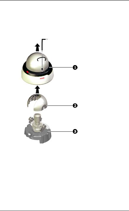
The camera/housing unit consists of the following parts:
x2
1.Dome
2.Inner liner
3.Camera module and mounting base
To disassemble the unit proceed as follows:
1.Using the special screwdriver bit supplied, loosen the two tamper-resistant screws in the dome (the screws remain in place).
2.Remove the dome from the base.
3.Remove the inner liner by pulling it off the base.
Bosch Security Systems |
Installation and Operation Manual |
AR18-10-B012 | v1.5 | 2011.01 |
16 en | Installation |
IP Camera 200 Series |
|
|
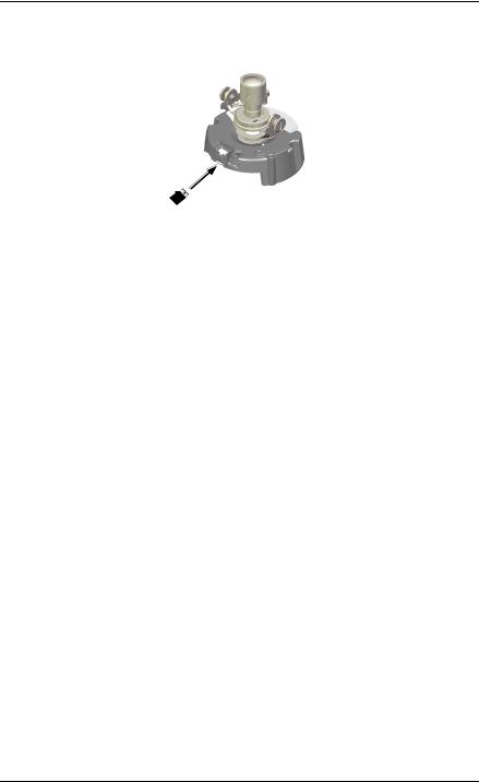
3.2MicroSDHC card
microSDHC Card
Figure 3.1 MicroSDHC card
1.Disassemble the camera.
2.Slide the microSDHC card into the slot.
The camera supports most microSD/SDHC cards.
AR18-10-B012 | v1.5 | 2011.01 |
Installation and Operation Manual |
Bosch Security Systems |
IP Camera 200 Series |
Installation | en 17 |
|
|
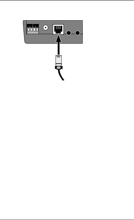
3.3Network (and power) connector
1 2 3 4 |
DC 12V |
Ethernet |
Line-out |
Line-in |
RJ45
Ethernet (PoE)
Figure 3.2 Network connection
–Connect the camera to a 10/100 Base-T network.
–Use a shielded UTP Category 5e cable with RJ45 connectors.
–Power can be supplied to the camera via the Ethernet cable compliant with the Power-over-Ethernet
(IEEE 802.3af) standard.
Bosch Security Systems |
Installation and Operation Manual |
AR18-10-B012 | v1.5 | 2011.01 |
18 en | Installation |
IP Camera 200 Series |
|
|
3.4Power connection
The camera can accept power from both the DC12V power input and the Ethernet input at the same time. You can remove either one of the power sources without interrupting camera operation.
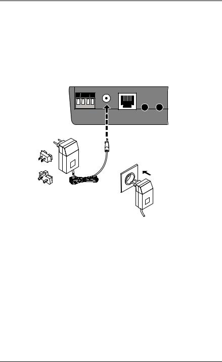
3.4.1DC power connection
1 2 3 4 |
DC 12V |
Ethernet |
Line-out |
Line-in |
Figure 3.3 DC power connection
1.Slide the plug adapter that matches your outlet socket onto the supplied power supply.
2.Insert the power connector jack from the power supply into the DC12V socket of the camera.
3.Connect the power supply to either a 230 VAC or a
120 VAC power supply outlet.
When power is supplied to the camera the LED on the bottomfront of the camera lights. (This LED can be disabled in the Installer menu.)
AR18-10-B012 | v1.5 | 2011.01 |
Installation and Operation Manual |
Bosch Security Systems |
IP Camera 200 Series |
Installation | en 19 |
|
|
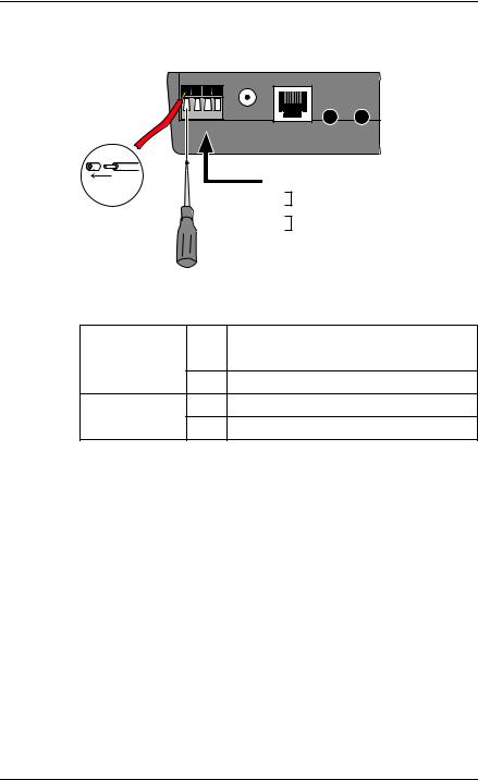
3.5I/O connector
1 2 3 4 |
DC 12V |
Ethernet |
Line-out |
Line-in |
5 mm |
Pin I/O |
|
(0.2 in) |
1 |
Relay out |
|
2 |
|
|
|
|
|
3 |
Relay in |
|
4 |
|
|
|
|
Figure 3.4 I/O connector pins
Function |
Pin |
I/O socket |
|
|
|
Relay |
1 |
Relay out |
2Relay out
Alarm input |
3 |
Relay in |
4Relay in
–Max. wire diameter AWG 22-28 for both stranded and solid; cut back 5 mm (0.2 in) of insulation.
–Relay output switching capability: Max. voltage 24 VAC or 24 VDC. Max. 1 A continuous, 12 VA.
–Relay in: Short or +5 VDC activation.
–Alarm input configurable as active low or active high.
Bosch Security Systems |
Installation and Operation Manual |
AR18-10-B012 | v1.5 | 2011.01 |
20 en | Installation |
IP Camera 200 Series |
|
|
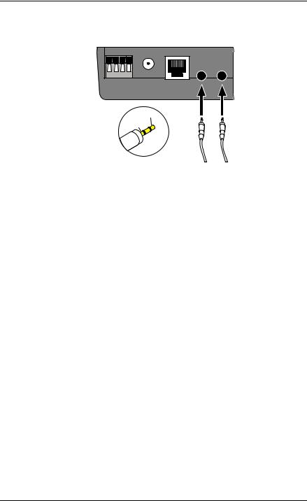
3.6Audio connectors
1 2 3 4 |
DC 12V |
Ethernet |
Line-out |
Line-in |
Line in: 9 kOhm typ., |
Line - L |
|
|
200 mVrms |
GND |
Line out: 16 Ohm min.  200 mVrms (earphone Line - R compatible)
Figure 3.5 Audio connectors
Connect audio devices to the Line In and Line Out connectors.
AR18-10-B012 | v1.5 | 2011.01 |
Installation and Operation Manual |
Bosch Security Systems |
IP Camera 200 Series |
Installation | en 21 |
|
|
3.7Mounting
x2
6mm  Ø
Ø 
M4 (Ø3.3 mm)
x2
Figure 3.6 Mounting the camera
To mount the camera to a wall or ceiling:
1.Stick the supplied installation paper sticker to the surface taking care to orientate it correctly.
2.Drill two holes with a diameter of 6 mm.
3.Insert the supplied plugs into the holes.
4.Attach the camera and base unit securly to the surface using the two supplied M4 screws.
CAUTION!
Do not point the camera/lens into direct sunlight as this may damage the sensors.
Bosch Security Systems |
Installation and Operation Manual |
AR18-10-B012 | v1.5 | 2011.01 |
22 en | Installation |
IP Camera 200 Series |
|
|
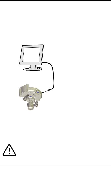
3.8Camera set-up
To help set up the camera, connect a monitor to the miniature 2.5 mm jack socket using a S1460 monitor cable which can be ordered separately. This monitor jack socket provides a composite video signal (with sync) for installation purposes only.
S1460
3.8.1Camera positioning
The camera module position can be adjusted along three axes. When adjusting the camera position ensure that the picture display on the monitor is level.
CAUTION!
The image sensors are highly sensitive and require special care for proper performance and extended lifetime. Do not expose them to direct sunlight or bright spotlights in operating and non-operating conditions. Avoid bright lights in the field of view of the camera.
AR18-10-B012 | v1.5 | 2011.01 |
Installation and Operation Manual |
Bosch Security Systems |
IP Camera 200 Series |
|
Installation | en 23 |
|
|
|
|
|
|
|
|
|
|
|
|
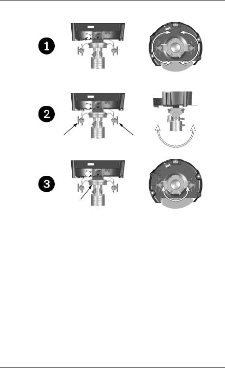
Set the camera to the desired position by performing the following steps:
1.For horizontal adjustment (pan), rotate the camera module in the base. Do not rotate more than 350°.
2.For vertical adjustment (tilt), loosen thumbscrews, position camera, then gently tighten thumbscrews to secure camera.
3.To obtain a horizontal horizon (for tilted ceilings or sidewall mounting), rotate the base of the lens as necessary to align the picture shown on the monitor. Do not rotate more than 340°.
Bosch Security Systems |
Installation and Operation Manual |
AR18-10-B012 | v1.5 | 2011.01 |
24 en | Installation |
IP Camera 200 Series |
|
|
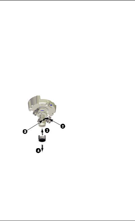
3.8.2Focal length and focus
Adjust the focal length and focus as follows:
1.Slide the focus aid onto the lens.
2.To set the field of view of the varifocal lens, loosen the focal length screw and turn the mechanism until the required view is displayed on the monitor (Image goes out of focus.)
3.Focus the image on the monitor by loosening the focus screw and turning the mechanism until the image is in focus.
4.Readjust the focal length if necessary.
5.Repeat these two adjustments until the desired view is in focus.
6.Tighten both screws.
7.Remove the focus aid from the lens.
1.Attach focus aid
2.Set focal length
3.Adjust focus
4.Remove focus aid
AR18-10-B012 | v1.5 | 2011.01 |
Installation and Operation Manual |
Bosch Security Systems |
IP Camera 200 Series |
Installation | en 25 |
|
|
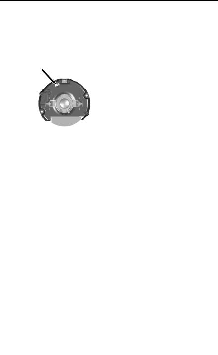
3.9Resetting the camera
If the camera cannot be connected because the IP address has changed, press and hold the reset button (7 seconds approximately) until the LED flashes (red) to recall the factory default values. The factory default IP address is 192.168.0.1
Figure 3.7 Reset button
3.10Closing the unit
When the camera position is set and all adjustments have been made, close the unit.
1.Remove the monitor cable from the jack socket. (Ensure focus aid has been removed.)
2.Click the inner liner in position aligning the opening with the lens.
3.If necessary clean its surface with a soft cloth.
4.Align the LED light guide of the dome with the opening at the front of the mounting base and slot it home.
5.Use the supplied special screwdriver bit to tighten the two tamper-resistant screws.
Bosch Security Systems |
Installation and Operation Manual |
AR18-10-B012 | v1.5 | 2011.01 |

26 en | Installation |
IP Camera 200 Series |
|
|
AR18-10-B012 | v1.5 | 2011.01 |
Installation and Operation Manual |
Bosch Security Systems |

IP Camera 200 Series |
Browser connection | en 27 |
|
|
4Browser connection
A computer with Microsoft Internet Explorer can be used to receive live images from the camera, control cameras, and replay stored sequences. The camera is configured over the network using a browser or via the Bosch Video Client (supplied with the product).
4.1System requirements
–Microsoft Internet Explorer version 7.0 or higher
–Monitor: resolution at least 1024 × 768 pixels, 16 or 32 bit color depth
–Intranet or Internet network access
The Web browser must be configured to enable Cookies to be set from the IP address of the unit.
In Windows Vista, deactivate protected mode on the Security tab under Internet Options.
To play back live video images, an appropriate ActiveX must be installed on the computer. If necessary, the required software and controls can be installed from the product CD provided.
a.Insert the CD into the CD-ROM drive of the computer. If the CD does not start automatically, open the root directory of the CD in Windows Explorer and double click BVC-installer.exe
b.Follow the on-screen instructions.
4.2Establishing the connection
The camera must be assigned a valid IP address to operate on your network. The default address pre-set at the factory is
192.168.0.1
1.Start the Web browser.
2.Enter the IP address of the camera as the URL.
Bosch Security Systems |
Installation and Operation Manual |
AR18-10-B012 | v1.5 | 2011.01 |

28 en | Browser connection |
IP Camera 200 Series |
|
|
Note:
If the connection is not established, the maximum number of possible connections may already have been reached. Depending on the device and network configuration, up to 25 web browsers, or 50 Bosch VMS connections are supported.
4.2.1Password protection in camera
A camera offers the option of limiting access across various authorization levels. If the camera is password-protected, a message to enter the password appears.
1.Enter the user name and the associated password in the appropriate fields.
2.Click OK. If the password is correct, the desired page is displayed.
4.3Protected network
If a RADIUS server is used for network access control (802.1x authentication), the camera must be configured first. To configure the camera for a Radius network, connect it directly to a PC via a crossed network cable and configure the two parameters, Identity and Password. Only after these have been configured can communication with the camera via the network occur.
AR18-10-B012 | v1.5 | 2011.01 |
Installation and Operation Manual |
Bosch Security Systems |

IP Camera 200 Series |
Browser connection | en 29 |
|
|
4.4Connection established
When a connection is established, the LIVEPAGE is initially displayed. The application title bar displays the type number of the connected camera and three items: LIVEPAGE,
RECORDINGS, SETTINGS.
Note:
The RECORDINGS link is only visible if a storage medium is available.
Figure 4.1 Livepage
4.4.1LIVEPAGE
The LIVEPAGE is used to display and control the video stream. Refer to Section 7.1 Livepage, page 93 for more information.
4.4.2RECORDINGS
Click RECORDINGS in the application title bar to open the playback page. Refer to Section 7.2 Recordings page, page 98 for more information.
4.4.3SETTINGS
Click SETTINGS in the application title bar to configure the camera and the application interface. A new page containing
Bosch Security Systems |
Installation and Operation Manual |
AR18-10-B012 | v1.5 | 2011.01 |

30 en | Browser connection |
IP Camera 200 Series |
|
|
the configuration menu is opened. All settings (except date/ time) are stored in the camera memory so that they are retained, even if the power is interrupted.
Changes that influence the fundamental functioning of the unit (for example, firmware updates) can only be made using the configuration menu.
The configuration menu tree allows all parameters of the unit to be configured. The configuration menu is divided into Basic Mode and Advanced Mode.
Refer to Section 5 Basic Mode, page 31 for more information on basic settings; refer to Section 6 Advanced Mode, page 37 for more information on advanced settings.
Note:
It is recommended that only expert users or system administrators use the Advanced Mode.
AR18-10-B012 | v1.5 | 2011.01 |
Installation and Operation Manual |
Bosch Security Systems |
Loading...