


MIC412 Dual Optical / Thermal
PTZ Camera
Bosch Security Systems
EN Installation and Operation Manual

MIC412TI and MIC412TF Camera | Installation and Operation Manual |
EN | 2 |
MIC 412 Dual Optical / Thermal PTZ Camera
Installation and Operation Manual
For the MIC412TI and MIC412TF PTZ camera models
Chapters
1. Introduction
2. Hardware Installation
3. Power Supply Installation
4. Configuring the MIC412 Camera
5. Technical Specifications
Bosch Security Systems |
Issue 8 |

MIC412TI and MIC412TF Camera | Installation and Operation Manual
Introduction.............................................................. |
1-6 |
MIC412 PTZ Camera........................................................................... |
1-6 |
MIC412 Versions and Options............................................................. |
1-7 |
MIC412 Power Supply Option Versions and Options.......................... |
1-7 |
Features............................................................................................... |
1-8 |
Unpacking............................................................................................ |
1-8 |
Package Contents................................................................................ |
1-8 |
Installation Environment....................................................................... |
1-9 |
Associated Equipment and typical installations.................................... |
1-11 |
Hardware Installation............................................... |
2-12 |
Installation Instructions......................................................................... |
2-12 |
Earthing Instructions............................................................................. |
2-13 |
Lightning Protection.............................................................................. |
2-13 |
Electrical Connections.......................................................................... |
2-13 |
Power Supply Installation and Camera Setup…...... 3-14
MIC-240THERMALPSU and MIC-115THERMALPSU….…..………… 3-14
PCB Earth Link……….......................................................................... |
3-15 |
Power Supply layout and connections................................................. |
3-15 |
Fuse Ratings………………………………………….............................. |
3-16 |
Installation Instructions……………………………………………………. 3-16 |
|
Commissioning the MIC412 Heater option................…..….………….. 3.17 |
|
Fitting the optional Sunshield....................……………………………... 3-18 |
|
Configuring the MIC412 Camera............................. |
4-19 |
Connecting the MIC412 to a PC......................................................... |
4-19 |
Connecting the Greenwich Adaptor.................................................... |
4-19 |
Connecting the K2 ADE Adaptor........................................................ |
4-19 |
Connecting the MIC-USB485Converter.............................................. |
4-20 |
MIC-USB495CVTR and Universal Camset Software Installation……. |
4-21 |
Commissioning the MIC412 via Universal Camset............................. |
4-22 |
Standard Controls............................................................................... |
4-22 |
MIC Setups......................................................................................... |
4-27 |
Privacy and Captions.......................................................................... |
4-32 |
Thermal............................................................................................... |
4-35 |
Advanced Settings.............................................................................. |
4-36 |
POT Test............................................................................................. |
4-38 |
EN | 3 |
|
Comms................................................................................................ |
4-40 |
Sonyset............................................................................................... |
4-42 |
MIC Programmer................................................................................. |
4-45 |
Help..................................................................................................... |
4-47 |
MIC412 Preset Codes for the Thermal Imager………………………… 4-48 |
|
Technical Specifications......................................... |
5-49 |
Technical Specifications…………………………….…………………… |
5-49 |
Dimension Drawings……………………………………………………... |
5-51 |
Appendix A......................................................................................... |
5-51 |
Appendix B………………………………………………………………… 5-52
Bosch Security Systems |
Issue 8 |

MIC412TI and MIC412TF Camera | Installation and Operation Manual
Safety Precautions
The following symbols are used throughout this manual please pay careful attention to their meaning.
The lightning flash with an arrowhead symbol within a triangle is intended to alert the user to the presence of non-insulated “dangerous voltage” within the product’s enclosure that may be of sufficient magnitude to constitute a risk of electric shock to persons.
The exclamation point within a triangle is intended to alert the user to the presence of important safety, operating and maintenance (servicing) instructions in the literature accompanying the appliance.
Important Safety Instructions
CAUTION
TO REDUCE THE RISK OF ELECTRICAL SHOCK,
DISCONNECT POWER SUPPLY BEFORE OPENING THE
POWER SUPPLY UNIT.
POWER DISCONNECT: POWER SUPPLY UNITS HAVE
POWER SUPPLIED WHENEVER THE POWER CORD IS
INSERTED INTO THE POWER SOURCE.
WARNING
INSTALLATION SHOULD BE CARRIED OUT BY QUALIFIED
PERSONNEL IN ACCORDANCE WITH THE NATIONAL
ELECTRIC CODE, ANSI/NFPA, CANADIAN ELECTRICAL
CODE, AND ALL LOCAL COUNTRY CODES.
BOSCH SECURITY SYSTEMS ACCEPTS NO LIABILITY
FOR ANY DAMAGES OR LOSSES CAUSED DUE TO
INCORRECT OR IMPROPER INSTALLATION.
EN | 4
WARNING
INSTALL EXTERNAL INTERCONNECTING CABLES IN ACCORDANCE TO NEC, ANSI/NFPA70 (FOR US APPLICATION) AND CANADIAN ELECTRICAL CODE, PART I, CSA C22.1 (FOR CAN APPLICATION) AND IN ACCORDANCE TO LOCAL COUNTRY CODES FOR ALL OTHER COUNTRIES.
BRANCH CIRCUIT PROTECTION INCORPORATING A 20 A, 2-POLE LISTED CIRCUIT BREAKER OR BRANCH RATED FUSES ARE REQUIRED AS PART OF THE BUILDING INSTALLATION.
A READILY ACCESSIBLE 2-POLE DISCONNECT DEVICE WITH A CONTACT SEPARATION OF AT LEAST 3 mm MUST BE INCORPORATED.
ROUTING OF EXTERNAL WIRING MUST BE DONE THROUGH A PERMANENTLY EARTHED METAL CONDUIT.
WARNING
THE CAMERA MUST BE MOUNTED DIRECTLY AND PERMANENTLY TO A NON-COMBUSTIBLE SURFACE.
Bosch Security Systems |
Issue 8 |

MIC412TI and MIC412TF Camera | Installation and Operation Manual |
EN | 5 |
IMPORTANT SAFETY INSTRUCTIONS
1.Read these instructions
2.Keep these instructions
3.Heed all warnings
4.Follow all instructions
5.Install according to manufacturer’s instructions
6.Do not install near any strong heat sources such as furnaces
7.Do not open the camera unit, doing so invalidates the unit’s warranty
8.Do not back-drive the pan or tilt axis of the camera. To do so will damage the motor drive gear chain and will invalidate the warranty
9.Do not use caustic or abrasive cleaning products on the unit
10.Do not point the MIC412 camera at the sun. Bosch Security Systems Ltd will not be liable for any damages to cameras which have been directly pointed at the sun
11.In situations where there could be a risk of injury should any part of the assembly become detached for any reason and fall, normal common sense safety precautions should be employed; a strong safety chain between the camera pan shaft and the mounting surface is recommended
12.For transportation please rotate the ball so the window points towards the base, this helps to protect the wiper & windows during transit
13.Ensure that the product case is properly earthed. If the product is likely to be struck by lightning, ensure that earth-bonding connections are made correctly to the mounting base of the unit
14.Use only the power sources indicated in this user guide and ensure that the current rating of the supply cable is adequate for the product
15.Do not stand canted (45°) MIC412’s upright as they can be easily knocked over, lay them on their side.
Bosch Security Systems |
Issue 8 |

MIC412TI and MIC412TF Camera | Installation and Operation Manual
This product complies with the following EC directives:-
EMC Directive (89/336/EC as amended)
Machinery Directive (98/37/EC)
LV Directive (73/23/EC)
RoHS (Restriction of Hazardous Substances) 2002/95/EC
WEEE (Waste Electrical & Electronic Equipment) 2002/96/EC
This equipment contains electrical or electronic components that must be recycled properly to comply with Directive 2002/96/EC of the European Union regarding the disposal of waste electrical and electronic equipment (WEEE). Contact your local supplier for procedures for recycling this equipment.
EN | 6
|
|
Reference |
Glossary of Terms |
|
|
PTZ |
- |
Pan/Tilt/Zoom |
Bi-phase |
- |
Bosch Bi-phase telemetry protocol (see pg8) |
PSU |
- |
Power Supply Unit |
IR |
- |
Infra Red |
BP3 or 4 |
- |
Bi-phase converter cards for MIC400 range of cameras |
STP |
- |
Shielded Twisted Pair cable |
Glossary of Appendices |
||
Appendix A |
- |
Sonyset Camera Commands |
Appendix B |
- |
Protocol Preset Codes |
Bosch Security Systems |
Issue 8 |

MIC412TI and MIC412TF Camera | Installation and Operation Manual |
|
EN | 7 |
CHAPTER 1 |
Introduction |
|
The MIC412 Dual Optical/Thermal PTZ camera is a high specification, weatherproof, ruggedized, fully functional pan tilt zoom CCTV camera system incorporating a Sony optical camera module paired with a Flir Photon thermal imager. This combination allows for the covert detection of human sized targets at ranges up to 780M in complete darkness or to lesser ranges in adverse weather conditions.
The MIC412 has been designed to offer an extremely reliable, robust and high quality surveillance solution for security applications that demand the very best performance. Precision engineered to exacting standards, the range offers numerous benefits over the use of traditional dome and PTZ cameras and comes with a variety of options in order to offer a best fit solution for virtually any application.
Rated to an industry leading IP67, the compact vandal resistant 6mm thick aluminium camera housing is suitable for installation in the harshest of environments, while the optically perfect flat viewing window and integrated wiper option ensure razor sharp images are captured in even the most demanding conditions.
Brushless motor technology ensures ultra-reliable, whisper quiet operation while groundbreaking resolver technology provides pin-point accuracy and affords the user full 360° continuous rotation pan and an unprecedented 320° tilt control.
A choice of true day/night camera modules, offering up to 36x optical zoom (12x digital), along with a choice of 9hz or 25hz* thermal imagers coupled with flexible upright or inverted mounting capability, allows the perfect field of view to be achieved every time even in poor conditions.
Bosch Security Systems |
Issue 8 |

MIC412TI and MIC412TF Camera | Installation and Operation Manual
MIC412 Camera Versions
This manual covers the installation & operation of the following MIC 412TI and MIC 412TF Dual optical thermal PTZ cameras, briefly described below:-
MIC 412TI The MIC 412TI is made from machined and cast aluminium and is then pre-treated and painted with two part epoxy power coat paint in either RAL 9003 (Signal White)or RAL9005 (Jet Black), other colours are available on request.. This unit incorporates a choice of 18x or 36x Day/Night optical camera paired with a 50mm 9Hz Flir Thermal Imager.
MIC41 2TF The MIC 412TF camera is made to the same specification as the MIC412TI but fitted with a 25Hz Flir Thermal Imager, the 18x and 36x Day/Night optical camera choices remain.
EN | 8
MIC 412 Power Supply Unit Versions and Options
CAUTION: Only use the specified power supplies with the
MIC 412.
Bosch Security Systems have designed a range of power supplies for the MIC412 cameras to cater for a variety of common voltages and provide all the connections needed for power, telemetry and video. The power supply units and options are detailed below. Refer to the MIC Series Power Supplies Installation Manual.
For MIC412 cameras only:- |
|
MIC-240PSU-UL |
240VAC input Power Supply Unit |
MIC-115PSU-UL |
115VAC input Power Supply Unit |
MIC-24PSU-UL |
24 VAC input Power Supply Unit |
DANGER:. ELECTRICAL SHOCK HAZARD
Ensure the power is disconnected prior to opening the power supply enclosure. Power must be disconnected before replacing any fuse in the MIC PSU.
The MIC power supplies have a separate internal shield covering the power cable input header (HD1).
Only suitably qualified persons should remove this shield and connect the mains power cable, the shield MUST be refitted and fully secured prior to connecting the power.
The mains supply cable shall have conductors of a maximum size of 12 AWG. A readily accessible disconnect device (circuit breaker) shall be incorporated externally to the equipment. The recommended rating is 15 A.
Bosch Security Systems |
Issue 8 |

MIC412TI and MIC412TF Camera | Installation and Operation Manual
MIC 412 Options
Options include the following:-
Wiper |
a rubber wiper blade mounted on a spring loaded arm is available |
|
as standard on all MIC412 versions. |
Heater Two (2) 10w heaters can be fitted to MIC412 versions giving improved low temperature performance down to -30°C.
Sunshield A two (2) part plastic sunshield to provide additional protection in sunny climates.
MIC-WKT Washer bracket, nozzle and washer pump drive card kit.
MIC-ALM 8-input alarm card includes washer pump drive function.
MIC-BP3 Bosch Bi-phase converter card for power supplies without expansion slots available.
MIC-BP4 Bosch Bi-phase converter card for power supplies with an expansion slot available.
Features
The MIC412 series cameras have the following features:
•Brushless Motor Technology for whisper quiet operation.
•Large protocol selection available for easy integration
•Canting option to allow bottom of pole vision
•Choice of 18x or 36x camera modules
•Wide range of mounting options for varied applications
•Optically flat viewing window
EN | 9
Unpacking
CAUTION: Ensure canted (45°) MIC412’s are laid on their side; do not stand upright as they are unstable.
CAUTION: Take extra care lifting or moving MIC412 units due to their weight.
•Check the exterior of the packaging for visible damage. If any items appear to have been damaged in transit please inform the shipping company.
•Unpack the power supply unit carefully; although ruggedized this is electronic equipment & should be handled with care.
•Do not use if any component appears to be damaged. Please contact Bosch Security Systems Ltd in the event of damaged goods.
•The shipping cartoon is the best way to transport the unit, save it & all other packaging materials for future use. If the unit must be returned, use the original packing materials.
Packaging Contents
Please check for the following contents
•MIC412 Installation & Operation manual (this guide)
•Installation & Configuration CD
•Quick start reference sheet
•Nebar Gasket
•MIC412 Dual Optical/Thermal PTZ Camera
Bosch Security Systems |
Issue 8 |

MIC412TI and MIC412TF Camera | Installation and Operation Manual |
EN | 10 |
Installation Environment
CAUTION: Ensure that the National Electric Code, ANSI/NFPA, Canadian Electric Code, and all local country codes are observed when installing this product. Ensure a strong safety chain is used to secure the MIC412 camera to prevent any danger of dropping the product during installation. Particular care should be taken with MIC412 models due to the additional weight.
The MIC412 has been designed to be easily installed on a variety of common fittings. Most commonly a dedicated CCTV camera pole is used, the MIC412 will bolt directly to the top of most poles using the industry standard 4 in. (101.6 mm) fitting. Such camera poles provide robust mounting platforms that minimize camera motion and typically have large base cabinets to mount all ancillary equipment such as power supplies.
The MIC412 cameras can also be mounted on lamp post columns using the Pole Mount Bracket (MIC-PMB) however users should be aware that lamp posts can often be subject to movement and are not suitable platforms in all conditions or for all applications.
For mounting directly onto buildings Bosch Security Systems manufactures a range of brackets suitable for all typical building installations for upright (90°), canted (45°) or Inverted camera positions.
Bosch Security Systems |
Issue 8 |
MIC412TI and MIC412TF Camera | Installation and Operation Manual |
EN | 11 |
Bosch Security Systems |
Issue 8 |
MIC412TI and MIC412TF Camera | Installation and Operation Manual |
EN | 12 |
Associated Equipment and Typical Installations
The robust nature of the MIC412 range of cameras make it ideal for installation in all typical domestic and commercial CCTV applications such as residential homes, shopping centres, commercial premises, military/ government installations, ports & airports to name but a few.
The MIC412’s adaptability enables easy integration in a wide variety of mobile and re-deployable installations these have included Lifeboats and other surface/subsurface vessels, Emergency service vehicles, Highways Agency vehicles, Council/Contractor parking enforcement vehicles and Crowd control vehicles.
The MIC412 uses a composite cable to carry all power and telemetry between the camera head and the MIC power supply unit this cable can be a maximum of 25 m long, for installations which require the camera head to be more than 25 m from the power supply then it is recommended that a 2m cable be connected to a junction box from which telemetry; video and power can be broken out into separate cables and appropriate wiring used to extend the distance to suit.
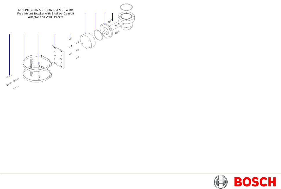
Key to MIC-PMB drawing
1.Securing bolts for MIC-SCA
2.90mm stainless steel pole banding
3.Pole mount bracket blocks
4.Pole mount bracket plate
5.Pole mount block securing bolts
6.Shallow conduit adaptor
7.“O”-ring
8.Wall mount bracket
9.Wall mount bracket securing bolts
Bosch Security Systems |
Issue 8 |

MIC412TI and MIC412TF Camera | Installation and Operation Manual
CHAPTER 2 Hardware Installation
CAUTION: Ensure that the National Electric Code, ANSI/NFPA, Canadian Electric Code, and all local country codes are observed when installing this product. Ensure a strong safety chain is used to secure the MIC 412 camera to prevent any danger of dropping the product during installation. Particular care should be taken with MIC 412 models due to the additional weight.
CAUTION: Fasteners are not supplied with the camera since it depends on the material to which it is attached. The material must accommodate a minimum pull out strength of 275 kg (600 lbs.) Fasteners can include wedge anchors, sleeve anchors, single expansion anchors, double expansion anchors, machine screw anchors, or Thru Bolting with a nut. All fasteners must be made of 303(A2) stainless steel, at a minimum, with a diameter of 9 mm (5/16-in).
All bolts must fully extend through the mounting surface and be secured with a flat washer, lock washer and a nut. All studs must be anchored to concrete or welded to a steel backing plate. Anchor bolts can be used for blind structures where there is no access to the rear.
Installation Instructions
1.Locate the mounting position of the camera so that it cannot be interfered with either intentionally or accidentally.
2.Ensure the mounting surface is capable of supporting the combined weight of the camera and mounting hardware under all expected conditions of load, vibration and temperature.
The MIC 412 must be secured to one of the following surfaces:
•Concrete Solid/Cast
•Concrete Masonry Unit (Concrete Block)
•Brick (all type)
•Metal (Steel/Aluminum, minimum 1/8-in. thick)
EN | 13
3.Fit the mounting brackets securely, observing all appropriate safety precautions and local building regulations.
4.Ensure that the mating 12-pin connector is fitted properly in the camera plug. Confirm that the 25 mm connector sleeve on the top of the composite cable is done up tightly (approx. four turns from start of thread engagement).
5.Earth the camera using one of the securing bolts. Only earth the camera at a single point to prevent earth loops and hum bars.
6.M8 x 20mm Stainless steel nuts, bolts and washers should be used to secure the 4 in. PCD camera base to the mounting bracket. An additional Nebar gasket or suitable silicone sealant can be used to ensure a water tight seal between the 4 in. PCD base and mounting surface. Ensure all bolts are securely tightened. Secure all cabling and conduit.
CAUTION: If the camera is mounted ball down it is essential that the connector and base area of the camera are completely sealed from water ingress.
CAUTION: Any water getting into the connector is liable to cause corrosion to the connector pins leading to unreliable operation of the camera unit.
CAUTION: To prevent water penetrating the composite cable connector threads, the 25 mm thread should be sealed at final installation using PTFE tape. Alternatively a suitable sealant may be liberally applied to the thread prior to final tightening.
Refer to the MIC Series Bracketry Installation Guide for more information about each MIC mounting option.
Bosch Security Systems |
Issue 8 |

MIC412TI and MIC412TF Camera | Installation and Operation Manual
Earthing of the MIC 412 camera
1.The camera module and housing are electrically isolated so the housing should be safety earthed regardless. The safety earth should be a bonding connection to the cameras outside case for example one of the securing bolts.
2.The camera should be earthed at one point only to prevent earth loops & thus hum bars showing on the control room monitor.
3.If the system is copper throughout & the camera pictures are fed back to the control room coaxial copper cable, then the camera should be earthed at the video termination point in the control room & nowhere else. In this case the PCB “Earth Link” should be broken.
4.If the video is transmitted back to the control room via some non electrical connecting medium, e.g. fibre optic, radio or microwave link, then the camera should be earthed at the transmitter point in the PSU. The PSU “Earth Link” may be used for this purpose.
5.If dual earthing is unavoidable then a video isolation transformer should be fitted between the two earths.
Lightning Protection
If the camera is fitted in a highly exposed place then consideration should be given to lightning protection. A good earth bonding connection to the case itself will provide protection against damage from secondary strikes.
Where there is a risk of a primary strike hitting the camera housing directly, it is recommended that a separate lightning conductor be fitted within 0.5m of the camera and at least 1.5 m higher than the camera.
The construction of the housing itself is very capable of coping with secondary strikes and no damage to the internal electronics or camera should result if correct lightning protection is applied.
EN | 14
Electrical Connections
WARNING: Electrical Danger: Ensure all power is disconnected before opening or working upon the Power Supply Unit.
Installation must be carried out by suitably qualified persons. Ensure that the National Electric Code, ANSI/NFPA, Canadian Electric Code, and all local country codes are observed.
A purpose built composite cable for use with the camera is available; these cables are pre-made with a Female terminated 12 way connector fitted to them for attachment to the Male connector installed into the base of the camera.
The composite cable has no termination (free wires) at the other end for wiring into the appropriate power supply. The standard colour coding used in these cables is as shown below.
Table A – MIC412 Composite Cable Pin table
|
|
|
|
|
|
|
|
Connector Pin |
|
Signal Name |
|
Wire Colour |
|
|
|
|
|
|
|
|
|
A |
|
Video Output |
|
Coax core |
|
|
|
|
|
|
|
|
|
B |
|
Video Return |
|
Coax screen |
|
|
|
|
|
|
|
|
|
C |
|
Tamper Sw |
|
Black |
|
|
|
|
|
|
|
|
|
D |
|
Tamper Sw Rtn |
|
Brown |
|
|
|
|
|
|
|
|
|
E |
|
Washer drive Rtn |
|
Grey |
|
|
|
|
|
|
|
|
|
F |
|
Washer drive |
|
Orange |
|
|
|
|
|
|
|
|
|
G |
|
Full Duplex Tx A. |
|
Blue |
|
|
|
|
|
|
|
|
|
H |
|
Full Duplex Tx B. |
|
Violet |
|
|
|
|
|
|
|
|
|
I |
|
Full Duplex Rx A. |
|
Yellow |
|
|
|
|
Half Duplex Tx/Rx A. |
|
|
|
|
|
|
|
|
|
|
|
K |
|
Full Duplex Rx B. |
|
White |
|
|
|
|
Half Duplex Tx/Rx B. |
|
|
|
|
|
|
|
|
|
|
|
L |
|
Power input 1. |
|
Red |
|
|
|
|
|
|
|
|
|
M |
|
Power input 2. |
|
Green |
|
|
|
|
|
|
|
|
Bosch Security Systems |
Issue 8 |

MIC412TI and MIC412TF Camera | Installation and Operation Manual
CHAPTER 3 Power Supply Installation
Note: Refer to the MIC Series Power Supplies Installaion Manual for detailed power supply information.
MIC 412TI and MIC 412TF Power Supply Units
MIC-24PSU-UL, MIC-115PSU-UL, and MIC-240PSU-UL
The power supply provides power for a single MIC412 camera unit from either a 24 VAC source (MIC-24PSU-UL), 240 VAC source (MIC-240PSU-UL) or a 115 VAC source (MIC-115PSU-UL).
In addition the unit provides all the terminations required to connect a MIC 412 camera to third party equipment.
A second independent 12 V (600 mA) power supply is also included to drive any internally fitted optional interface cards.
Dimensions (W x H x L):
Power supply enclosure: 240 x 90.5 x 160 mm (9.5 x 3.6 x 6.3 in.)
WARNING: All external wires for installation applications must be routed through a permanently earthed metal conduit.
The Power Supply Unit provides all the support functions for connecting the camera to third party equipment. It comprises of:
EN | 15
1.A weather-resistant (IP65) cast-aluminium box pre-fitted with three (3) cable glands.
2.A power supply for the MIC 412 camera.
3.Provision for driving various interface cards mounted internally to the power supply box, for example an alarm interface card (non-IR power supplies only).
4.Provision for a signal interface card (BP-3 or BP-4) to connect telemetry to Bosch Biphase equipment.
5.Screw termination of all composite, telemetry and ancillary cables in the box.
6.Earth isolation and termination within the unit to correctly control video earthing and to prevent earth loop.
PCB Earth Link
The PCB has one link option next to HD1 to allow the power supply to be set up for different earthing schemes: The Earth Link should be broken if there is a separate connection between video screen and earth. This usually occurs on copper connected systems where all the copper video coaxes are taken back to the control room to be connected to a central earth point. If fibre optics or other indirect connections are used to get data and video to and from the control room then the earth link should be left intact provided it is the only camera end earth reference point.
Power Supply Layout and Connections
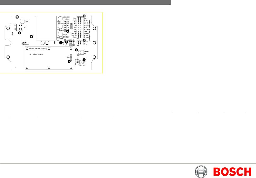
The power supply PCB has the following connections as shown on Figure A:-
HD1 – Power Input Connector (screw terminal) HD2 - Tamper Switch header (screw terminal)
HD3 - Composite cable header (Connections to camera head, screw terminal) HD4 - Telemetry header (molex connection)
HD5 - Telemetry header (screw terminal) HD6 - Washer pump header (screw terminal)
HD8 - Keyboard power connector (demo purposes only, not normally fitted) CN1 - Video out connection header (BNC)
CN2 - Add on card header (plug in)
Figure A and the following tables show the connections required.
Bosch Security Systems |
Issue 8 |
MIC412TI and MIC412TF Camera | Installation and Operation Manual
Figure A - MIC-Non-IR Power Supply Layout
Table B – Power Connections
|
|
|
|
|
|
|
|
|
|
Item |
|
PSU Terminal |
|
Description |
|
Connection |
|
|
|
|
|
|
|
|
|
|
|
|
|
|
|
|
|
|
|
|
1 |
|
HD1 |
|
Power cable terminal |
|
Screw terminal |
|
|
|
|
|
|
|
|
|
|
|
2 |
|
HD2 |
|
Tamper switch terminal |
|
Screw terminal |
|
|
|
|
|
|
|
|
|
|
|
3 |
|
HD3 |
|
Composite cable terminal |
|
Screw terminal |
|
|
|
|
|
|
|
|
|
|
|
4 |
|
HD4 and HD5 |
|
Telemetry terminal |
|
Screw terminal or |
|
|
|
|
|
|
|
|
Molex crimp |
|
|
|
|
|
|
|
|
|
|
|
5 |
|
HD6 |
|
Heater terminal |
|
Screw terminal |
|
|
|
|
|
|
|
|
|
|
|
6 |
|
HD8 |
|
Optional MC-516 kbd |
|
Molex crimp |
|
|
|
|
|
|
power terminal |
|
|
|
|
|
|
|
|
|
|
|
|
|
7 |
|
CN1 |
|
Coax video terminal |
|
BNC socket |
|
|
|
|
|
|
|
|
|
|
|
8 |
|
CN2/3 |
|
Auxiliary card terminal |
|
Plug in |
|
|
|
|
|
|
|
|
|
|
EN | 16
Table C - Composite cable to Power Supply HD-3 Connection Table
|
|
|
|
|
|
|
|
|
|
Composite |
|
Function |
|
Terminal Box |
|
Terminal |
|
|
Cable Wire |
|
|
|
Connector |
|
Box ID |
|
|
Color |
|
|
|
|
|
Marking |
|
|
|
|
|
|
|
|
|
|
|
Red |
|
AC supply |
|
HD3-1 |
|
Power |
|
|
|
|
|
|
|
|
|
|
|
Green |
|
AC supply rtn. |
|
HD3-2 |
|
Power |
|
|
|
|
|
|
|
|
|
|
|
|
|
|
|
|
|
|
|
|
White |
|
Rx + |
|
HD3-3 |
|
RxB |
|
|
|
|
|
|
|
|
|
|
|
Yellow |
|
Rx - |
|
HD3-4 |
|
RxA |
|
|
|
|
|
|
|
|
|
|
|
Drain Wire |
|
Gnd |
|
HD3-5 |
|
GND |
|
|
|
|
|
|
|
|
|
|
|
Blue |
|
Tx - |
|
HD3-6 |
|
TxA |
|
|
|
|
|
|
|
|
|
|
|
Violet |
|
Tx + |
|
HD3-7 |
|
TxB |
|
|
|
|
|
|
|
|
|
|
|
Coax Core |
|
Video |
|
HD3-8 |
|
Video |
|
|
|
|
|
|
|
|
|
|
|
Coax Screen |
|
Video Return |
|
HD3-9 |
|
Vid 0v |
|
|
|
|
|
|
|
|
|
|
|
Black |
|
Tamper Switch |
|
HD3-10 |
|
Tamp Sw |
|
|
(Optional) |
|
|
|
|
|
|
|
|
|
|
|
|
|
|
|
|
|
Orange |
|
Wash drive |
|
HD3-11 |
|
Wash |
|
|
(Optional) |
|
|
|
|
|
|
|
|
|
|
|
|
|
|
|
|
Table D –Telemetry Connections to HD3, HD4 and HD5
|
|
|
|
|
|
|
|
|
|
Telemetry Singal Name |
|
HD3 |
|
HD4 |
|
HD5 |
|
|
|
|
|
|
|
|
|
|
|
|
|
|
|
|
|
|
|
|
RxB or Rx - |
|
Pin 3 |
|
Pin 1 |
|
Pin 1 |
|
|
|
|
|
|
|
|
|
|
|
RxA or Rx + |
|
Pin 4 |
|
Pin 2 |
|
Pin 2 |
|
|
|
|
|
|
|
|
|
|
|
GND |
|
Pin 5 |
|
Pin 3 |
|
Pin 3 |
|
|
|
|
|
|
|
|
|
|
|
TxA or Tx - |
|
Pin 6 |
|
Pin 4 |
|
Pin 4 |
|
|
|
|
|
|
|
|
|
|
|
TxB or Tx + |
|
Pin 7 |
|
Pin 5 |
|
Pin 5 |
|
|
|
|
|
|
|
|
|
|
Bosch Security Systems |
Issue 8 |

MIC412TI and MIC412TF Camera | Installation and Operation Manual
|
Table E –Auxiliary connections to HD6 |
|
|
|||||||
|
|
|
|
|
|
Terminal Box |
|
|
|
|
|
Composite |
|
Function |
|
|
|
|
Terminal |
|
|
|
Cable Wire |
|
|
|
|
Connector |
|
|
Box ID |
|
|
Colour |
|
|
|
|
|
|
|
Marking |
|
|
|
|
|
|
|
|
|
|
||
|
Brown |
|
Tamper Sw 0v |
|
|
HD6-1 |
|
|
0v |
|
|
|
|
or Heater* |
|
|
|
|
|
|
|
|
|
|
|
|
|
|
|
|
||
|
Grey |
|
Wash drive 0v |
|
|
HD6-2 |
|
|
0v |
|
|
|
|
or Heater* |
|
|
|
|
|
|
|
|
|
|
|
|
|
|
|
|
|
|
*See page 19 for details on commissioning MIC 412 cameras with the heater option fitted.
Fuse ratings
The power supply houses 4 off 20 mm fuses in fuse holders. The ratings for these fuses if fixed on the low voltage secondary side but changes with input voltage on the high voltage primary side.
NOTICE: The given fuse ratings are for the fuses in the power supply box. The camera contains no serviceable parts.
The following table shows the fuse values fitted for the different supplies for operating the power supply:
EN | 17
Table F – Fuse Ratings for MIC-240THERMAL and MIC-115THERMAL
Fuse |
Fuse function. |
Rating for |
Rating for |
Rating for |
|
|
240v Primary |
115v Primary |
24v Primary |
|
FS 1 |
|
|
MIC 412 |
|
1.6 A glass |
|
1.6 A glass |
|
|
1.6 A glass |
|
|
|
|
|
protection |
|
Anti surge (T) |
|
Anti surge (T) |
|
|
Anti surge (T) |
|
||
|
|
|
|
Primary |
|
|
|
|
|
|
|
||
|
FS 2 |
|
|
|
500 mA quick |
|
800 mA quick |
|
|
2.5 A quick |
|
||
|
|
|
protection. |
|
blow |
|
blow |
|
|
blow |
|
||
|
|
|
Heater protection |
|
|
|
|
|
|
|
|
|
|
|
FS 3 |
|
|
1.6A glass Anti |
|
1.6A glass Anti |
|
|
1.6A glass |
|
|||
|
|
|
1 |
|
surge (T) |
|
surge (T) |
|
|
Anti surge (T) |
|
||
|
|
|
Heater protection |
|
|
|
|
|
|
|
|||
|
FS 5 |
|
|
1.6A glass Anti |
|
1.6A glass Anti |
|
|
1.6A glass |
|
|||
|
|
|
2 |
|
surge (T) |
|
surge (T) |
|
|
Anti surge (T) |
|
||
|
|
|
|
|
|
|
|
|
|
|
|
||
|
Note: FS 4 does not exist |
|
|
|
|
|
|
|
|
|
|||
|
Installation Instructions |
|
|
|
|
|
|
|
|
|
|||
|
|
|
|
|
|
|
|
||||||
|
|
|
|
WARNING: Electrical Danger: Ensure all power is |
|
|
|
||||||
|
|
|
|
disconnected before opening or working upon any Power |
|
|
|||||||
|
|
|
|
Supply Unit. |
|
|
|
|
|
|
|
|
|
|
|
|
|
Installation must be carried out by suitably qualified persons. |
|
|
|||||||
|
|
|
|
Ensure that the National Electric Code, ANSI/NFPA, |
|
|
|
||||||
|
|
|
|
Canadian Electric Code, and all local country codes are |
|
|
|||||||
|
|
|
|
observed. |
|
|
|
|
|
|
|
|
|
|
|
|
|
|
|
|
|
|
|
|
|
|
|
1.Locate the mounting position of the MIC-PSU so that it cannot be interfered with either intentionally or accidentally, a lockable cabinet is recommended.
2.Securely fix the MIC-PSU using M6 stainless steel screws washers (not supplied); ensure the cable glands have sufficient room to allow for the cables to enter approximately 60 mm on either side of the enclosure.
3.Open the power supply enclosure and undo the M3 screws on the internal shield and retain these; then remove the internal shield covering the mains
Bosch Security Systems |
Issue 8 |
MIC412TI and MIC412TF Camera | Installation and Operation Manual
4.cable terminal HD1. Removing this shield also gives access to the blanking plug to allow a suitable conduit or the cable gland to be fitted.
5.If using a conduit for the power cord, remove the blanking plug and install a suitable conduit in its place. Secure as recommended by the conduit manufacturer.
6.If using a power cord without a conduit, remove the blanking plug and fit the 1/2-in. NPT cable gland instead as depicted below. Please note it is easier to fit the cord through the gland outside of the enclosure then attach the cable gland to the enclosure.
7.Carefully connect the Live and Neutral cores to the correct HD1 screw terminals as shown below and also printed on the PCB.
|
|
|
|
|
Live |
|
HD1-L |
|
|
|
|
|
Neutral |
|
HD1-N |
|
|
|
|
|
Earth |
|
HD1-3 |
|
|
|
|
8.Crimp a 6 mm ring terminal (supplied) to the earth core on the power cord using copper washers. Securely bolt this to the earth termination post with the lid and PCB earth wires. Tighten the cable gland to secure and seal the power cord.
9.Reattach the mains head-end shield taking care to avoid pinching the cables and securely screw down.
10.Feed the shielded composite cable through the metal M16 gland; then connect the shielded composite cable to the screw terminal HD3 as printed on the PCB. When completed tighten the cable gland to firmly grip the shielded cable.
11.Connect a tamper switch to HD2, if necessary.
12.Feed the coax cable through the cable gland and crimp the end with a BNC connector then connect the coax video cable to the CN1 socket.
EN | 18
13.Use CN2 for additional add-on cards such as the 8-input alarm card or the Bi-phase card.
14.Crimp or screw telemetry connections to terminal HD4 or HD5 to connect the MIC camera to the control room.
15.When wiring is complete, apply power and check the all four (4) LEDs are lit.
•LED1 – 18 VAC power on to camera
•LED2 – 18 VAC power on to camera
•LED4 – Power on for optional heater
•LED5 – Power on for optional heater
16.Re-attach the enclosure lid and screw it down until tight.
17.For installation of the MIC-WKT-KIT, MIC-ALM or MIC-BP-4 Bi-phase card please refer to the respective manuals.
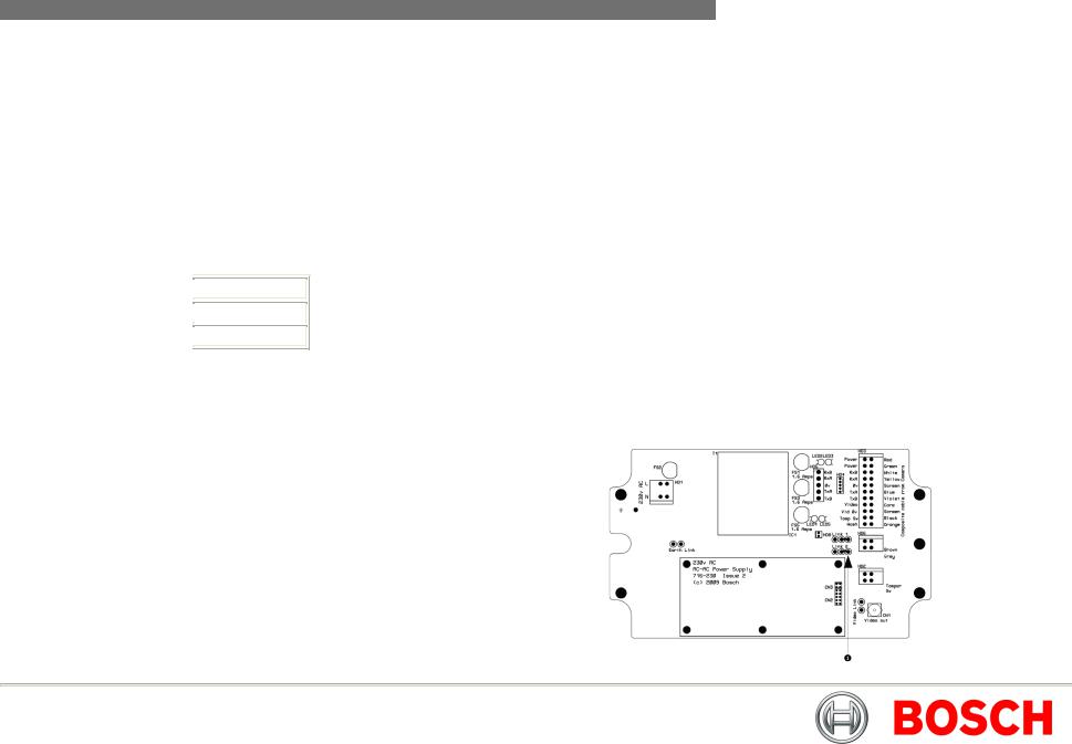
Commissioning the MIC 412 with heater option fitted
These instructions are applicable to the MIC non-IR power supplies only. There are two links on the power supply printed circuit board which must be changed to allow heater operation. Please do the following to enable the heaters to function:
1.Disconnect the power supply from the power source.
2.Locate the PCB links next to HD6 (item 1) the default setting is 0 V.)
Bosch Security Systems |
Issue 8 |

MIC412TI and MIC412TF Camera | Installation and Operation Manual
3.Break the two wire links and remove any excess solder.
4.Solder the wire links using a soldering iron and TCW link wire from the left hand pads to the middle pads.
5.The power supply will now deliver +18vac to HD6.
6.Connect the heater wires (brown and gray) from the shielded composite cable to the HD6 terminal as labelled on the PCB.
7.The heaters are thermostatically controlled and will automatically turn on at +5°C (+41°F) and turn off at +15°C (+59°F).
8.Check all connections, re-seal the PSU enclosure and re-apply power.
EN | 19
Fitting the optional Sunshield
The MIC412 Sunshield is designed to provide additional protection against direct solar radiation, it is a two (2) part moulding and comes supplied with eight (8) stainless steel bosses and eight (8) M3 washers and retaining screws. The sunshield is fitted in the following manner:-
1.Remove the four (4) retaining bolts from the lid of the MIC 412, DO NOT remove the lid as this will void the warranty.
2.Replace each retaining screw with one of the stainless steel bosses and tighten using a flat head screwdriver in the slot on top of each boss.
3.When all four (4) bosses have been fitted, line up the holes in the sunshield with the bosses.
4.Fix the sunshield to the bosses using the M3 stainless steel washers and screws.
5.Rotate the MIC412 under power (Do not rotate by hand) and repeat the procedure above on the lower lid of the MI C412.
Bosch Security Systems |
Issue 8 |

MIC412TI and MIC412TF Camera | Installation and Operation Manual
CHAPTER 4 Configuring the MIC 412 Camera
Connecting the MIC 412 to the PC
The MIC412 can be connected to a PC’s serial port via a RS232/RS422 adaptor unit; this will generally be assigned to Comm Port 1.
Suitable serial port adaptor units are the Greenwich RS232/RS422 adaptor unit (Farnell 778-758, RS No: 201-758), the KK systems K2-ADE RS232 to RS485/422 adaptor or the MIC-USB485CVTR (485 to USB Converter) for PC’s without a serial port.
Connecting the Greenwich Adaptor
To connect the Greenwich serial adaptor to the PC you will also need a 9 pin D female to 25 pin D male RS232 compatible adaptor cable. A suitable cable is Farnell 960-573 or RS Part No: 202-644.
The adaptor should be set to DCE mode and the power supply connected.
Connections from the Greenwich adaptor to the MIC412 power supply are as follows
Table G – Connecting the Greenwich Adaptor
|
|
|
|
|
|
|
|
|
Adaptor Connections |
|
|
HD4 |
|
|
|
|
|
|
|
|
|
|
|
|
|
|
|
|
|
F 778-758. |
|
|
Connection and wire |
|
|
|
|
|
color. |
|
|
|
|
|
|
|
|
|
|
|
|
|
|
|
|
|
|
DATA OUT 6-3+ |
|
|
RXB White |
|
|
|
|
|
|
|
|
|
|
DATA OUT 5-4- |
|
|
RXA Yellow |
|
|
|
|
|
|
|
|
|
|
SCREEN |
|
|
0v |
|
|
|
|
|
|
|
|
|
|
DATA IN 4-5- |
|
|
TXA Blue |
|
|
|
|
|
|
|
|
|
|
DATA IN 3-6+ |
|
|
TXB Violet |
|
|
|
|
|
|
|
|
EN | 20
The connections can be tested by selecting the DETECT button in CamSet and checking to see if the window below this button displays the address and software version No of the camera being tested.
Should a problem be encountered then connect the MIC412 screen wire (0v) to the pc chassis with a separate piece of wire to ensure 0v continuity
Connecting the KK systems K2-ADE RS232 to RS485/422 Adaptor
This unit is self powered and can be plugged directly into the PC serial port. RS485 two wire mode.
Connections and Dip switches settings for 2-wire mode should be made as follows:-
Table H – K2-ADE Adaptor connections
|
|
|
|
|
|
Adaptor Connections |
|
HD4 |
|
|
|
|
|
|
|
|
|
|
|
|
K2-ADE |
|
Connection. |
|
|
|
|
|
|
|
Pin 3 |
|
RXB White |
|
|
|
|
|
|
|
Pin 9 |
|
RXA Yellow |
|
|
|
|
|
|
|
Pin 5 |
|
0v |
|
|
|
|
|
|
|
Not required |
|
TXA Blue |
|
|
|
|
|
|
|
Not required |
|
TXB Violet |
|
|
|
|
|
|
Bosch Security Systems |
Issue 8 |
MIC412TI and MIC412TF Camera | Installation and Operation Manual
With all the above set up, when Camset is running and the serial port selected, set the Camera Interface Controls to the following:-
Table I – Camera Interface Control Settings
|
|
|
|
|
DIP Switch |
|
Setting |
|
|
|
OFF |
|
|
|
|
|
Sw 1 |
|
|
|
|
|
OFF |
|
Sw 2 |
|
|
|
|
|
OFF |
|
Sw 3 |
|
|
|
|
|
ON |
|
Sw 4 |
|
|
|
|
|
OFF |
|
Sw 5 |
|
|
|
|
|
ON |
|
Sw 6 |
|
|
|
|
|
|
If a notebook PC is used, which sometimes lacks a serial port, then a RS485 to USB converter such as the MIC-USB485CVTR can be used instead, this would typically be mapped to Comms port 3 or 4.
|
|
|
|
|
EN | 21 |
||
|
Connecting the MIC-USB485CVTR, USB to RS485 Converter |
||||||
|
|
|
|
|
|
|
|
|
Camset Tabs |
2 Wire RS485 |
4 Wire RS422 |
||||
|
|
|
|
|
|
|
|
|
|
|
|
|
|
|
|
|
Comms 1 |
|
Selected |
|
Selected |
|
|
|
|
|
|
|
|
|
|
|
|
|
|
|
|
|
|
|
Interface |
|
2 Wire |
|
4 Wire |
|
|
|
|
|
|
|
|
|
|
|
|
|
|
|
|
|
|
|
RTS |
|
Off |
|
On |
|
|
|
|
|
|
|
|
|
|
|
|
|
|
|
|
||
|
Baud |
|
9600 |
|
9600 |
|
|
|
|
|
|
|
|
|
|
|
|
|
|
|
|
|
|
The MIC-USB485CVTR is a USB to RS485 signal converter that allows PCs without a serial port to connect directly to the MIC400 series camera via the telemetry connection (HD4) in the power supply, the MIC-USB485CVTR can also be used to connect a PC to any other RS485 device.
The MIC-USB485CVTR has been designed to work with all functions in Universal Camset and to be backwards compatible with legacy version of Camset although full compatibility is not guaranteed.
The MIC-USB485CVTR should be connected to the telemetry header (HD4) of the MIC power supply with Standard Twisted Pair cable such as Belden 8760.
Bosch Security Systems |
Issue 8 |
 Loading...