


Water heaters for use with Natural and L.P.G.
GWH 425 EF
Flow Modulated with Electronic Ignition and Power Venting
Suitable for heating potable water only - Not approved for space heating purposes (Intended for variable flow applications with steady cold water inlet temperatures)

 WARNING: Improper installation, adjustment, alteration, service or maintenance can cause injury or property damage. Refer to this manual. For assistance or additional information consult a qualified installer, service agency or the gas supplier.
Upon completion of the installation, these instructions should be handed to the user of the appliance for future reference.
In the Commonwealth of Massachusetts this product must be installed by a licensed plumber or gas fitter.
FEATURING: Electronic Ignition and Power Venting
WARNING
If the information in this manual is not followed exactly. A fire or explosion may result causing property damage, personal injury or death.
FOR YOUR SAFETY
Do not store or use gasoline or other flammable, combustible or corrosive vapors and liquids in the vicinity of this or any other appliance.
WHAT TO DO IF YOU SMELL GAS
-Close gas valve. Open windows.
-Do not try to light any appliance.
-Do not touch any electrical switch; do not use any phone in your building.
-Immediately call your gas supplier from a neighbor’s phone. Follow the gas supplier’s instructions.
-If you cannot reach your gas supplier, call the fire department.
-Installation and service must be performed by a qualified installer, service agency or the gas supplier.
TABLE OF CONTENTS
Specifications ............................................................... |
Page 3 |
Rules for safe operation ............................................. |
Page 5 |
Locating the Heater .................................................... |
Page 5 |
Combustion Air Requirements .................................. |
Page 6 |
Mounting the Heater ................................................... |
Page 7 |
Venting the Heater ...................................................... |
Page 8 |
Gas Connections ...................................................... |
Page 11 |
Water Connections ................................................... |
Page 13 |
Electrical Connections ............................................. |
Page 14 |
Safety before turning on the heater ...................... |
Page 15 |
Lighting and Operating instructions ...................... |
Page 15 |
Setting water temperature ....................................... |
Page 15 |
Maintenance & Service ............................................ |
Page 16 |
Trouble Shooting ......................................................... |
Page 17 |
Diagram of AquaStar ................................................ |
Page 20 |
Components and Parts List ..................................... |
Page 21 |
2 |
6 720 607 017 |

Principle of Operation:
When a hot water faucet is opened, the flow of water through the heater causes the gas valve to open. At the same time a microswitch is activated which sends a spark to the pilot. The flame sensor confirms that the pilot has been lighted and allows the first two burners to ignite. The flame sensor confirms correct activation and all burners ignite. The pilot goes out. The power exhaust system runs as long as the burners are on. The heat exchanger coils absorb the heat generated by the burners and transfer heat to the water. When the hot water faucet is shut off, the gas valve automatically closes and the burners turn off, followed immediately by the exhaust system. Your hot water faucet is an ignition key to turn on the water heater, giving you control over your hot water energy use. Every time you turn off your hot water faucet, the energy consumption for hot water returns to zero.
FEATURES
-Electronic Pilot Ignition
-On/Off switch to activate system
-Power Venting with safety shutoff
-High Quality Materials for Long Working Life.
-Copper heating coils for endless supply of hot water.
-Burner output proportional to hot water flow demand for maximum energy efficiency.
-Safety flame sensor at pilot burner.
-Automatic overheating protection shut-off sensor.
-Stainless steel burners with stabilized blue flame.
-Built-in corrosion resistant power venter.
-Compact space saver: mounts on a wall with two hooks.
-Easily removable one-piece cover.
-Easy one person installation.
-Adjustable water flow restrictor to ensure that water flow demand will not exceed the heating capacity of the heater.
UNPACKING THE 425 EF HEATER
425 EF LP and 425 EF NG Specifications
|
425EF NG |
425 EF LP |
|
|
|
max. |
130 000 Btu/hr |
125 000 Btu/hr |
Gas input |
|
|
|
|
|
min. |
28 000 Btu/hr |
28 000 Btu/hr |
|
|
|
Water Connection 1/2” Thread fitting NPT
H x W x D 29 3/4” x 18 1/4” x 8 3/4" |
|
Vent 4” |
|
Gas Connection 1/2” NPT thread |
|
Min. Water Pressure 18 Psi |
|
Max. Water Pressure 150 Psi |
|
Shipping Weight 50.6 LB |
|
Net Weight 44 LB |
|
2.0 GPM at 90° rise |
|
4.0 GPM at 45° rise |
|
Min. Water Flow 1/2 gal/min |
|
120V/60Hz 1.2 Amps |
|
LP GAS Supply Pressure |
min. 11” W.C. |
(before 425 EF regulator) |
max.14” W.C.* |
Required LP GAS pressure at inlet |
|
tap while 425 EF is operating: |
10.5” W.C. |
LP GAS Burner Manifold pressure while
425 EF is operating at maximum input: 9.9” W.C.
Natural Gas Supply Pressure |
min.: 7” W.C. |
(before 425 EF regulator) |
max.: 14”W.C.* |
Required Natural Gas Pressure at |
|
inlet tap while 425 EF is operating: |
5.7”W.C. |
Natural Gas Burner Manifold pressure while
425 EF is operating at maximum input: 5.38” W.C.
* Inlet gas pressure before 425 EF regulator must not exceed this value. Pressure may need to be adjusted for high altitudes, see page 11.
This heater is packed securely. The box includes one water connection fitting, a control knob with collar, a gas pressure regulator, a pressure relief valve, an incandescent particle tray, two hooks for hanging the heater, this manual and a warranty registration card. Do not lose this manual as there is a charge for replacement. Please complete and return the enclosed warranty registration card. The FXHOOD horizontal vent terminator is supplied separately from the 425EF water heaters. There is a set of installation instructions in the FXHOOD box.
6 720 607 017 |
3 |
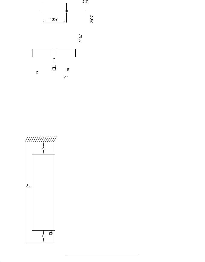
FRONT VIEW |
SIDE VIEW |
MINIMUM INSTALLATION CLEARANCES FROM COMBUSTIBLE AND NON COMBUSTIBLE MATERIALS FOR ALCOVE OR CLOSET INSTALLATIONS
* On a combustible wall surface the unit should be mounted away from the wall to provide adequate clearance of the vent pipe.
See page 5 for instructions.
MODEL 425 EF
4 |
6 720 607 017 |
GENERAL RULES TO FOLLOW
FOR SAFE OPERATION
1.You should follow these instructions when you install your heater. In the United States: The installation must conform with local codes or, in the absence of local codes, the National Fuel Gas Code ANSI Z223.1/NFPA 54.
In Canada: The Installation should conform with CGA B149.(1,2) INSTALLATION CODES and /or local installation codes.
2.Carefully plan where you install the heater. Correct combustion air supply and flue pipe installation are very important. If not installed correctly, fatal accidents can be caused by lack of air, carbon monoxide poisoning or fire.
3.The place where you install the heater must have enough ventilation. The National Fire Codes do not allow gas fired water heater installation in bathrooms, bedrooms or any occupied rooms normally kept closed. See the section below on locating the heater.
4.You must install your heater so that the venting complies with all requirements. See section on Venting the Heater, pages 6 and 7.
5.The appliance must be disconnected from the gas supply piping system during any pressure testing at pressures in excess of 1/2 Psig (3.5 kPa).
The appliance must be isolated from the gas supply piping during any pressure testing of the gas supply piping system at test pressures in excess of 1/2 Psig (3.5Kpa). The appliance and its gas connection must be leak tested before placing the appliance in operation.
6.Keep water heater area clear and free from combustibles and flammable liquids. Do not locate the heater over any material that might burn. Do not install heater over carpeting.
7.Correct gas pressure is critical for the optimum operation of this heater (see specifications on page 2 and chart on page 9). Gas piping must be sized to provide the required pressure at the maximum output of the heater. Check with your local gas supplier, and see the section on connecting the gas supply.
8.Should overheating occur or the gas supply fail to shut off, turn off the gas supply at the manual gas shut off valve on the gas line.
9.Do not use this appliance if any part has been under water. Immediately call a qualified service technician to inspect the appliance and to replace any part of the control system and any gas control that has been under water.
10.When installed, the appliance must be electrically grounded in accordance with local codes or, in the absence of local codes, in accordance with the National Electrical Code ANSINFPA 70 and/or the CSA 22.1 Electrical Code.
PROPER LOCATION FOR INSTALLING YOUR HEATER
Carefully select the location of your new heater. For your safety and for proper heater operation, you must provide an abundant supply of combustion air and a proper venting installation.
The heater may still operate even when improperly vented. It will, however, be less efficient and could eventually damage the heater. It could even result in human sickness or death due to oxygen deprivation and carbon monoxide poisoning. Before installing the unit, be certain you have the correct heater for your type of Gas – Propane or Natural Gas. Identification labels are found on the shipping box, and on the rating plate which is located on the right side panel of the cover. Also, each burner orifice is stamped with a number (79 for LPG and 120 for Natural Gas).
Follow the guidelines below:
1.National building codes require that you do not install this appliance in bathrooms, bedrooms, unvented closet or any occupied rooms normally kept closed.
2.Simultaneous operation of other appliances such as exhaust fans, ventilation systems, clothes dryers, fireplaces or wood stoves could create a vacuum effect in your home which could cause dangerous combustion by-products to spill back into your home rather than venting to the outside through the flue. Confirm that your 425 EF is venting properly when all these other appliances are running. See page 6 to test venting performance.
Do not obstruct the flow of combustion air to the appliance. This appliance is power vented and uses room air. Note: Electrical power is required to operate the power exhaust. Proper air supply to the appliance is essential.
If installed near a clothes dryer it is very important that the dryer be properly vented. Failure to properly vent a dryer could result in a gradual accumulation of lint on the water heater fin coils and burners, leading to a dangerous condition of vent blockage and poor, unsafe combustion.
3. Your hot water lines should be kept short to save energy. It is always best to have hot water lines insulated.
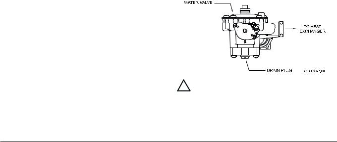
 WARNING: DO NOT INSTALL IN AN AREA WHERE IT COULD FREEZE. This heater is neither designed for nor approved for outside installation. Drain the heater entirely if freezing temperatures are anticipated in area where heater is installed by disconnecting both the inlet and outlet water connections from the heater (disconnect the outlet flex line from where it connects to the copper heat exchanger). Additionally, remove the drain plug under the water valve. See Fig 1.
Fig. 1 - Water heater drain plug
 WARNING: Flammable materials, gasoline, pressurized containers, or any other items or articles that are potentially fire hazards must NOT be placed on or adjacent to the heater. The appliance area must be kept free of all combustible materials, gasoline and other flammable vapors and liquids.
6 720 607 017 |
5 |
COMBUSTION AIR REQUIREMENTS
The 425 EF water heater holds cold water in its copper heat exchanger and brass water valve when not in use. Because of this, any cold air that comes in through the unit’s vent pipe is capable of freezing these components. This Installation Manual specifies the vent length requirements and the amount of combustion air required for this unit. When all requirements are followed, the unit will operate properly and safely. However, there may still be a risk of freezing due to negative draft if all the combustion appliances in the area are not being supplied with a sufficient amount of make-up air. A wood stove or furnace may pull combustible air through the 425 EF vent pipe, leaving the cold infiltrating air capable of freezing the cold water in the 425 EF heat exchanger. To prevent this the FXHOOD horizontal vent terminator, which is supplied separately with the water heater, needs to be installed on the end of the horizontal vent run (see page 9). The FXHOOD is a CSA approved vent terminator for the 425 EF and has a built in back draft flapper.
Observe the following instructions concerning combustion air.
Appliances located in unconfined spaces:
a)An unconfined space is one whose volume is greater than 50 cubic feet per 1000 Btu per hour of the combined rating of all appliances installed in the space. That would be 6500 cubic feet for the 425 EF alone.
b)In unconfined spaces in buildings of conventional frame, masonry, or metal construction, infiltration is normally adequate to provide air for combustion, ventilation, and dilution of flue gasses.
Appliances located in confined spaces: The confined space must be provided with two permanent openings, one commencing within 12 inches of the top and one commencing within 12 inches of the bottom of the enclosure. Each opening must have a minimum free area of one square inch per:
—1000 Btu/hr if all air is taken from inside the building.
—2000 Btu/hr if all air is taken from the outside by horizontal ducts.
—4000 Btu/hr if all air is taken from the outside by direct openings or vertical ducts.
Or the confined space must be provided with one permanent opening or duct that is within 12 inches of the ceiling of the enclosure. This opening must have a minimum free area of one square inch per:
—3000 Btu/hr if all air is taken from the outside by a direct opening or vertical duct.
Louvers, grills and screens have a blocking effect. If the effective free area is not known, assume it is 20 % to 25% of the total opening for wood louvers and 60 % to 75% for metal louvers. Refer to the National Fuel Gas Code for complete information. In buildings of tight construction all air should be taken from outside.
This product is not approved for manufactured homes (mobile home), recreational vehicles (RV) or boats. Reference ANSI Z21.10.3.
This product is neither designed or approved for outside installations.
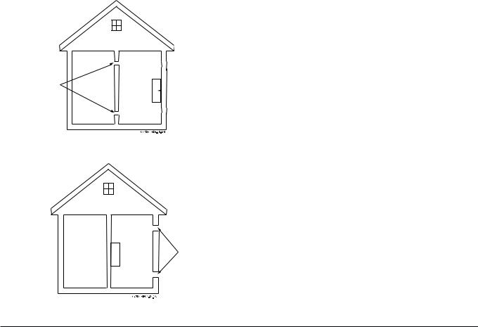
CLEARANCES
The 425 EF is design certified for installation on a combustible wall and for installation in an alcove or closet with the minimum clearances to combustible and non - combustible construction listed below
A.Top 12 inches (305 mm)
B.Front 4 inches (102 mm)
C.Back 0 inches*
D.Sides 4 inch (102mm)
E.Bottom 12 inches (305 mm)
Air Vents
(10 ¾ X 10 ¾ in. each) |
|
425 EF |
|
* On a combustible wall surface the unit should be mounted away from the wall to provide adequate clearance of the vent pipe. Clearance from the vent pipe is dependent upon the clearance rating of the venting material used. See VENTING section.
425 EF  Air Vents
(5 ½ X 5 ½ in. each)
6 |
6 720 607 017 |
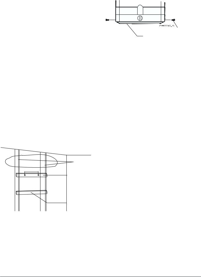
MOUNTING INSTALLATION
The 425 EF is design certified for mounting on a wall. Secure the two L shaped hooks, which are provided with heater, to a wall surface. Place them 13 ¼” apart as shown in Fig 2.
Do not install this appliance on a carpeted wall or over floor covering which is combustible, such as carpet. The heater must be mounted on a wall using appropriate anchoring materials. If wall is a stud wall sheathed with plasterboard, it is recommended that support board(s) either 1x4’s or 1/2" (minimum) plywood first be attached across a pair of studs and then the heater should be attached to the support boards. See Fig 2.
NOTE: Additionally the 425 EF should be spaced away from any combustible wall surface to provide the necessary clearance that the venting material specifies must be maintained between the vent pipe and a combustible surface. See VENTING section. Also, review the FXHOOD horizontal vent terminator instruction sheet (provided with the FXHOOD) prior to installation.
In earthquake-prone zones, CEC recommends that installers use a large washer and lag screw through the existing holes used to hang the heater to affix the upper third of the heater to the mounting board. To affix the lower third of the heater, CEC recommends that two new holes be drilled in the heater’s frame, each one 16 inches below the top two holes, and that washers and lag screws be used to secure the lower portion of the heater to a spacing board.
Expansion and contraction of piping due to changing water temperature in the pipes imparts movement to the heater which, if mounted directly to a brittle, friable board, such as plasterboard, can cause failure of mounting.
The incandescent particle tray (shipped loose in the carton with the water heater) must be attached at the bottom of the water heater front cover at the time of installation. Use the screws provided. See figure 3.
SCREWS
INCANDESCENTPARTICLE TRAY
Fig. 3 - Incandescent Particle Tray Illustration
WALL STUDS
13 ¼”
SUPPORT BOARD
1” X 4”
SPACE BOARD
Fig. 2 - Mounting the Heater
6 720 607 017 |
7 |
VENTING
 WARNING: Do not reduce the vent pipe size and do not common vent with any other vented appliance or stove.
This appliance must be vented horizontally to the outside with a sealed 4” single wall vent pipe. The appliance’s flue gasses are under positive pressure and must travel through a single wall 4” pipe that is sealed gas tight. The 4” single wall vent pipe can be either stainless steel (AL29-4C) or galvanized steel with at least 26 gauge. CEC recommends the use of stainless steel vent pipe (which is equipped with sealing gaskets) for ease of installation and durability. When using galvanized vent pipe a minimum of 4 sheet metal screws per connection must be installed and all seams must be sealed with an approved high temperature silicone sealant. The vent system must be gas tight. See Fig. 4 for suggested venting installation diagrams.
The 425EF shall not be vented in combination with any other appliance. This appliance may only be vented horizontally with a dedicated sealed single wall vent. The 425EF shall not be vented into masonry chimneys or existing vertical vents of any material.
CAUTION: 425EF vent system must be installed by a qualified agency in accordance with these instructions. If improperly installed a hazardous condition such as explosion or Carbon Monoxide poisoning could result. Controlled Energy Corporation will not be responsible for improperly installed appliances.
Establish vent clearances that comply with vent manufacturer’s specifications. In all cases follow local codes. See table below.
The vent diameter must be 4”. The appliance should be located as close to the point of termination as possible (see Fig. 5 for locating the terminator). The vent system should be as straight and short as possible. The vent pipe must be 4” single wall stainless steel (AL29-4C) or galvanized steel pipe of 26 minimum gauge. Maximum vent length is 15
feet (4.6 m) with two 90-degree elbows. Subtract 5 feet from the total vent length for each additional 90-degree elbow used. No more than four 90-degree elbows may be used. Any short vertical portion of vent pipe used in the vent system shall be considered part of the allowable 15 feet (4.6 m) maximum run. Support the vent run at 4 foot intervals with overhead hangers. Horizontal sections of vent must rise ¼” for every foot of horizontal length. Any vent section greater than 45 degrees is considered and elbow.
Note: Single wall pipe should not be used in concealed, unoccupied or unheated locations. Listed thimbles or collars are necessary to pass through wall partitions. If the vent system passes through combustible areas where the vent clearance requirements cannot be maintained, it is permissible to chase straight sections of sealed 4 inch single wall vent through 5 inch (or greater) Type-B vent. The distance to combustibles using this chase technique is 1 inch. Note: Type-B vent should never be used as the actual vent system for the 425EF, as it is not gas tight.
Freeze Warning:
As mentioned on Page 6, negative air pressure in cold climates will cause a reverse airflow in the vent system that can freeze and damage the 425 EF heat exchanger when not in use. To prevent this the FXHOOD horizontal vent terminator, which was supplied separately with the water heater, needs to be installed on the end of the horizontal vent run (see page 9). The FXHOOD is a CSA approved vent terminator for the 425 EF and has a built in back draft flapper.
Flue Gas Sensor:
The 425 EF is equipped with a Flue Gas Sensor; it’s mounted on the left side of the draft diverter (Flue Gas Sensor - #33 on page 21). Before leaving the installation site verify proper Flue Gas Sensor operation by temporarily blocking termination outlet. Once blocked then operate the heater, the unit should shut down within 1-3 minutes when the flue gases are blocked. You must reset the electrical power to the heater after this safety test has been conducted, otherwise the unit will not operate.
The flue gas exhaust temperature on the 425 EF is 356°F (180°C)
Venting Material |
Exhaust vent |
Exhaust vent maximum |
Options |
diameter |
distance |
|
|
|
Single wall stainless |
|
15 feet (4.6 m) with two |
steel (AL29-4C) |
4 inch |
elbows. Less 5 feet for |
sealed vent pipe |
|
each additional elbow. |
Single wall galvanized |
|
|
vent pipe (min. 26 |
|
15 feet (4.6 m) with two |
gauge and sealed |
4 inch |
elbows. Less 5 feet for |
with high temperature |
|
each additional elbow. |
silicone) |
|
|
|
|
|
|
Vent pipe within an |
Vent pipe within an |
|
unenclosed space |
enclosed space |
|
|
|
Clearances |
*See manufacturer's |
*See manufacturer's |
specifications |
specifications |
|
from venting |
|
|
|
|
|
material |
|
|
|
6 inches |
NOT PERMISSIBLE |
|
|
|
*Stainless steel (AL29-4C) vent pipe manufacturer's are Z-Flex, Protech and Heat Fab. The manufacturer's specified clearances are identified on the venting material. NOTE: clearance distances are variable depending if the vent pipe is installed in an enclosed or unenclosed space, the exhaust flue gas temperature and the orientation of the vent pipe.
8 |
6 720 607 017 |
 Loading...