


 Loading...
Fire Alarm Control Panels
FPD-7024
en Installation and Operation Manual

Fire Alarm Control Panels Table of Contents | en 3
Table of contents
1 |
Notices |
6 |
1.1 |
FCC Compliance Notice |
6 |
1.2 |
FCC Phone Connection to Users |
6 |
1.3 |
Industry Canada Notice |
7 |
1.4 |
Trademarks |
7 |
2 |
Overview |
8 |
2.1 |
System overview |
8 |
2.2 |
Components |
9 |
2.2.1 |
On-board conventional points |
9 |
2.2.2 |
Off-board addressable points (with D7039 Multiplex Expansion Module) |
9 |
2.2.3 |
Enclosure Housing |
10 |
2.2.4 |
Remote LCD Keypads |
10 |
2.2.5 |
Remote LED Annunciators |
10 |
2.2.6 |
D7032 - use with the D7030X |
10 |
2.2.7 |
Communicator |
12 |
2.2.8 |
Users |
13 |
2.2.9 |
Lightning protection |
13 |
2.2.10 |
Battery backup calculation |
13 |
2.2.11 |
Required batteries for existing load |
16 |
2.2.12 |
Compatible devices |
17 |
2.3 |
Parts List |
19 |
3 |
Fire Safety |
20 |
3.1 |
Smoke detector layout |
20 |
3.1.1 |
General considerations |
20 |
3.1.2 |
Family residences |
20 |
3.2 |
Having and practicing an escape plan |
21 |
4 |
Installation |
22 |
4.1 |
Installation guide for UL Listed systems |
22 |
4.1.1 |
FPD 7024 UL Listings |
22 |
4.1.2 |
Installation considerations |
22 |
4.1.3 |
UL requirements |
22 |
4.2 |
Installing the enclosure |
25 |
4.3 |
Installing the FPD 7024 |
26 |
4.4 |
Installing optional equipment |
27 |
5 |
Connection |
29 |
5.1 |
FACP terminal connection |
29 |
5.2 |
Power supply connection |
33 |
5.3 |
Option bus wiring requirements |
34 |
6 |
System Operation |
36 |
6.1 |
Modes of Operation |
36 |
6.1.1 |
Normal |
36 |
6.1.2 |
Off-normal Displays |
36 |
6.1.3 |
Acknowledge |
36 |
6.1.4 |
Alarm |
36 |
6.1.5 |
Supervisory |
36 |
6.1.6 |
Trouble |
37 |
6.1.7 |
Fire Silence/Reset |
37 |
Bosch Security System, Inc. |
Installation and Operation Manual |
2012.08 | 04 | F01U008458 |

4 en | Table of Contents Fire Alarm Control Panels
6.2 |
Basic System Use |
38 |
6.2.1 |
Function keys |
38 |
6.2.2 |
Selecting menu items |
38 |
6.2.3 |
After a Main Menu item is selected |
38 |
6.2.4 |
Returning to an earlier screen |
38 |
6.2.5 |
Entering data |
38 |
6.2.6 |
Drill |
38 |
6.2.7 |
Disable |
38 |
6.2.8 |
History |
39 |
6.2.9 |
Remote Programming |
40 |
6.3 |
Keypads |
40 |
6.3.1 |
Built-in keypad |
40 |
6.3.2 |
FMR-7033 keypad |
42 |
6.4 |
Testing |
43 |
6.4.1 |
Walk test |
43 |
6.4.2 |
Communicator test |
43 |
6.4.3 |
Battery/NAC circuits test |
44 |
6.4.4 |
Activate ouputs test |
44 |
6.4.5 |
Zone input level test |
44 |
6.4.6 |
Addressable point test (MUX test) |
44 |
6.4.7 |
Sensitivity test |
45 |
6.5 |
Point/Zone Mapping |
45 |
6.6 |
Personal Identification Numbers (PINs) |
47 |
6.7 |
Communicator Operation |
47 |
7 |
|
|
Programming |
49 |
|
7.1 |
Programming features |
49 |
7.2 |
Point programming |
50 |
7.3 |
Alpha programming |
51 |
7.4 |
Format programming |
53 |
7.5 |
Program menu tree |
55 |
7.6 |
Shortcuts |
56 |
7.7 |
Remote programming |
57 |
8 |
|
|
Control Panel Programming |
59 |
|
8.1 |
PROG TIME |
59 |
8.1.1 |
Program time |
59 |
8.1.2 |
Automatic test |
59 |
8.1.3 |
Daylight saving time |
60 |
8.2 |
SECURITY |
60 |
8.2.1 |
Personal Identification Numbers (PINs) |
61 |
8.2.2 |
Authority |
61 |
8.3 |
PROG SYSTEM |
62 |
8.3.1 |
Program timers |
62 |
8.3.2 |
AC line synch |
64 |
8.3.3 |
Option bus |
64 |
8.3.4 |
PIN required |
65 |
8.3.5 |
NAC silence mode |
66 |
8.3.6 |
Remote programming |
67 |
8.4 |
PROG INPUTS |
67 |
8.4.1 |
Point number |
67 |
2012.08 | 04 | F01U008458 |
Installation and Operation Manual |
Bosch Security System, Inc. |

Fire Alarm Control Panels Table of Contents | en 5
8.4.2 |
Point function |
70 |
8.4.3 |
Point copy |
72 |
8.5 |
PROG OUTPUTS |
73 |
8.5.1 |
Programming NACs |
73 |
8.5.2 |
Programming relays |
76 |
8.6 |
PROG ACCOUNTS |
77 |
8.6.1 |
Phone Numbers/IP Addresses |
78 |
8.6.2 |
Phone Control |
82 |
8.6.3 |
Report Steering |
83 |
8.6.4 |
Ring Count |
84 |
8.6.5 |
Communication Tries |
85 |
8.6.6 |
Machine Bypass |
85 |
8.6.7 |
ALT. COMM |
85 |
8.7 |
PROG FORMATS |
85 |
8.7.1 |
4/2 Zone Report |
86 |
8.7.2 |
4/2 Report Codes |
87 |
8.7.3 |
BFSK Report Codes |
88 |
8.8 |
HISTORY DEFAULTS |
88 |
8.8.1 |
Clear History |
88 |
8.8.2 |
Default EE |
89 |
8.8.3 |
Alternate 4/2 Codes |
89 |
8.9 |
Program MUX |
89 |
8.9.1 |
MUX Edit |
90 |
8.9.2 |
MUX Program |
90 |
8.9.3 |
MUX Bus Type |
92 |
8.9.4 |
AUTO PROGRAM |
93 |
8.9.5 |
Removing MUX Devices |
96 |
9 |
|
|
Specifications |
98 |
|
10 |
|
|
Appendices |
99 |
|
10.1 |
Appendix A: Abbreviations on Control Panel Display |
99 |
10.2 |
Appendix B: Control Panel Display Descriptions |
100 |
10.3 |
Appendix C: Reporting Summary for Fire Communicator |
102 |
10.4 |
Appendix D: Programming Defaults List |
110 |
10.5 |
Appendix E: Phone Monitor Troubleshooting |
118 |
10.5.1 |
COMM FLT/DATA LOST |
118 |
10.5.2 |
Trouble Phone |
119 |
Bosch Security System, Inc. |
Installation and Operation Manual |
2012.08 | 04 | F01U008458 |

6 en | Notices Fire Alarm Control Panels
1 |
Notices |
1.1 |
FCC Compliance Notice |
|
This equipment was tested and found to comply with the limits for a Class A digital device, |
|
pursuant to Part 15 of the FCC Rules. These limits are designed to provide reasonable |
|
protection against harmful interference in a residential installation. This equipment generates, |
|
uses, and can radiate radio frequency energy, and if not installed and used in accordance with |
|
the instructions, might cause harmful interference to radio communications. There is no |
|
guarantee that interference will not occur in a particular installation. If this equipment does |
|
cause harmful interference to radio or television reception, that can be determined by turning |
|
the equipment off and on, the user is encouraged to try to correct the interference by one or |
|
more of the following measures: |
|
– Re-orient or relocate the receiving antenna. |
|
– Increase the separation between the equipment and the receiver. |
|
– Connect the equipment into an outlet on a circuit different from that to which the |
|
receiver is connected. |
|
– Consult the dealer or an experienced radio or TV technician for help. |
1.2 |
FCC Phone Connection to Users |
|
This control panel complies with Part 68 of the FCC rules. |
|
On the inside of the enclosure is a label that contains, among other information, the ringer |
equivalence number (REN) for this equipment. You must, upon request, provide this information to your local telephone company.
The REN is useful to determine the quantity of devices that can be connected to your telephone line and still have all of those devices ring when your telephone number is called. In most, but not all areas, the sum of the RENs of all devices connected to one line should not exceed five. To ascertain the number of devices that you can connect to your line, contact your local telephone company to determine the maximum REN for your local calling area.
This equipment can not be used on coin service provided by the telephone company. Do not connect this control panel to party lines. If this equipment causes harm to the telephone network, the telephone company might discontinue your service temporarily. If possible, they will notify you in advance. But if advance notice isn’t practical, you will be notified as soon as possible.
You will be informed of your right to file a complaint with the FCC. The telephone company might make changes in its facilities, equipment, operations, or procedures that could affect the proper functioning of your equipment. If they do, you will be notified in advance to give you an opportunity to maintain uninterrupted telephone service.
If you experience trouble with this equipment, contact the manufacturer for information on obtaining service or repairs.
The telephone company might ask that you disconnect this equipment from the network until the problem is corrected or until you are sure that the equipment is not malfunctioning. The manufacturer, not the user, must make the repairs to this equipment. To guard against accidental disconnection, there is ample room to mount the telco jack inside of the control panel cabinet.
The operation of this control panel might also be affected if events such as accidents or acts of God cause an interruption in telephone service.
2012.08 | 04 | F01U008458 |
Installation and Operation Manual |
Bosch Security System, Inc. |

Fire Alarm Control Panels Notices | en 7
1.3 Industry Canada Notice
The Industry Canada label identifies certified equipment. This certification means that the equipment meets certain telecommunications network protective, operational, and safety requirements. Industry Canada does not guarantee the equipment will operate to the user’s satisfaction.
Before installing this equipment, users should ensure that it is permissible to be connected to the facilities of the local telecommunications company. The equipment must also be installed using an acceptable method of connection. The customer should be aware that compliance with the above conditions might not prevent degradation of service in some situations. Repairs to certified equipment should be made by an authorized Canadian maintenance facility designated by the supplier. Any repairs or alterations made by the user to this equipment, or equipment malfunctions, might give the telecommunications company cause to request the user to disconnect the equipment.
Users should ensure for their own protection that the electrical ground connections of the power utility, telephone lines, and internal metallic water pipe system, if present, are connected together. Users should not attempt to make such connections themselves, but should contact the appropriate electric inspection authority, or electrician.
1.4 Trademarks
All hardware and software product names used in this document are likely to be registered trademarks and must be treated accordingly.
Microsoft, Windows, and Windows NT are either registered trademarks or trademarks of Microsoft Corporation in the United States and/or other countries.
CYCOLOY is a registered trademark of Sabic Plastic.
POLYLAC is a registered trademark of CHI MEI Industrial Corporation, LTD.
CleanMe is a trademark of GE Interlogix, Inc. in the United States and/or other countries.
Bosch Security System, Inc. |
Installation and Operation Manual |
2012.08 | 04 | F01U008458 |
8 en | Overview Fire Alarm Control Panels
2 |
Overview |
|
2.1 |
System overview |
|
|
The FPD 7024 Fire Alarm Control Panel is a fully integrated hard-wire fire alarm system. It can |
|
|
support four input points (expandable to 255 using D7039 Multiplex Expansion Module and |
|
|
the FPC 7034 Four-Point Expander) and 16 individual users (expandable to 100 with the |
|
|
D7039). The control panel has a built-in LCD keypad. Up to four additional keypads can be |
|
|
used to provide user interface with the system and programming access for the installer. The |
|
|
FPD 7024 also includes the following features: |
|
|
– Built-in dual-line communicator |
|
|
– Menu driven keypad programming |
|
|
– Freely programmable alphanumeric/alphabetical display |
|
|
– 99 event history buffer |
|
|
– |
16 user codes |
|
– UL Listed, CSFM, MEA Approved |
|
|
When the D7039 Multiplex Expansion Module is installed, these additional features are |
|
|
available: |
|
|
– 247 additional addressable input points (255 total points) |
|
|
– 499 Non-volatile event history buffer |
|
|
– |
100 user codes |
|
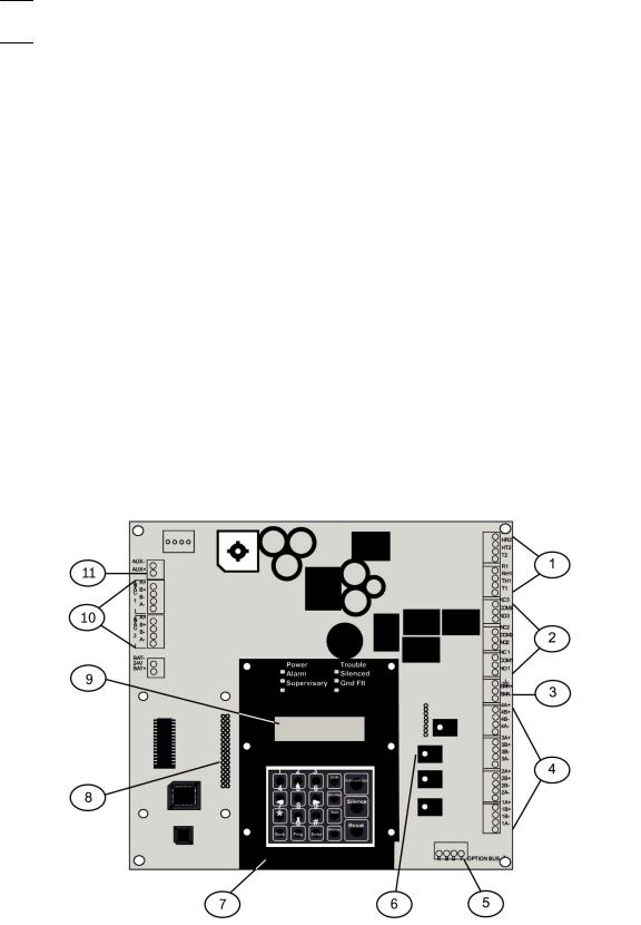
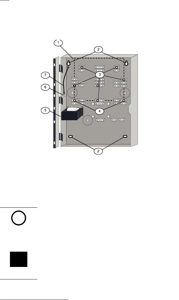
For the location of the major items on the FPD 7024 Control Board, see the following figure: |
|
Figure 2.1: FPD-7024 ControlBoard
|
1 |
TELCO terminal strip |
7 |
Keypad |
|
|
|
|
|
|
2 |
Relay terminal strip |
8 |
D7039 MUX expansion module |
|
|
|
|
connector pins |
|
|
|
|
|
|
3 |
Smoke power terminal strip |
9 |
LCD display |
|
|
|
|
|
|
|
|
|
|
2012.08 | 04 | F01U008458 |
Installation and Operation Manual |
Bosch Security System, Inc. |

Fire Alarm Control Panels Overview | en 9
4 |
Zone input terminal strip |
10 |
NAC terminal strip |
|
|
|
|
5 |
Option bus terminal strip |
11 |
Auxiliary power terminal strip |
|
|
|
|
6 |
FPC-7034 point expander connector |
|
|
|
pins |
|
|
|
|
|
|
2.2 |
Components |
2.2.1 |
On-board conventional points |
|
All on-board points and points implemented with the FPC-7034 work with twoor four-wire |
detectors. The system has an optional alarm verification feature.
Number of two-wire circuits |
Four circuits, expandable to eight using an |
|
FPC-7034 Expander |
|
|
Type of Circuit |
Class B, Style B and Class A, Style D as |
|
needed) |
|
|
EOL Resistor |
2.21 kΩ (P/N: 25899 or F01U034504), UL |
|
listed |
|
|
Supervisory Existing |
8 mA to 20 mA |
|
|
Required Existing for Alarm |
25 mA |
|
|
Maximum Short Circuit Existing |
45 mA |
|
|
Maximum Line Resistance |
150 Ω |
|
|
Circuit Voltage Range |
20.4 VDC to 28.2 VDC |
|
|
Maximum Detectors per Point |
20 detectors (two-wire) |
|
|
Total Detector Standby Existing |
3 mA maximum |
|
|
Response Time1 |
Either fast (500 ms) or programmable (from |
|
1 second to 89 seconds) |
|
|
Dirty Detector Monitoring |
Implements Bosch Security Systems, Inc. |
|
Chamber Check and GE Interlogix, Inc. |
|
CleanMe protocol to monitor conventional |
|
loops for dirty detectors. |
|
|
1 See , 24 |
|
Table 2.1: Two-wire circuits |
|
All on-board points, and points activated with the FPC 7034 Four Point Expander, are continuously monitored for detectors signaling a dirty condition using the Bosch Security Systems, Inc. Chamber Check and GE Interlogix, Inc. CleanMe protocols. To prevent nuisance reports, a two-minute delay occurs before a dirty detector is annunciated. A six-minute delay occurs after the detector restores from the dirty condition before the control panel restores the condition.
2.2.2 Off-board addressable points (with D7039 Multiplex Expansion Module)
The D7039 Multiplex Expansion Module adds:
– Two Class B, Style 4 or one Class A, Style 6 Signaling Line Circuits (SLCs)
Bosch Security System, Inc. |
Installation and Operation Manual |
2012.08 | 04 | F01U008458 |

10 en | Overview |
Fire Alarm Control Panels |
|
|
–Each point is individually supervised for proper connection to the common bus (when over ten points are troubled, up to ten troubles are shown per bus and the balance of the troubles is indicated by a common bus failure message).
–Response time can be set to fast, or programmed from 1 to 89 seconds.
–Input points on the SLCs are implemented with a D7042 Eight Input Remote Module.
2.2.3 |
Enclosure Housing |
|
The standard enclosure is 18 ga., cold-rolled steel, and measures 20.75 in. x 15 in. x 4.25 in. |
|
(52.7 cm x 38.1 cm x 10.8 cm). A keyed lock is included, and the LEDs and LCD display are |
|
visible through the door. |
2.2.4 |
Remote LCD Keypads |
|
|
||
|
Maximum number of keypads: Four FMR 7033 LCD Fire Keypads. |
||||
|
For wiring Requirements, see Option bus wiring requirements, 34 |
||||
2.2.5 |
Remote LED Annunciators |
|
|
||
|
Maximum number of annunciators: Eight D7030 eight-zone LED Annunciators. |
||||
|
For wiring Requirements, see Option bus wiring requirements, 34 |
||||
2.2.6 |
D7032 - use with the D7030X |
|
|
||
|
When a D7032 Eight-Zone LED Annunciator Expander is connected to the D7030X, eight |
||||
|
additional LED zones appear. This allows the D7030X/D7032 combination to show 16 LED |
||||
|
zones. Up to eight D7030X/D7032 combinations can be connected to the FPD 7024 Fire Alarm |
||||
|
Control Panel. |
|
|
|
|
|
|
|
|
|
|
|
Notice! |
|
|
|
|
|
Each D7030X processes 16 zones of information. If no D7032 is attached, only the lower eight |
||||
|
zones are shown. |
|
|
|
|
|
|
|
|
|
|
|
|
|
|
|
|
|
Notice! |
|
|
|
|
|
The column labeled “shown on D7030X” in the LED assignments table below applies regard- |
||||
|
less if an attachment of a D7032 to any D7030X is made. |
|
|||
|
|
|
|
|
|
|
For LED assignments when up to eight D7030X/D7032 combinations are used, see the |
||||
|
following table: |
|
|
|
|
|
|
|
|
|
|
|
D7030X |
zones |
shown on |
shown on |
comments |
|
|
covered |
D7030X |
D7032 (if |
|
|
|
|
|
attached) |
|
|
|
|
|
|
|
|
1 |
1 to 16 |
1 to 8 |
9 to 16 |
Combination with lowest option |
|
|
|
|
|
bus address (such as Address 1) |
|
|
|
|
|
|
|
2 |
17 to 32 |
17 to 24 |
25 to 32 |
Combination with second lowest |
|
|
|
|
|
option bus address (such as |
|
|
|
|
|
Address 2) |
|
|
|
|
|
|
|
3 |
33 to 48 |
33 to 40 |
41 to 48 |
Combination with third lowest |
|
|
|
|
|
option bus address (such as |
|
|
|
|
|
Address 3) |
|
|
|
|
|
|
2012.08 | 04 | F01U008458 |
Installation and Operation Manual |
Bosch Security System, Inc. |
Fire Alarm Control Panels Overview | en 11
D7030X |
zones |
shown on |
shown on |
comments |
|
covered |
D7030X |
D7032 (if |
|
|
|
|
attached) |
|
|
|
|
|
|
4 |
49 to 64 |
49 to 56 |
57 to 64 |
Combination with fourth lowest |
|
|
|
|
option bus address (such as |
|
|
|
|
Address 4) |
|
|
|
|
|
5 |
1 to 16 |
1 to 8 |
9 to 16 |
Fifth combination repeats first |
|
|
|
|
combination |
|
|
|
|
|
6 |
17 to 32 |
17 to 24 |
25 to 32 |
Sixth combination repeats second |
|
|
|
|
combination |
|
|
|
|
|
7 |
33 to 48 |
33 to 40 |
41 to 48 |
Seventh combination repeats third |
|
|
|
|
combination |
|
|
|
|
|
8 |
49 to 64 |
49 to 56 |
57 to 64 |
Eighth combination repeats fourth |
|
|
|
|
combination |
|
|
|
|
|
Table 2.2: LED assignments for LED Annunciators |
|
|||
For the LED display for Zones 49 to 64, see the following table.
LED |
Zone |
Description |
|
|
|
1 |
49 |
User defined |
|
|
|
2 |
50 |
User defined |
|
|
|
3 |
(reserved) |
|
|
|
|
4 |
52 |
General fire alarm monitor waterflow (non-silencable) |
|
|
|
5 |
53 |
General fire alarm monitor (silencable) |
|
|
|
6 |
(reserved) |
|
|
|
|
7 |
55 |
General Supervisory (silencable) |
|
|
|
8 |
56 |
General Waterflow (silencable) |
|
|
|
9 |
(reserved) |
|
|
|
|
10 |
58 |
General supervisory alarm (non-silencable) |
|
|
|
11 |
(reserved) |
|
|
|
|
12 |
(reserved) |
|
|
|
|
13 |
61 |
General waterflow alarm (non-silencable) |
|
|
|
14 |
(reserved) |
|
|
|
|
15 |
63 |
General alarm monitor waterflow (non-silencable) |
|
|
|
16 |
(reserved) |
|
|
|
|
Table 2.3: LED display for Zones 49 to 64
See also
–D7032 - use with the D7030X, 10
Bosch Security System, Inc. |
Installation and Operation Manual |
2012.08 | 04 | F01U008458 |

12 en | Overview |
Fire Alarm Control Panels |
|
|
2.2.7 Communicator
The communicator can report to two phone numbers or IP addresses with full single, double, and back-up reporting. Communicates in SIA, Modem IIIa2, Contact ID, BFSK, and 3/1 and 4/2 Tone burst formats (available communication formats depend on phone or IP connection).
Notice!
The communicator must be enabled and configured to operate. The communicator and phone line monitors are disabled in the default factory configuration.
Phone Line and Phone Number/IP Selection: To ensure the delivery of critical reports, the fire panel has two phone lines and two phone numbers or IP addresses that can be used for reporting. Reports can be directed to one or both of two phone numbers or IP addresses using the Report Steering feature in the control panel programming. Note that Account Number 1 is used with Phone Number/IP 1, and Account Number 2 is used with Phone Number/IP 2. Except for test reports, the control panel automatically selects the phone line or IP address to use. If the report is not successful after two attempts on Line 1, the control panel automatically switches and uses Phone Line 2. One exception is when test reports (manual or automatic) are sent. Test reports are sent every 4 hours to 28 days. Each time a test report is sent, the control panel alternates phone lines. This happens even if the monitor says the line is bad. If the user sends two manual test reports, both phone lines can be tested. The first report uses one line, and the second uses the other line. During normal operation, the automatic test uses a different line each day. Because the control panel automatically selects which line to use, both phone lines must use the same dialing sequences for sending reports. For example, a line that requires a 9 to be dialed for an outside line cannot be paired with a line that does not require a 9.
For more information on report steering, see Report Steering, 83.
Notice!
PBX lines and ground start lines do not comply with NFPA requirements for digital communication.
While the control panel is idle, the FACP monitors the primary and alternate telephone lines by monitoring the line for trouble. The FACP monitors each line every 12 seconds. When a trouble still exists after three samples (36 seconds), the FACP sends a trouble report and activates the yellow trouble LED and trouble relay.
Danger!
If the central station receives the automatic test report only every other day, this indicates that one phone line at the protected premises is inoperative.
Correct this condition immediately, because other critical reports can be delayed when the communicator is trying to send the test signal through the inoperative phone line (once each 48 hours).
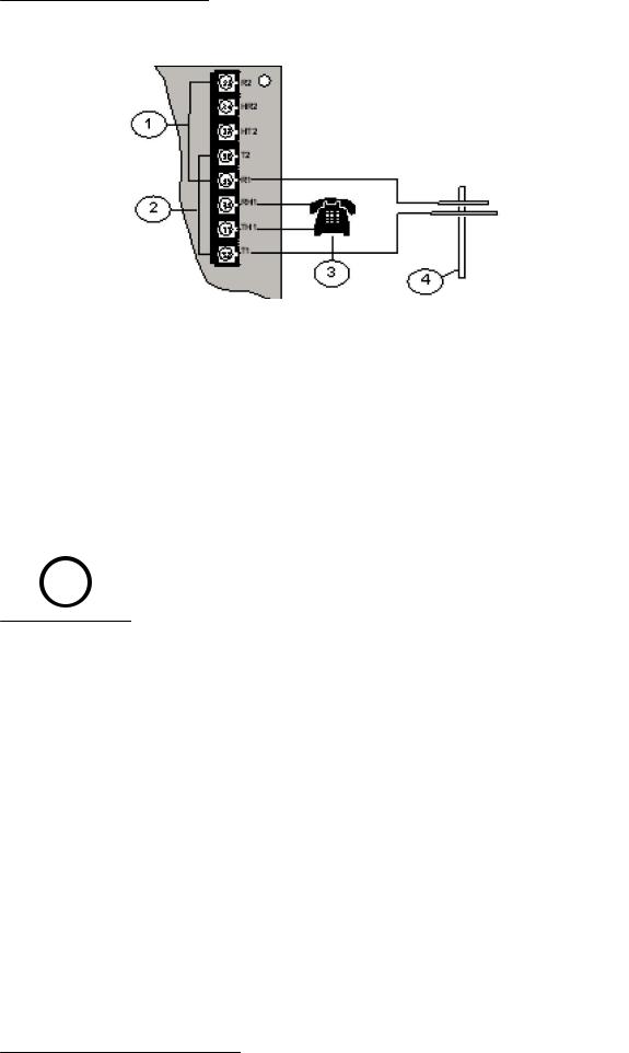
Supplemental Reporting: While two independent phone lines are required for UL864 Central Station service, the FACP can be configured with one phone line if the control panel is used only for supplemental reporting on a local, remote station or auxiliary system.
To install the control panel with only one phone line, connect a jumper from T1 to T2 and a jumper from R1 to R2. These jumper connections are shown in the following figure:
2012.08 | 04 | F01U008458 |
Installation and Operation Manual |
Bosch Security System, Inc. |
Fire Alarm Control Panels |
Overview | en 13 |
|
|
Figure 2.2: Supplemental Reporting
1 |
Jumper from R1 to R2 |
3 |
House phone |
|
|
|
|
2 |
Jumper from T1 to T2 |
4 |
TELCO line |
|
|
|
|
2.2.8 Users
The system allows up to 16 individual users, or up to 100 users when the D7039 is installed. A personal identification number (PIN, the four-digit code entered at the keypads) and an authority level to determine which functions can be performed can be assigned to each user. For PINs, see Personal identification numbers (PINs), 47.
2.2.9 |
Lightning protection |
|
|
Notice!
This system is intended for installation entirely within one building.
Metal-oxide varistors (MOVs) and spark gaps provide protection from lightning surges and static discharges.
2.2.10Battery backup calculation
To calculate the standby battery capacity required by NFPA when using the FPD 7024, see the two following tables:
Device |
Quantity |
Standby |
Total |
Alarm existing/ |
Total alarm |
|
|
existing/device |
standby |
device |
|
|
|
|
|
|
|
FPD 7024 |
1 |
200 mA |
200 mA |
380 mA |
380 mA |
Control Panel |
|
|
|
|
|
|
|
|
|
|
|
FPC 7034 |
|
44 mA |
|
156 mA |
|
Four Point |
|
|
|
|
|
Expander |
|
|
|
|
|
|
|
|
|
|
|
D7035/B Octal |
|
8 mA + 30 mA 2 |
|
8 mA + 30 mA 2 |
|
Relay1 |
|
|
|
|
|
D7048/B Octal |
|
10 mA |
|
10 mA |
|
Driver Module |
|
|
|
|
|
|
|
|
|
|
|
Bosch Security System, Inc. |
Installation and Operation Manual |
2012.08 | 04 | F01U008458 |

14 en | Overview Fire Alarm Control Panels
Device |
Quantity |
Standby |
Total |
Alarm existing/ |
Total alarm |
|
|
existing/device |
standby |
device |
|
|
|
|
|
|
|
FMR 7036 |
|
80 mA |
|
100 mA |
|
Annunciator |
|
|
|
|
|
Keypad |
|
|
|
|
|
|
|
|
|
|
|
D7030X |
|
27 mA |
|
132 mA |
|
Eight Point LED |
|
|
|
|
|
Annunciator1 |
|
|
|
|
|
D7030X S2 |
|
35 mA |
|
175 mA |
|
Eight Point LED |
|
|
|
|
|
Annunciator |
|
|
|
|
|
|
|
|
|
|
|
D7030X S8 |
|
35 mA |
|
175 mA |
|
Eight-Point LED |
|
|
|
|
|
Annunciator |
|
|
|
|
|
|
|
|
|
|
|
D7032 Eight |
|
1 mA |
|
90 mA |
|
Point LED |
|
|
|
|
|
Annunciator |
|
|
|
|
|
Expander |
|
|
|
|
|
|
|
|
|
|
|
FMR 7033 |
|
80 mA |
|
100 mA |
|
Keypad1 |
|
|
|
|
|
D7039 MUX |
|
150 mA |
|
150 mA |
|
Expansion |
|
|
|
|
|
Module |
|
|
|
|
|
|
|
|
|
|
|
D7042/B |
|
18 mA |
|
18 mA |
|
Addressable |
|
|
|
|
|
Eight Point Input |
|
|
|
|
|
|
|
|
|
|
|
D7050 MUX |
|
0.50 mA |
|
0.56 mA |
|
Photoelectric |
|
|
|
|
|
Smoke Detector |
|
|
|
|
|
|
|
|
|
|
|
D7050TH MUX |
|
0.50 mA |
|
0.56 mA |
|
Photoelectric |
|
|
|
|
|
Smoke Detector |
|
|
|
|
|
|
|
|
|
|
|
FMM-7045 MUX |
|
0.55 mA |
|
0.55 mA |
|
Pull Station |
|
|
|
|
|
|
|
|
|
|
|
D7044 MUX |
|
0.55 mA |
|
0.55 mA |
|
Single Input Fire |
|
|
|
|
|
|
|
|
|
|
|
D7044M MUX |
|
0.55 mA |
|
0.55 mA |
|
Mini Contact |
|
|
|
|
|
Module |
|
|
|
|
|
|
|
|
|
|
|
D7052 MUX Dual |
|
0.55 mA |
|
0.55 mA |
|
Input Fire |
|
|
|
|
|
|
|
|
|
|
|
2012.08 | 04 | F01U008458 |
Installation and Operation Manual |
Bosch Security System, Inc. |

Fire Alarm Control Panels Overview | en 15
Device |
Quantity |
Standby |
|
Total |
Alarm existing/ |
Total alarm |
|
|
existing/device |
|
standby |
device |
|
|
|
|
|
|
|
|
D7053 MUX I/ O |
|
0.70 mA |
|
|
0.70 mA |
|
Module Fire |
|
|
|
|
|
|
|
|
|
|
|
|
|
Smoke Detectors |
|
|
|
|
|
|
|
|
|
|
|
|
|
Bells, Horns, and |
|
|
|
|
|
|
so on |
|
|
|
|
|
|
|
|
|
|
|
|
|
Other Sensors |
|
|
|
|
|
|
|
|
|
|
|
|
|
Other |
|
|
|
|
|
|
|
|
|
|
|
|
|
|
|
Grand Total |
|
Grand Total |
||
|
|
Standby Existing |
|
Alarm Existing |
||
|
|
|
|
|
|
|
1 The 24 VDC existing requirements for the D7030X, FMR-7033 and D7035 are shown at 75% of the 12 VDC level shown on the specification sheets for these models. The FPD-7024 regulates 24 VDC power from the battery to 12 VDC for these accessories.
2 Add 30 mA for each relay activated
Table 2.4: Standby battery capacity calculations
The units shown in the following table are Amp hours (Ah), and the calculations include a 20% derating factor.
Grand Total Standby Existing (in amps) |
CS |
|
|
Total Hours of Standby Required |
HS |
(usually 24 or 60): |
|
|
|
Total Standby Capacity (multiply CS x HS) |
TS= CS x HS |
|
|
|
|
Grand Total Alarm Existing (in amps) |
CA |
|
|
Total Hours of Alarm Time Required |
HA |
(usually 0.083 o 0.25): |
|
|
|
Total Standby Capacity (multiply CA x HA) |
TA= CA x HA |
|
|
|
|
Total Capacity Required (add TA + TS): |
TC = TA + TS |
|
|
|
|
Required Capacity with 20% Derating |
C = TC x 1.2 |
(TC x 1.2) |
|
|
|
Table 2.5: Required battery size calculation |
|
Notice!
The required battery size to support the system can be calculated using the tables for Standby load battery size, 16 and Alarm load battery size, 16.
Bosch Security System, Inc. |
Installation and Operation Manual |
2012.08 | 04 | F01U008458 |

16 en | Overview |
Fire Alarm Control Panels |
|
|
2.2.11Required batteries for existing load
Use the following procedure to determine the battery requirements for your system:
–Estimate the size of the battery required to support the standby load using the following table:
Standby load battery |
Capacityr required |
Capacity required for |
Capacity required for |
size chart |
for 24 hours |
48 hours |
60 hours |
|
|
|
|
Grand Total Standby |
|
|
|
Existing |
|
|
|
|
|
|
|
100 to 200 mA |
5.8 |
11.5 |
14.4 |
|
|
|
|
201 to 300 mA |
8.6 |
17.3 |
21.6 |
|
|
|
|
301 to 400 mA |
11.5 |
23.0 |
28.8 |
|
|
|
|
401 to 500 mA |
14.4 |
28.8 |
36.0 |
|
|
|
|
501 to 600 mA |
17.3 |
34.6 |
X |
|
|
|
|
601 to 700 mA |
20.2 |
X |
X |
|
|
|
|
701 to 800 mA |
23.0 |
X |
X |
|
|
|
|
801 to 900 mA |
25.9 |
X |
X |
|
|
|
|
901 to 1000 mA |
28.8 |
X |
X |
|
|
|
|
1001 to 1100 mA |
31.7 |
X |
X |
|
|
|
|
Table 2.6: Standby load battery size (Ah)
–Estimate the size of the battery required to support the alarm load using the following table:
Alarm load |
Capacity |
Capacity |
Capacity |
Capacity |
Capacity |
battery size |
required for |
required for |
required for |
required for |
required for |
chart |
5 minutes |
10 minutes |
15 minutes |
30 minutes |
45 minutes |
|
|
|
|
|
|
Grand Total |
|
|
|
|
|
Alarm Existing |
|
|
|
|
|
|
|
|
|
|
|
250 to |
0.1 |
0.1 |
0.2 |
0.3 |
0.5 |
500 mA |
|
|
|
|
|
|
|
|
|
|
|
501 to |
0.1 |
0.2 |
0.3 |
0.6 |
0.9 |
999 mA |
|
|
|
|
|
|
|
|
|
|
|
1.0 to 1.5 A |
0.2 |
0.3 |
0.5 |
0.9 |
1.4 |
|
|
|
|
|
|
1.6 to 2.0 A |
0.2 |
0.4 |
0.6 |
1.2 |
1.8 |
|
|
|
|
|
|
2.1 to 2.5 A |
0.3 |
0.5 |
0.8 |
1.5 |
2.3 |
|
|
|
|
|
|
2.6 to 3.0 A |
0.3 |
0.6 |
0.9 |
1.8 |
2.7 |
|
|
|
|
|
|
3.1 to 3.5 A |
0.4 |
0.7 |
1.1 |
2.1 |
3.2 |
|
|
|
|
|
|
3.6 to 4.0 A |
0.4 |
0.8 |
1.2 |
2.4 |
3.6 |
|
|
|
|
|
|
Table 2.7: Alarm load battery size (Ah)
–Add the results together for the total battery size.
2012.08 | 04 | F01U008458 |
Installation and Operation Manual |
Bosch Security System, Inc. |

Fire Alarm Control Panels |
Overview | en 17 |
|
|
–Select the next larger standard battery for the system.
If the results show a requirement for a battery over 40 Ah, reduce the existing load or add an external regulated fire protective signaling power supply.
2.2.12 |
Compatible devices |
|
|
|
|
|
Device |
Function |
|
|
|
|
D7030 Eight Point LED |
Identifies the location of a fire alarm for up to eight zones |
|
Annunciator |
allowed per system. |
|
|
|
|
D7030X Eight Point LED |
Identifies the location of a fire alarm for up to eight zones |
|
Annunciator |
allowed per system. |
|
|
|
|
D7030X S2 Eight Point LED |
An eight zone LED annunciator, of which two zones are |
|
Annunciator |
reserved for supervisory functions. It has Power and |
|
|
Trouble LEDs plus eight zone LEDs that can be labeled |
|
|
individually. |
|
|
|
|
D7030X S8 Eight Point LED |
An eight-zone LED annunciator, of which all eight zones are |
|
Annunciator |
reserved for supervisory functions. It has Power and |
|
|
Trouble LEDs plus eight-zone LEDs that can be labeled |
|
|
individually. |
|
|
|
|
D7032 Eight Point LED |
Attaches to a D7030X and identifies the location of a fire |
|
Annunciator Expander |
alarm for eight additional zones. |
|
|
|
|
FMR 7033 Alphanumeric LCD |
The FMR 7033 LCD Keypad combines remote annunciator |
|
Keypad |
and controller functions for the FPD 7024. Up to four |
|
|
keypads can be connected. |
|
|
|
|
FPC 7034 Four Point Expander |
Allows the FPD 7024 Control Panel to support four |
|
|
additional loops. The FPC 7034 plugs into the control panel |
|
|
and provides four Class B, Style 4 loops that are identical |
|
|
in characteristics to the loops on the control panel. One |
|
|
FPC 7034 is allowed per system. |
|
|
|
|
D7035/B Octal Relay Module |
Provides eight Form C relay outputs for addition to the |
|
|
system. The outputs are programmable and can be |
|
|
activated by system events. Each output operates |
|
|
independently of the other seven outputs for complete |
|
|
flexibility. The D7035 connects to the option bus; up to |
|
|
two are allowed per system. The D7035B comes installed |
|
|
on a mounting skirt. |
|
|
For required enclosure modification, see also the D7035 |
|
|
Installation Guide. |
|
|
|
|
FMR 7036 Fire Annunciator |
Establishes the location of a fire alarm. |
|
Keypad |
|
|
|
|
|
FPP RNAC 8A 4C Remote NAC |
Adds four NFPA 72 Class B, Style Y Notification Appliance |
|
Power Supply |
Circuits through the option bus and is supervised by the |
|
|
control panel. The FPP RNAC 8A 4C connects to the option |
|
|
bus of the FPD 7024 control panel and up to four are |
|
|
allowed per system. |
|
|
|
Bosch Security System, Inc. |
Installation and Operation Manual |
2012.08 | 04 | F01U008458 |

18 en | Overview Fire Alarm Control Panels
|
Device |
Function |
|
|
|
|
D7039 Multiplex Expansion |
Provides either 2 two-wire (Class B, Style 4) multiplex |
|
Module |
buses or 1 four-wire (Class A, Style 6) multiplex bus. In |
|
|
Class A mode, up to 120 addressable points can be added. |
|
|
In Class B Mode, up to 247 addressable points can be |
|
|
added. The D7039 connects directly to the control panel. |
|
|
One is allowed per system. |
|
|
|
|
D7042/B Eight Input Remote |
Provides eight Class B, Style 4 input points. Connect up to |
|
Module |
15 modules to MUX Bus A, and 15 on MUX Bus B. The |
|
|
D7042 is powered by 12 VDC supplied by the option bus |
|
|
power terminals, in addition to the two wire data |
|
|
connection. The D7042 can not be used on a signal line |
|
|
circuit (SLC) configured for Class A, Style 6 operation. |
|
|
|
|
D7048/B Octal Driver Module |
Provides eight open collector transistor outputs for |
|
|
addition to the FPD 7024 Fire Alarm Control panels. It |
|
|
connects to the control panels through the option bus. |
|
|
|
|
FMM-7045 MUX Pull Station |
UL Listed fire alarm initiating device. |
|
|
|
|
D7044 MUX Single Input |
Connects a normally open contact device to the multiplex |
|
Module |
bus of the FPD 7024 with a supervised local loop. The |
|
|
D7044 draws operating power from the FPD 7024. |
|
|
|
|
D7044M MUX Mini Contact |
Connects a contact device to the multiplex bus of the |
|
Module |
FPD 7024 with a supervised input loop. The D7044 draws |
|
|
operating power from the FPD 7024. |
|
|
|
|
D7052 MUX Dual Input Fire |
Connects to the multiplex bus of the FPD 7024 and |
|
|
provides two supervised input zones for connecting |
|
|
conventional normally-open inputs. The D7052 draws |
|
|
operating power from the FPD 7024. |
|
|
|
|
D7053 MUX I/O Module Fire |
Connects to the multiplex bus of the FPD 7024 and |
|
|
implements a supervised local loop, and a Form C relay |
|
|
output. Up to 20 modules can be connected to each MUX |
|
|
bus. The D7053 draws operating power from the |
|
|
FPD 7024. |
|
|
|
|
D7050/TH MUX Smoke Detector |
The D7050/TH is a photo-electric smoke detector with a |
|
|
heat option. It connects to the multiplex bus of the |
|
|
FPD 7024. The D7050 draws operating power from the |
|
|
FPD 7024. |
|
|
|
|
DX4020 / B420 models |
The Conettix DX4020 and B420 models are communication |
|
|
devices that manages secure, two-way IP communications |
|
|
over Ethernet networks. |
|
|
|
|
ITS DX4020 G |
The ITS-DX4020-G enables two-way IP or dialed |
|
|
communications over a commercial GPRS/GSM network. |
|
|
Typical applications are event reporting to a central |
|
|
monitoring station and remote access to Bosch control |
|
|
panels. |
|
|
|
|
|
|
2012.08 | 04 | F01U008458 |
Installation and Operation Manual |
Bosch Security System, Inc. |

Fire Alarm Control Panels |
Overview | en |
19 |
|
|
|
Table 2.8: Compatible devices |
|
|
|
Install D7042 modules only at addresses: |
|
|
|
|
|||
|
|
|
|
|
|
|
|
|
|
9 |
17 |
25 |
33 |
41 |
49 |
57 |
65 |
|
|
|
|
|
|
|
|
|
|
73 |
81 |
89 |
97 |
105 |
113 |
121 |
129 |
|
|
|
|
|
|
|
|
|
|
137 |
145 |
153 |
161 |
169 |
177 |
185 |
193 |
|
|
|
|
|
|
|
|
|
|
201 |
209 |
217 |
225 |
233 |
241 |
|
|
|
|
|
|
|
|
|
|
|
|
Do not install D7052 and D7053 modules at these addresses: |
|
|
|||||
|
|
|
|
|
|
|
|
|
|
16 |
24 |
32 |
40 |
48 |
56 |
64 |
72 |
|
|
|
|
|
|
|
|
|
|
80 |
88 |
96 |
104 |
112 |
120 |
128 |
136 |
|
|
|
|
|
|
|
|
|
|
144 |
152 |
160 |
168 |
176 |
184 |
192 |
200 |
|
|
|
|
|
|
|
|
|
|
208 |
216 |
224 |
232 |
240 |
248 |
255 |
|
|
|
|
|
|
|
|
|
|
|
Table 2.9: Address restrictions for the D7042, D7052, and D7053 |
|
|
|
||||
2.3 |
Parts List |
|
|
|
|
|
|
|
The FPD 7024 comes with:
–One FPD-7024 Control/Communicator in static-resistant bag
–One enclosure with transformer
–One hardware pack containing the hardware necessary for installing the control panel in the enclosure
–One enclosure lock, washer, and keys
–Six end-of-line (EOL) resistors
Bosch Security System, Inc. |
Installation and Operation Manual |
2012.08 | 04 | F01U008458 |
20 en | Fire Safety Fire Alarm Control Panels
3 |
|
Fire Safety |
|
|
|
|
|
Danger! |
|
|
|
|
|
No fire detection device or system is 100% foolproof. |
|
|
|
|
|
|
|
|
This fire alarm system can provide early warning of a developing fire. Such a system, however, |
|
|
does not ensure protection against property damage or loss of life resulting from a fire. Any |
|
|
fire alarm system can fail to warn for any number of reasons (such as smoke not reaching a |
|
|
detector that is behind a closed door). |
|
|
|
|
|
Notice! |
|
|
This system must be regularly tested (when installed, when modified, and at least annually |
|
|
thereafter) to ensure continued performance. |
|
|
|
|
|
When considering detectors for residential applications, refer to NFPA Standard 72, The |
|
|
National Fire Alarm Code. This standard is available at a nominal cost from: The National Fire |
|
|
Protection Association, Batterymarch Park, Quincy, MA 02269. |
3.1 |
|
Smoke detector layout |
3.1.1 |
General considerations |
|
|
|
Proper location of detection devices is one of the most critical factors in a fire alarm system. |
|
|
Smoke detectors should not be installed in dead air spaces or close to ventilating or air |
|
|
conditioning outlets because smoke can be circulated away from the detector. Locations near |
|
|
air inlets are favored. |
|
|
Avoid areas subject to normal smoke concentrations such as kitchens, garages, or near |
|
|
fireplaces. |
|
|
Do not install smoke detectors where normal area temperatures are above +100°F (+38°C) or |
|
|
below +32°F (0°C). |
|
|
Avoid areas of high humidity and dust concentrations. |
|
|
Place the edge of ceiling mounted detectors no closer than 4 in. (10 cm) from any wall. |
|
|
Place the top edge of wall-mounted detectors between 4 in. and 12 in. (10 cm and 30 cm) |
|
|
from the ceiling. |
|
|
For exact mounting information, refer to the instructions provided with the smoke detectors. |
3.1.2 |
Family residences |
|
|
|
Providing a Fire Warning System: Most fire deaths occur in the home, especially during |
|
|
sleeping hours. The minimum level of protection requires smoke detectors to be installed |
|
|
outside of each separate sleeping area and on each additional story of the dwelling. |
Notice!
For added early warning protection, install detectors in all separate areas including the basement, bedrooms, dining room, utility room, furnace room, and hallways.
For residential smoke detector locations, see the following figure:
2012.08 | 04 | F01U008458 |
Installation and Operation Manual |
Bosch Security System, Inc. |
Fire Alarm Control Panels |
Fire Safety | en 21 |
|
|
Figure 3.1: Smoke detector locations in residential settings |
|
|
||
|
|
|
|
|
|
1 |
Bedroom |
5 |
Basement |
|
|
|
|
|
|
2 |
Hall |
6 |
Recreation room |
|
|
|
|
|
|
3 |
Living room |
7 |
Kitchen |
|
|
|
|
|
|
4 |
Dining room |
* |
Smoke detector |
|
|
|
|
|
3.2 |
Having and practicing an escape plan |
|||
A fire warning can be wasted unless the personnel planned in advance for a rapid and safe exit from the building.
Draw a floor plan of the entire building showing two exits from each sleeping area and two from the building. Since stairwells and hallways can be blocked during a fire, provide exits from sleeping area windows. Make copies of the plan and practice it with all personnel.
Arrange a meeting place outside and away from the building. Once out of the building, all occupants should immediately go to the pre-selected location to be accounted for.
Provide a barricade between personnel and fire, smoke, and toxic gases (such as closing all sleeping area doors before retiring).
Instruct children on opening their bedroom windows and exiting safely from the building. If exiting is not possible, teach them to stay at the open window and shout for help until it arrives.
If a fire alarm occurs after retiring, wake the children by shouting to them from behind your closed door. Tell them to keep their bedroom doors closed.
If the top of your bedroom door is uncomfortably hot, do not open it. There is most likely fire, intolerable heat, or smoke on the other side. Shout to all family members to keep their bedroom doors closed and to exit the building by alternate routes.
If the top of the door is not uncomfortably hot, brace the bottom of the door with your foot, and the top with one hand, then open the door about one inch. Be prepared to slam the door shut if there is any pressure against the door or if any hot air rushes in.
If there is no evidence of excessive heat or pressure, leave the room and close the door behind you. Shout appropriate instructions to all family members and immediately leave the building by the planned routes. If heavy smoke is present, drop to your hands and knees, or crawl to remain below the smoke level.
Bosch Security System, Inc. |
Installation and Operation Manual |
2012.08 | 04 | F01U008458 |

22 en | Installation Fire Alarm Control Panels
4 |
Installation |
4.1 |
Installation guide for UL Listed systems |
4.1.1 |
FPD 7024 UL Listings |
|
The FPD 7024 is UL Listed for the following: |
|
– Commercial Fire Alarm (UL Standard UL864) |
|
– Type Service: Auxiliary, Local, Central Station, and Remote Station |
|
– Type Initiating: Automatic, Manual, Sprinkler Supervisory, and Waterflow |
|
Install the control panel according to NFPA 72 for Commercial Fire installations. |
4.1.2 |
Installation considerations |
|
Failure to install and program the control panel according to the requirements in this section |
|
voids the listing mark of Underwriters Laboratories. |
|
– The standby battery capacity is 40 Ah at 24 VDC. |
|
– The total nominal existing must not exceed 1.25 A in standby or 4 A when in alarm. |
|
– The control panel must be mounted indoors and within the protected area. |
|
– Grounding must be according to article 250 of the NEC (NFPA 70). |
|
– Points must be connected to UL Listed, compatible devices. |
|
– The ground wire provided with the enclosure must be connected between the door and |
|
the enclosure using the supplied nuts. |
|
– Do not program the ground start feature. |
|
– Select Phone Monitoring if the digital alarm communicator transmitter (DACT) feature is |
|
used. |
4.1.3 |
UL requirements |
|
|
|
Notice! |
|
The system must be tested after installation and after any re-programming, including pro- |
|
gramming performed by downloading. |
When used in UL Listed installations, the control panel must conform to certain programming requirements. For a list of the required program entries specific UL Listed installations, see the Programming features for UL864 table, 49.
Commercial Fire Alarm (Central Station [DACT] and Local) Required Accessories
– At least one Bosch Security Systems, Inc. Model F220 P Smoke Detector with an F220 Family Base; or another UL Listed compatible smoke detector.
– At least one Horn Strobe or Bell (provides 85 dB for UL985 and NFPA 72 requirements; other UL Listed compatible devices listed for regulated 24 V can be used) is required for this application and must be installed inside the protected area.
– Four-wire detectors must be used with UL Listed power supervision devices. A compatible UL Listed four-wire detector is the Bosch Security Systems, Inc. F220 P in an F220 B6 Family Base. A compatible UL Listed relay is the Bosch Security Systems, Inc. D275.
– All points must be used with the resistor provided.
Report Programming
– Program non-supervisory and supervisory reports for those points used.
– Program trouble reports.
– Set AC Failure Report Delay for a delay of 1 hour to 3 hours.
– Set automatic test report frequency to occur at least every 24 hours.
2012.08 | 04 | F01U008458 |
Installation and Operation Manual |
Bosch Security System, Inc. |

Fire Alarm Control Panels |
Installation | en 23 |
|
|
Timer Programming
–Program Auto Silence Time for not less than five minutes, or to “0” to disable auto-silence
operation.
Point Programming
–For fire points: open = trouble, latching.
Alarm Output Programming
–Program notification appliance circuits to activate from the appropriate input points.
Communications Programming
–If used for Central Station Service, select a communication format compatible with the central station. Enable monitoring of both phone lines.
UL Listed Accessory Devices
D132B Multi-use Reversing Relay Module
The D132B is a multi-purpose, fully configurable, smoke power-reversing module for activating detectors with local annunciation. The D132B operates both two-wire and four-wire circuits and also works with Class A or Class B initiating circuits. An alarm latch connection is provided to allow an initiating loop to be held in alarm after the detector loop power is reversed to activate any sounders. The D132B does not affect compatibility between the FACP and detectors, or the FACP and Notification Appliance Circuits (NACs).
See also the D132B Installation Guide for detailed installation instructions for the D132B module. One of the installation options shown in the D132B Installation Guide is also shown in the following figure:
Bosch Security System, Inc. |
Installation and Operation Manual |
2012.08 | 04 | F01U008458 |

24 en | Installation |
Fire Alarm Control Panels |
|
|
Figure 4.1: Wiring the D132B smoke power reversing module
1 |
Power limited and supervised |
7 |
12/24 VDC |
|
|
|
|
2 |
Optional alarm latch |
8 |
24 V reversing detectors |
|
|
|
|
3 |
Loop |
9 |
2.2 kΩ EOL (power limited and |
|
|
|
supervised) |
|
|
|
|
4 |
Class A |
10 |
Not used |
|
|
|
|
5 |
Latch |
11 |
24 V NACs |
|
|
|
|
6 |
NAC |
|
|
|
|
|
|
D185 Reverse Polarity Module
The D185 Reverse Polarity Module is a UL Listed module that connects the control panel with either a single set or a pair of leased telephone company (TELCO) lines in NFPA 72 remote station applications. It relays system alarm status information from the control panel to a monitoring station. The D185 operates with either 12 VDC or 24 VDC supply.
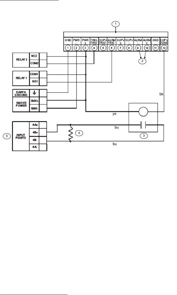
For typical wiring of the D185 module, see the following figure:
2012.08 | 04 | F01U008458 |
Installation and Operation Manual |
Bosch Security System, Inc. |
Fire Alarm Control Panels |
Installation | en 25 |
|
|
Figure 4.2: Wiring the D185
1 |
D185 module |
5 |
Fire control panel |
|
|
|
|
2 |
To monitoring station |
bk |
black |
|
|
|
|
3 |
D275 |
bu |
blue |
|
|
|
|
4 |
2.2 kΩ EOL |
ye |
yellow |
|
|
|
|
The module can signal alarm, trouble, and supervisory conditions. The Wiring the D185 figure, 24 shows the module being used to signal alarm and trouble conditions only. With a third relay (available from the eight-relay expansion module) and an additional leased line, supervisory conditions can also be signaled.
In the example in the Wiring the D185 figure, Relay 1 must be programmed to operate on Alarm (Zone 63) and Relay 2 must be programmed to operate on Trouble (Zone 62). Program Input 4 to operate as a Supervisory point. Any alarm causes the voltage to the monitoring station to be interrupted. Placing the D185 in test mode causes a SUPERVISORY TROUBLE. See also the D185 Installation Manual.
4.2 |
Installing the enclosure |
|
|
To install the enclosure, follow these instructions: |
|
|
1. |
Using the enclosure as a template, mark the top mounting holes on the mounting surface. |
|
2. |
Start the mounting screws (not supplied) for these two holes. |
|
3. |
Slide the enclosure onto these screws so that the screws rest on the thinner section of |
|
|
the holes. |
|
4. |
Tighten the screws. |
Bosch Security System, Inc. |
Installation and Operation Manual |
2012.08 | 04 | F01U008458 |
26 en | Installation |
Fire Alarm Control Panels |
|
|
5.Install and tighten the remaining two screws in the bottom mounting holes.
6.Knock out the desired wire entrances on the enclosure.
For mounting hole locations, see the following figure:
Figure 4.3: Enclosure iInstallation |
|
|
||
|
|
|
|
|
|
1 |
Control panel location |
5 |
Transformer |
|
|
|
|
|
|
2 |
Mounting holes |
6 |
Stud |
|
|
|
|
|
|
3 |
Retainer holes for standoffs |
7 |
Ground wire |
|
|
|
|
|
|
4 |
Retainer holes for support posts |
|
|
|
|
|
|
|
|
Notice! |
|
If using the knockouts located at the bottom of the enclosure, install batteries in a separate |
|
enclosure. |
|
|
4.3 |
Installing the FPD 7024 |
|
|
|
Danger! |
|
The control circuit board in the FPD-7024 is static sensitive. |
|
To avoid damage to sensitive components, touch ground before handling the control board. |
|
This discharges any static electricity in your body. For example, run the ground wire to the en- |
closure before handling the control circuit board. Continue touching the enclosure while installing the control board.
2012.08 | 04 | F01U008458 |
Installation and Operation Manual |
Bosch Security System, Inc. |
Fire Alarm Control Panels |
Installation | en 27 |
|
|
|
|
Warning!
Before the circuit board is installed, connect the supplied ground wires between the door and
!the enclosure and from the transformer to the enclosure using the supplied nuts. Both grounds connect to the stud in the enclosure to the left of the circuit board.
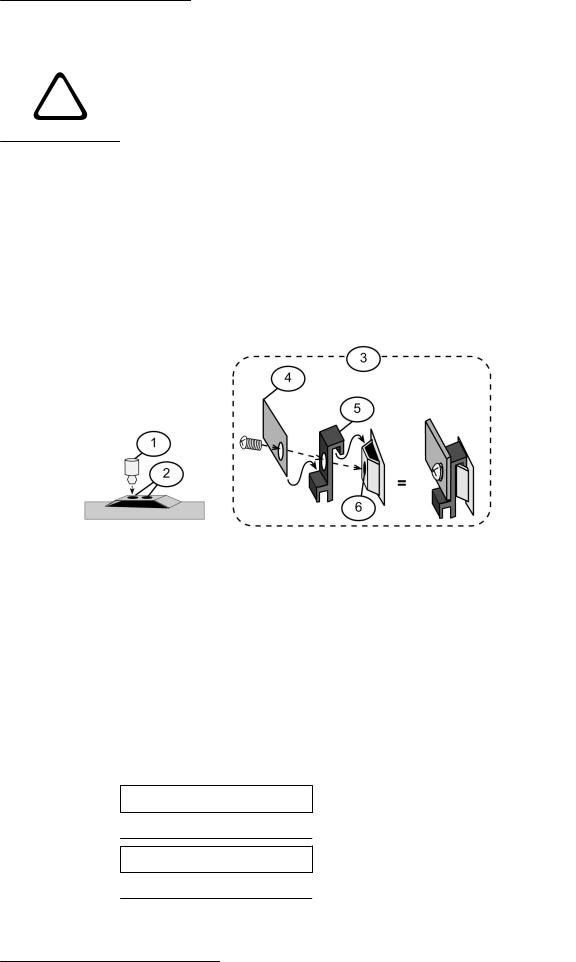
For installation illustrations, see the figures for Enclosue installation, 26 and for Standoff and support post installation, 27.
1.Insert the three support posts in the enclosure’s retainer holes.
2.Press the 1/8 in. nylon standoffs (P/N: F01U034705) into the retainer holes.
3.Slide the top of the control panel onto the retainer tabs (the slots under the top of the frame). When the control panel is in the retainer tabs, it rests on the posts.
4.Secure the bottom of the circuit board by inserting and tightening the screws at the two bottom corners through the support posts and the retainer holes.
For installing standoffs and support posts, see the following figure:
Figure 4.4: Standoff and support post installation |
|
|
||
|
|
|
|
|
|
1 |
1/8 in. nylon standoff |
4 |
Corner of circuit board |
|
|
|
|
|
|
2 |
Retainer holes |
5 |
Support post |
|
|
|
|
|
|
3 |
Support post assembly |
6 |
Retainer hole in enclosure |
|
|
|
|
|
4.4 |
Installing optional equipment |
|
|
|
Two expansion options connect directly to the control panel, and are automatically detected and supervised when the control panel is powered:
–FPC-7034 Four Point Expander
–D7039 Multiplex Expansion Module
When the control panel is powered after installing one of these options, the control panel displays one of the following windows:
4Z EXP DETECTED
PRESS BACK KEY
MUX DETECTED
PRESS BACK KEY
Press the [*/BACK] key to confirm the installation of the device and automatically set it up for supervision.
Bosch Security System, Inc. |
Installation and Operation Manual |
2012.08 | 04 | F01U008458 |

28 en | Installation |
Fire Alarm Control Panels |
|
|
If the [*/BACK] key is not pressed during the power-up time-out period, the control panel resumes operation using the last confirmed status of the affected expander and displays an installation error condition.
Warning!
Expansion devices such as point expanders and multiplex expanders are disabled if they are
!removed from the control panel configuration after installation. You cannot disable supervision of these devices when they are installed.
For additional information, see the installation instructions for the specific expanders.
Notice!
EEPROM fault at first installation
When the D7039 Multiplex Expansion Module is first installed, the system displays an EEPROM fault. Execute the default procedure to synchronize the EEPROM on the expansion module to the EEPROM in the control panel. Remove power to the control panel, then reapply power and re-install option bus devices after the default procedure.
Notice!
Loss of programming
Replacing a D7039 Multiplex Expansion Module causes the loss of programming of expansion points and PINs. Reprogram all multiplex point and PINs if you replace the D7039.
When the D7039 is first installed, or anytime the control panel is powered with a D7039 that has no points programmed, the system automatically starts the multiplex auto-programming process:
AUTO PROGRAM?
_______:YES(1) NO(0)
Pressing the [1] key starts auto-programming, and pressing [0/Prog] allows the control panel to continue normal startup. The menu automatically closes with NO selected if no key is pressed after several minutes.
For detailed instructions on the auto-programming mode, see Auto Program, 93.
2012.08 | 04 | F01U008458 |
Installation and Operation Manual |
Bosch Security System, Inc. |
Fire Alarm Control Panels Connection | en 29
5 |
Connection |
5.1 |
FACP terminal connection |
|
|
Danger!
Incorrect connections may result in damage to the unit and personal injury.
Warning!
!Before servicing this equipment, remove all power including the transformer, battery and phone lines.
Notice!
Shared cable is not recommended for option bus, telephone or NAC wiring.
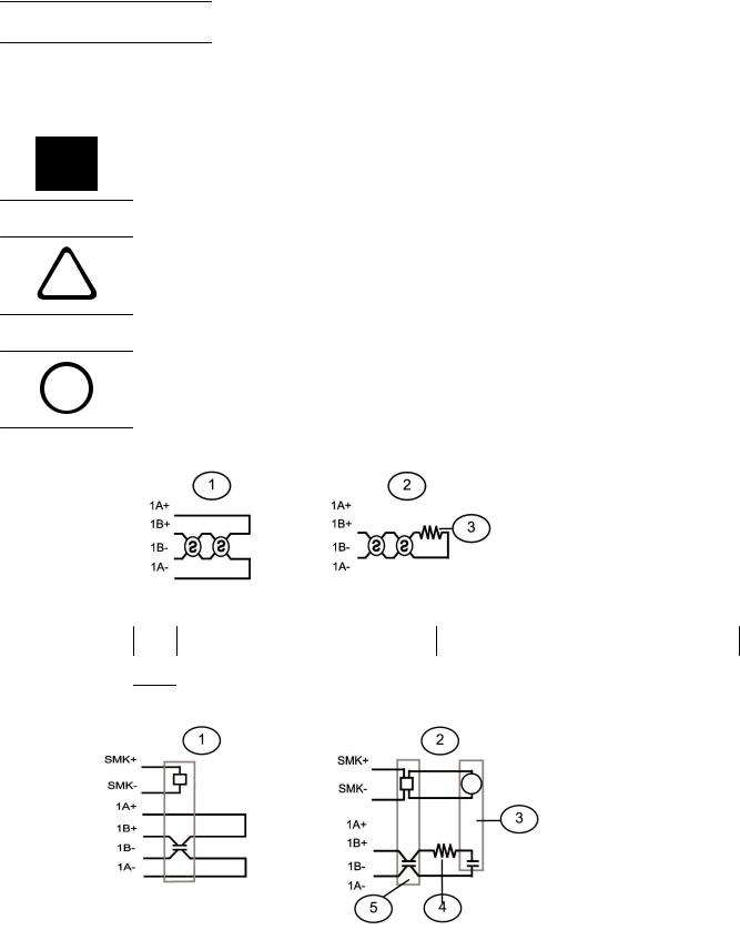
Figure 5.1: Typical 2-wire smoke detector wirin (supervised)g
1 Class A, Style D |
3 |
EOL resistor |
|
|
|
2 Class B, Style B
Figure 5.2: Typical 4-wire smoke detector wiring
|
1 |
Class A, Style D |
4 |
EOL resistor |
|
|
|
|
|
|
2 |
Class B, Style B |
5 |
Smoke detector |
|
|
|
|
|
|
3 |
EOL relay |
|
|
|
|
|
|
|
|
|
|
|
|
Bosch Security System, Inc. |
Installation and Operation Manual |
2012.08 | 04 | F01U008458 |
30 en | Connection |
Fire Alarm Control Panels |
|
|
Notice!
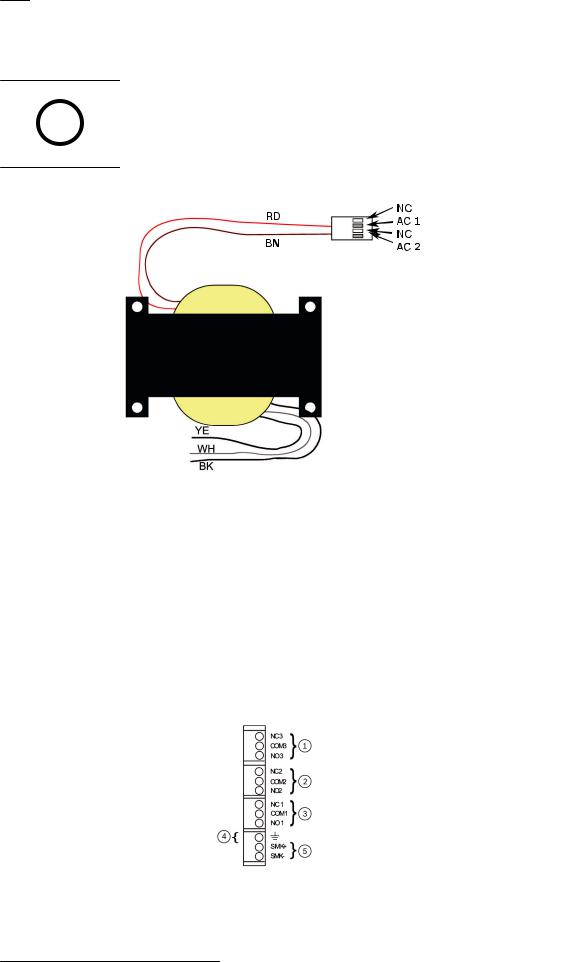
All wiring except battery terminal and primary AC power is power-limited. Primary AC and battery wires must be separated from other wires by at least ¼ in. (64 mm) and tied to prevent movement.
Figure 5.3: Transformer
RD |
red |
|
|
BN |
brown |
|
|
supervised: |
|
|
|
YE |
yellow |
|
|
WH |
white |
|
|
BK |
black |
|
|
Figure 5.4: Input Points
2012.08 | 04 | F01U008458 |
Installation and Operation Manual |
Bosch Security System, Inc. |
Loading...