


F220 Series Detectors with
F220-B6/C/E/R Bases
Installation Manual
|
|
|
|
|
|
|
|
en |
English manual |
|
|

2 en | Legal |
F220 Series Detectors with F220-B6/C/E/R Bases |
|
|
1 Legal
1.1Trademarks
CleanMe® is a registered trademark of GE Interlogix in the United States and/or other countries.
Chamber Check® is a registered trademark of Bosch Security Systems, Inc. in the United States.
Chambermaid™ is a trademark of Bosch Security Systems, Inc. in the United States.
ENVI-RO-TECH™ is a trademark of Tech Spray L.P.
TECHSPRAY® is a registered trademark of Tech Spray L.P.
1.2Required Maintenance and Testing
Keep the detector calibrated for proper operation. NFPA 72, The National Fire Alarm Code, recommends performing calibration tests at installation, then every other year. Depending on local regulations, calibration testing might be required more than once a year.
Perform functional testing yearly.
NOTE! Notify all concerned parties before any
i maintenance or testing of the fire alarm system and upon completion of these activities.
Test the calibration (to meet NFPA 72) using either the magnet test or measuring the calibration with a calibrated product from No Climb Products Ltd. Quickly determine the calibration by a visual inspection of the detector’s LED (refer to Section 4.4 Flash Rate and Trouble Indication on page 22). These tests confirm whether or not the detector is within its factory marked calibration range.
At least once a year vacuum or wipe the external part of the detector clean. Pay particular attention to the detector screens in areas of heavy insect activity or dust. To clean the chamber,
4998138694 -04 | 2007.01 |
Installation Manual |
Bosch Security Systems, Inc. |

F220 Series Detectors with F220-B6/C/E/R Bases |
General Information | en 3 |
||
|
|
||
|
use a can of clean, dry compressed air (such as TECHSPRAY |
||
|
ENVI-RO-TECH Duster) which is available at office and alarm |
||
|
supply stores. Shorten the plastic tube that comes with the |
||
|
compressed air to about 2 in. (5 cm). Place the tube or needle |
||
|
valve through the Chambermaid valve in the bottom of the |
||
|
detector (refer to Figure 2.2 on page 7). |
||
|
|
||
i |
NOTE! Do not paint the detectors. Paint or other foreign |
||
matter covering the detector can prevent smoke |
|||
detection. |
|
||
|
|
|
|
2 |
General Information |
|
|
|
This document covers mounting, wiring, power requirements, |
||
|
testing, and maintenance for the F220-B6, F220-B6C, F220-B6E, |
||
|
and F220-B6R Detector Bases and the F220 Series Heat and |
||
|
Photoelectric Smoke Detectors. Install them according to |
||
|
NFPA 72. |
|
|
|
|
||
i |
NOTE! For proper system installation, read and |
||
understand NFPA-72 before installation. |
|||
|
|||
|
|
||
|
For installation guidelines, refer to Installation Considerations |
||
|
for Smoke and Fire Detectors (P/N: 26715). |
||
2.1F220-B6 Series Detector Bases
2.1.1Compatible Control Panels
Two-wire:
NOTE! Bosch Security Systems, Inc. makes no claim written, oral, or implied that the F220 Series Detectors
i work with any two-wire control panels except those specified in the Base Compatibility chart in Technical Service Note (P/N: 4998148185).
Bosch Security Systems, Inc. |
Installation Manual |
4998138694 -04 | 2007.01 |

4 en | General Information |
F220 Series Detectors with F220-B6/C/E/R Bases |
|
|
Four-wire: Compatible with all UL Listed four-wire control panels. Refer to the control panel manufacturer’s installation instructions for proper end-of-line (EOL) resistor selection.
2.1.2Base Comparisons
The F220-B6 is a two-wire base, while the F220-B6C, F220-B6E, and F220-B6R are four-wire bases. All three of the four-wire bases have a Form A alarm relay. In addition to the alarm relay, the:
–F220-B6C has a Form C auxiliary alarm relay
–F220-B6E has a power supervision (EOL) relay
NOTE! Use the F220-B6RS when a built-in sounder is needed. The F220-B6RS also has a Form A alarm relay. Refer to the F220 Series Detectors with the F220-B6RS
i Installation Manual (P/N: F01U029847).
For addressable systems, use the F220-B6PM Addressable POPIT Master Base or F220-B6PS Addressable POPIT Base. Refer to the F220-B6PS/M Installation Manual (P/N: 4998149982).
4998138694 -04 | 2007.01 |
Installation Manual |
Bosch Security Systems, Inc. |

F220 Series Detectors with F220-B6/C/E/R Bases |
General Information | en 5 |
|
|
2.1.3Base Features
|
|
12 |
|
|
|
10 |
|
11 |
|
|
|
|
|
|
|
11 |
|
9 |
|
|
|
|
|
|
|
13 |
|
|
|
|
12 |
|
7 |
8 |
|
|
|
||
|
6 |
|
3 |
12 |
|
4 |
|
|
|
|
|
2 |
|
|
|
5 |
|
|
|
|
|
1 |
11 |
|
|
|
|
||
|
|
|
|
|
|
11 |
|
|
|
|
12 |
|
|
|
1. |
Terminal 1 |
8. |
Remote Terminal (c) |
|
2. |
Terminal 2 |
9. |
Tamper Tab (Locking Bar) |
|
3. |
Terminal 3 |
10. |
Tamper Tab (Locking Bar |
|
4. |
Terminal 4 |
|
Mount) |
|
5. |
Terminal 5 |
11. |
Alignment Key (4 places) |
|
6. |
Resettable Auxiliary Power |
12. |
Snap Lock (4 places) |
|
|
Positive (+) In and Out |
13. |
Earth Shield Terminal |
|
|
Terminals (b1 and b2) |
|
(optional) |
|
7. |
Resettable Auxiliary Power |
|
|
|
|
Negative (-) In and Out |
|
|
|
|
Terminal (a1/a2) |
|
|
|
Fig. 2.1 Base Features
Bosch Security Systems, Inc. |
Installation Manual |
4998138694 -04 | 2007.01 |

6 en | General Information |
F220 Series Detectors with F220-B6/C/E/R Bases |
|
|
2.2F220 Series Detectors
2.2.1About F220 Series Detector Heads
The F220 Series Detector Heads listed inTable 2.1 each require an F220-B6 Series Base.
WARNING! The F220-PTHC detects carbon monoxide
!(CO) as a component of a fire. Do not use the F220-PTHC as a stand-alone CO detector.
F220-135 |
Electronic heat detector 135°F (57°C), fixed |
|
temperature and rate-of-rise |
||
|
||
|
|
|
F220-135F |
Electronic heat detector 135°F (57°C), fixed |
|
|
temperature only |
|
|
|
|
F220-190F |
Electronic heat detector 190°F (88°C), fixed |
|
temperature only |
||
|
|
|
F220-P |
Photoelectric smoke detector |
|
|
|
|
F220-PTH |
Photoelectric smoke detector with integral 135°F |
|
(57°C) heat sensor |
||
|
||
|
|
|
|
Photoelectric smoke detector with integral 135°F |
|
F220-PTHC |
(57°C) heat sensor and CO enhanced smoke |
|
|
detection |
|
|
|
Table 2.1 F220 Series Detector Heads
4998138694 -04 | 2007.01 |
Installation Manual |
Bosch Security Systems, Inc. |
F220 Series Detectors with F220-B6/C/E/R Bases |
General Information | en 7 |
|
|
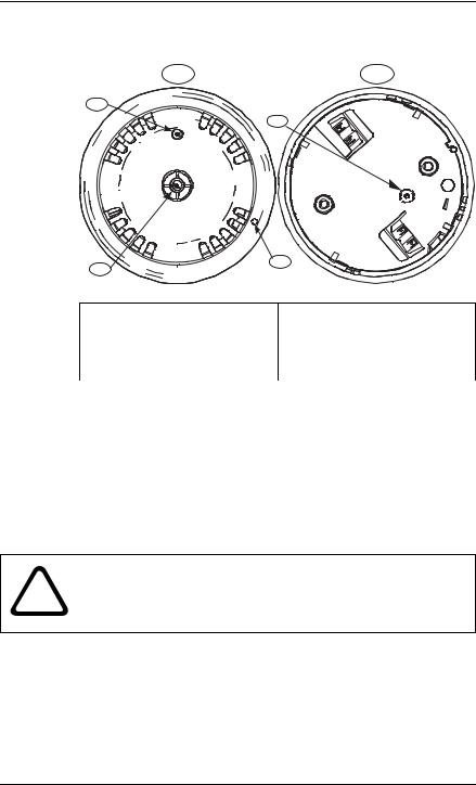
2.2.2F220 Series Detector Features
1 |
5 |
2 |
|
|
6 |
4
3
1. Front of detector |
4. Unlocking port |
2.Light-emitting diode (LED) 5. Back of detector
3. Thermistor |
6. Chambermaid location |
(heat detectors only) |
|
|
|
Fig. 2.2 Detector Features |
|
2.2.3F220 Series Heat Detector Heads
The F220 Heat Detector Heads can be identified by color coding (refer to Table 2.2).
F220-135 |
No circle around the thermistor |
|
|
F220-135F |
A gray circle around the thermistor |
|
|
F220-190F |
A black circle around the thermistor |
|
|
Table 2.2 Distinguishing Heat Detectors
WARNING! The F220-135, F220-135F and F220-190F are
!not life safety devices. Use them with F220-B6 Series bases to provide general property protection.
Bosch Security Systems, Inc. |
Installation Manual |
4998138694 -04 | 2007.01 |

8 en | General Information |
F220 Series Detectors with F220-B6/C/E/R Bases |
|
|
2.2.4F220 Series Smoke Detector Heads
The F220 Series Smoke Detector Heads are UL Listed, openarea photoelectric smoke detectors that work with commercial fire protective signaling systems and household fire warning systems. Select the appropriate mounting base to configure the detectors for two-wire or four-wire versions (refer to
Section 2.1.2 Base Comparisons on page 4).
To verify power to the detector and a functioning smoke sampling circuitry, a dual color LED indicator flashes green every eight seconds when operating normally. It flashes once every four seconds when a trouble condition exists. If the detector determines an alarm condition exists, the LED changes from flashing green to steady red. The detector returns to normal when power is interrupted and the alarm condition clears.
Throughout its normal life cycle, the smoke detector monitors and periodically adjusts itself to keep the sensitivity at its factory calibrated level. When excessively dirty, the detector’s LED flash rate changes from an eight second flash rate to a four second rate. If CleanMe is selected, the detector sends a CleanMe signal to the compatible control panel to indicate a dirty smoke detector.
Refer to Section 4.3 Set CleanMe Feature on page 22.
2.3Technical Specifications
2.3.1General Specifications
Air Velocity |
4000 ft/min (1200 m/min) maximum |
|
|
Operating |
+32°F to 100°F (0°C to 38°C) |
Temperature |
|
|
|
Relative |
0% to 95% (non-condensing) |
Humidity |
|
|
|
Table 2.3 Specifications - Detectors and Bases
4998138694 -04 | 2007.01 |
Installation Manual |
Bosch Security Systems, Inc. |

F220 Series Detectors with F220-B6/C/E/R Bases General Information | en 9
2.3.2 |
Base Specifications |
|
|
|
|
|
Alarm Current (only base current, detector current excluded) |
|
|
|
|
|
F220-B6: |
Two-wire base; no base current |
|
|
|
|
F220-B6C: |
31 mA at 12 VDC |
|
|
35 mA at 24 VDC |
|
|
40 mA maximum at 30 VDC |
|
|
|
|
F220-B6E: |
25 mA at 12 VDC |
|
|
30 mA at 24 VDC |
|
|
34 mA maximum at 30 VDC |
|
|
|
|
F220-B6R: |
13.5 mA at 12 VDC |
|
|
16.5 mA at 24 VDC |
|
|
19 mA maximum at 30 VDC |
|
|
|
|
Standby Current |
|
|
|
|
|
F220-B6/C/R: |
No current draw in standby |
|
|
|
|
F220-B6E: |
16 mA maximum at 30 VDC |
|
|
|
|
Voltage |
|
|
|
|
|
F220-B6 (two-wire): |
8.5 VDC to 32.0 VDC |
|
|
|
|
F220-B6C/E/R (four-wire): |
10.0 VDC to 30.0 VDC |
|
|
|
|
Table 2.4 F220-B6 Series Base Specifications |
|
2.3.3Detector Specifications
Current
Alarm: |
20 mA minimum at 8.5 VDC |
|
35 mA maximum at 32 VDC |
|
|
Standby: |
0.12 mA maximum |
|
|
Startup: |
0.12 mA maximum |
|
|
Powerup Time |
22 second maximum |
|
|
Rate of Rise |
|
|
|
F220-135: |
15°F/min (9°C/min) or greater |
|
|
Voltage |
|
|
|
Operating: |
8.5 VDC to 32.0 VDC |
|
|
RMS Ripple: |
25% of DC input |
|
|
Table 2.5 F220 Series Detector Heads Specifications
2.4Electrical Supervision
When the F220-B6 Series Bases are wired according to the instructions in this document, the control panel initiates a trouble signal when a detector is removed from its base,
Bosch Security Systems, Inc. |
Installation Manual |
4998138694 -04 | 2007.01 |
 Loading...