


Bosch Remote Control for
GWH-635-ES/ESO/250SX/250SXO/2400E/2400EO
6 720 606 990 (07.01) JS

Contents
Contents
1Declaration of conformity FCC 3
2 |
Remote control data |
4 |
|
|
|
3 |
Parts supplied |
4 |
|
|
|
4 |
Using the remote control |
4 |
4.1 |
Description of the LCD |
4 |
4.2Remote control transceiver PCB
|
installation |
5 |
4.3 |
Remote control activation |
7 |
4.3.1 |
AF board |
7 |
4.3.2 |
SU board |
8 |
4.4Hot water temperature adjustment
by remote control |
9 |
4.5"Program" button on the remote
|
control |
9 |
4.6 |
"Priority" function |
10 |
4.7 |
Error messages |
11 |
|
|
|
5 |
Troubleshooting |
12 |
5.1 |
Replacing batteries |
12 |
5.2 |
Cleaning |
12 |
5.3 |
Troubleshooting |
12 |
|
|
|
6 |
Notes |
15 |
2 |
6 720 606 990 |
Safety instructions
Safety instructions
BRead the following instructions very carefully to ensure correct operation.
B Follow safety instructions.
Caution: Any changes or modifications not expressly approved by the party responsible for compliance could void the user’s authority to operate the equipment.
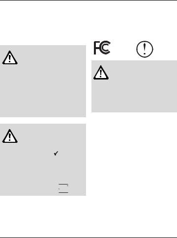
1Declaration of conformity FCC
This device meets the requirements of FCC Directives.
Caution: The remote control can be used only in the following countries: United States of America and Canada.
Caution: the remote control is waterproof and can also be used in the shower  . Nevertheless, you should ensure it is not immersed in water, for instance in the bathtub
  .
.
This device complies with Part 15 of the FCC rules. Operation is subject to the following two conditions: (1) This device may not cause harmful interference, and (2) this device must accept any interference received, including interference that may cause undesired operation.
6 720 606 990 |
3 |
Remote control data
2Remote control data
Remote control for temperature adjustment of Bosch water heaters GWH- 635-ES/ESO/250 SX/250SXO/ 2400E/2400EO.
Technical Data:
Battery power |
Alkaline AA LR 6 |
|
supply |
2 x 1.5V |
|
Frequency |
915 MHz |
|
Type of |
IP X6 |
|
protection |
||
|
||
User range |
98 ft (30 m) |
|
|
|
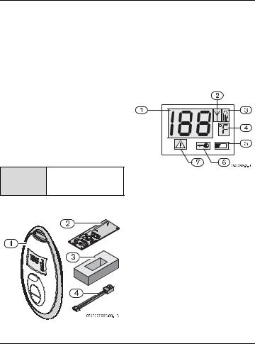
1Remote control
2 Remote control transceiver PCB
3Support block
4PCB connection cable
4Using the remote con-
trol
4.1Description of the LCD
Further Indications:
Remote |
Up to 6 remote controls |
Fig. 2 |
Multifunctional LCD |
|
||||
control |
can be programmed |
for |
|
|||||
|
|
|
|
|
||||
|
|
one single appliance.. |
|
1 |
Displays temperature, error codes |
|||
|
|
|
|
|
and functions |
|
|
|
3 |
Parts supplied |
|
2 |
"Remote |
control |
in operation" |
||
|
|
|
|
|
indication (signal arriving at remote |
|||
|
|
|
|
|
control) |
|
|
|
|
|
|
|
3 |
Device in operation (with burner |
|||
|
|
|
|
|
on) |
|
|
|
|
|
|
|
4 |
Temperature measurement |
unit |
||
|
|
|
|
|
(possible in °C and °F) |
|
||
|
|
|
|
5 |
Remote |
control |
battery |
level |
|
|
|
|
|
indication |
(weak |
signal coming |
|
|
|
|
|
|
from the remote control) |
|
||
|
|
|
|
6 |
Priority |
function |
(temperature |
|
|
|
|
|
|
cannot be modified by other user |
|||
|
|
|
|
|
when water is running) |
|
||
|
|
|
|
7 |
"Error code" symbol |
|
||
Fig. 1 |
|
Parts |
|
|
|
|
|
|
4 |
6 720 606 990 |
Using the remote control
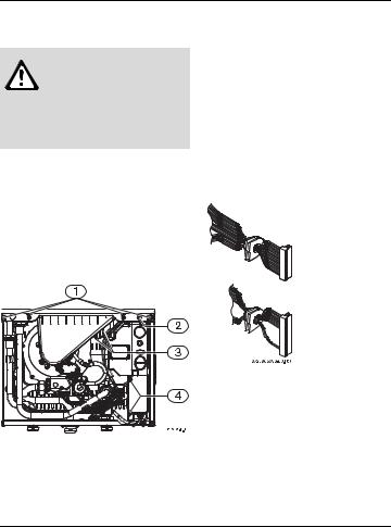
4.2Remote control transceiver PCB installation
Warning: For safety reasons, disconnect the power supply to the water heater before performing installation.
Pre-installation preparation
B Disconnect power supply to heater.
B Remove plastic decals on front panel.
B Loosen two Philips head screws located behind plastic decals.
B Lift front cover upward and remove.
2) being careful not to damage the foam sealant material on it.
BRemove control unit auxiliary cover (Fig. 3, pos. 4).
B Remove the two electrical strip connectors inside the auxiliary cover (Fig. see diagram below) and then loosen the 110V power supply cord retaining nut located underneath the heater. Once loosened, the power cord can be pulled up through the heater to provide sufficient slack.
Once auxiliary cover is off, pull off the two electrical strip connectors from the board. Once off, the wiring harness can be removed from the case by pulling their rubber seals outward.
Fig. 3
B Remove the 5 screws on the front retaining bar (see Fig. 3, pos. 1 and
Fig. 4 Electrical strip connectors
BAt the ignition electrodes, pull off the 2 yellow igniter wires that come from the top of the control board (Fig. 3, pos. 3). Then pull the complete control board forward and out of the heater, pull up the power supply cord further if more slack is needed.
6 720 606 990 |
5 |
 Loading...