


OPERATING INSTRUCTIONS

OPERATING INSTRUCTIONS |
|
DiBos |
|
|
|
|
4.998.137.631 A1 |
|
|
|
|
|
|
|
|
|
|
|
|
|
|
|
|
|
Contents |
|
|
|
|
|
|
|
||
|
|
|
||
Introduction and safety instructions . . . . . . . . . . . . . . . . . . . 3 |
Looking at, printing, saving, swapping out, |
|
||
Introduction to the system |
4 |
and deleting archive images |
17 |
|
Deleting archives / searching for archive |
|
|||
Password |
4 |
|
||
images and additional data |
18 |
|||
Logging on |
4 |
|||
|
|
|||
Changing users/logging off |
4 |
Connecting backup drive and / swapping |
|
|
Exiting the system / ending the program |
4 |
out archive images on diskette |
19 |
|
The basic live image window |
5 |
Formatting a CD |
20 |
|
|
|
|||
General information |
6 |
Swapping out data on CD |
22 |
|
Basic window menu bar |
7 |
Alarm simulation |
23 |
|
Basic window toolbar / alarm simulation bar |
8 |
|||
|
|
|||
Basic window status bar / connection window |
9 |
Connection with a remote station |
24 |
|
|
|
|||
Controlling a dome camera |
10 |
Searching for and looking at archive |
26 |
|
|
|
images from the remote station |
||
The basic image archive window |
12 |
Notes |
27 |
|
Image archive menu bar |
13 |
|||
|
|
|||
Image archive toolbar |
14 |
|
|
|
Image archive toolbar / alarm simulation bar |
15 |
|
|
|
Image archive status bar / connection window |
16 |
|
|
|
Recorder buttons |
|
|
|
|
BOSCH Security Systems GmbH |
– 2 – |
A1 02.03 |
Introduction and safety instructions
What do these operating instructions tell you?
These operating instructions provide you with all relevant information that you need in order to perform the tasks described in the table of contents quickly and easily.
You will find more detailed information about the respective screens online on your system if you press the F1 key or click the Help button.
Caution!
To avoid electrical shock, do not remove the cover. Leave all maintenance to qualified personnel.
Warning!
To avoid fire or electrical shock, never expose the device to rain or humidity.
Warning!
Installation should only be undertaken by qualified customer service personnel in accordance with all applicable electrical regulations.
Power connection!
Devices with or without power cords have voltage in the device as soon as the power cord is plugged into the outlet. However, the device is only ready for use if the power switch (ON/OFF) is on ON. If you unplug the power cable from the outlet, the voltage supply to the device is completely halted.
Note
It your are not able to accomplish some of the described steps of this manual, it may be that you don’t have the rigth authority level. In this case please contact your authorized dealer.
Notes on cleaning
When cleaning the surface, be sure that you do not use any caustic or scrubbing cleansers and that no liquid gets inside the device.
The device may only be operated by trained
persons! For security reasons and in order to avoid faulty operation, any authorization code required for operation should only be communicated to these persons.
Service station:
Telephone:
BOSCH Security Systems GmbH |
– 3 – |
A1 02.03 |
Introduction to the system
When the computer is booted, the system runs automatically in the background and is able to respond to signals and record images. You must only log on if you wish to perform operating tasks. Only authorized users have access to operate the system, based on a password. Depending on your access privileges, with the user interface you can:
·view live images for monitoring purposes and manually switch camera views ·open the image archive and retrieve, print, and delete saved images ·perform system configuration
·perform an alarm simulation
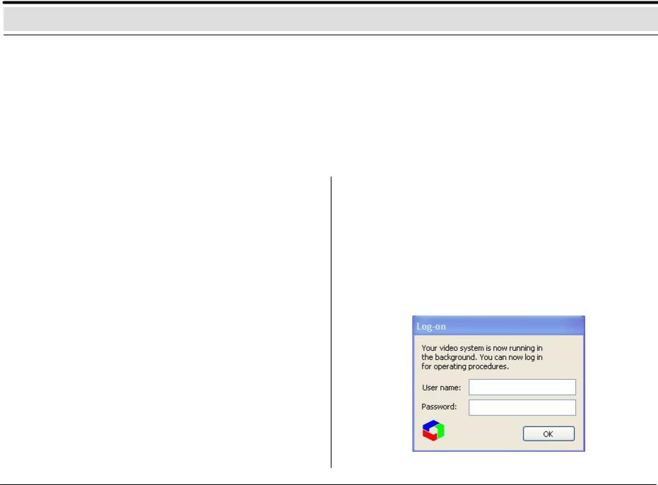
You must log on to the system in order to commence operation.
After you have switched on the system and the live image screen appears, you will see a dialog box in the middle of the screen that invites you to log on.
Password |
|
Exiting the system / ending the program |
For the password, there are no restrictions as to the type and number |
|
Select System from the menu bar and click Exit system. |
of characters permitted. |
|
|
You can change the password on the System menu. |
|
|
|
|
|
Logging on |
|
|
Enter your user name and password and confirm with OK. You are |
|
Logon screen |
|
||
now on the live image. |
|
|
The live image consists of the live image basic window, which is also |
|
|
displayed if no video station was selected or one or several |
|
|
connection windows |
|
|
|
|
|
Changing users/logging off |
|
|
On the System menu, you can change users or log off. During a |
|
|
change of user, the system continues to run in the background. This |
|
|
is recommended if you leave the system. |
|
|
BOSCH Security Systems GmbH |
– 4 – |
A1 02.03 |

The basic live image window
General information
1 4
5
2
6
7
3
The basic live image window
1Menu bar
2Toolbar
3Status bar
Connection window
4Title bar of the connection window for the selected station
5Display all configured cameras of the selected station
6Display of selected camera images
7Display of status of all configured alarm inputs of the selected station and re lay statuses
Display of several live images
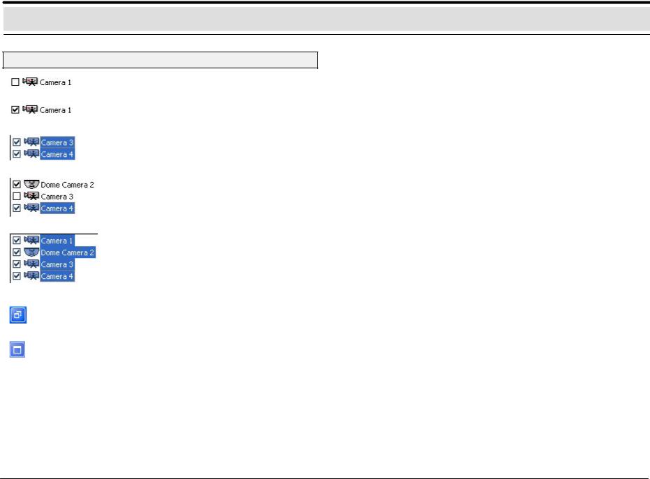
You can display several live images, depending on the number of connected and configured cameras. The live images are always arranged automatically from left to right in consecutive rows.
For each camera marked with a  , a live image is shown.
BOSCH Security Systems GmbH |
– 5 – |
A1 02.03 |
The basic live image window
General information
Camera deactivated
Camera activated: if you click this box, you can activate the camera and show the live image.
If several cameras are selected and activated with the left mouse button (highlighted in blue), these camera images can all be shown together. Click to show and hide the camera images.
If you click the Ctrl key and click the left mouse button on selected cameras, you can combine these into non–continuous camera blocks.
If you click the Shift key and click the left mouse button on the first and last selected cameras, you can create continuous blocks.
If you click this button (in the upper right corner), you will minimize (depending out the configuration) the basic window. This gives you the opportunity to look at the minimized images and to edit texts in the interface simultaneously.
Click to return to a full–sized image.
BOSCH Security Systems GmbH |
– 6 – |
A1 02.03 |
The menu bar of the basic window in the live image
System
Image archive: |
change to the image archive |
Configuration: |
change to the configuration |
Alarm simulation: |
trigger an alarm or other actions |
Change user: |
log the user off and log on screen for new |
|
user |
Change password: |
change the password |
Exit system: |
end the program (administrator) |
|
|
Connection |
|
Establish connection: |
establish connection via ISDN/network/ |
|
modem |
Terminate connection: terminate connection via ISDN/network/
|
modem |
Local connection: |
establish local connection (live image) |
|
|
Camera |
|
Camera switching: |
to the next camera selected with |
Image quality: |
image compression can be changed |
|
save displayed |
images: |
Activate and deactivate automatic saving |
|
from all images displayed |
|
|
View |
|
Toolbar: |
on/off |
Status bar: |
on/off |
Alarm simulation bar: |
on/off |
Full Screen mode: |
enlarges the image of the selected camera |
|
to full–screen size |
Windows
Tile: |
open windows are displayed next to one another |
Cascade: |
open windows are displayed overlapping one |
|
another (cascading) |
Arrange icons: |
icons can be deposited at the bottom of the window |
Station X: |
all stations with a connection are displayed |

 ?
?
Help topics: |
calling up online Help |
Info: |
Info about the system, e.g. version and |
|
serial number |
BOSCH Security Systems GmbH |
– 7 – |
A1 02.03 |
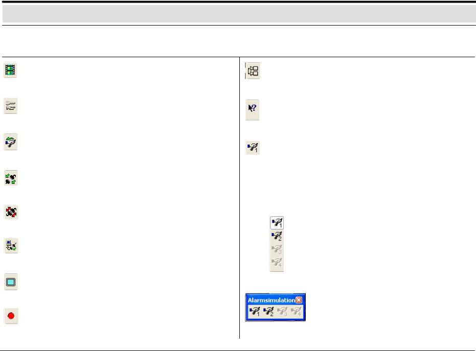
Basic window toolbar / alarm simulation bar in live image
Icon |
Name |
Explanation |
Icon |
Name |
Explanation |
|
|
|
|
|
|
Image |
Look at, search for, swap out or print |
archive |
saved images in local/remote archives. |
Configuration Hardware, image saving, image transmission, and user settings.
Not active with integrated operating station.
Alarm |
The |
configured alarm |
simulation |
||
simulation |
buttons will be called up. |
|
|
||
Connect |
with |
a |
remote |
station |
|
|
(network/ISDN/DSL/modem) |
|
|
||
Terminate |
established |
connection |
will |
be |
|
|
terminated. |
|
|
|
|
Local |
Connection will be established to the |
||||
connection |
local system. |
|
|
|
|
Full Screen |
Enlarges the image of the selected |
||||
mode |
camera to full–screen size. |
|
|
||
Save images |
Activate, deactivate automatic saving of |
||||
displayed |
all |
images |
displayed. |
With |
|
|
simultaneous generation of a separate |
||||
|
archive in the image archive with the |
||||
|
name <Computername>_normal. |
|
|||
Automatic |
Switchover of all cameras displayed. |
camera |
|
switchover |
|
Help |
If you place the mouse pointer over an |
|
object, you will receive help with that |
|
object. |
Alarm |
Buttons for the configured alarm |
simulation |
simulation signals or other configured |
|
actions. |
The alarm simulation bar can be embedded in the toolbar or free–standing.
Embedded
Alarm simulation 1 triggered
Alarm simulation 2 not triggered
Alarm simulation 3 and 4 not configured
Free–standing
BOSCH Security Systems GmbH |
– 8 – |
A1 02.03 |

Basic window toolbar / connection window in live image
The Status bar (lowermost line of the screen) contains help information about the menu you are currently using. It shows the name of the remote station to which an external connection has just been established.
The Title bar contains:
–the window title with the name of the selected station and
–the buttons to minimize, maximize and close the window.
Clicking minimizes the window and places it at the bottom edge of the screen.
Clicking restores the window to normal size.
Terminates the existing connection
Display of the existing / approved cameras
On the left side of the screen, you will find a list of the configured cameras.
Existing / approved cameras will be displayed in live image.
Display of the configured alarm inputs
The lower portion of the image displays all configured alarm inputs.
Configured alarm inputs are displayed in the live image
Contact input or video motion detector of a camera
Foyer card reader / barcode reader
on |
Configured relay outputs can be activated |
|
and deactivated by clicking with the right |
||
|
||
|
mouse button |
Status display of the configured alarm inputs
The statuses of all configured alarm inputs are displayed as follows.
no icon |
Input is in standby |
|
Input has triggered |
?Input does not exist as hardware
BOSCH Security Systems GmbH |
– 9 – |
A1 02.03 |
 Loading...