


MODEL 250SX NG and 250SX LP Temperature Modulated with Electronic Ignition Suitable for heating potable water only
Not approved for space heating purposes
(Intended for variable flow applications with multiple tapping points)
250 SX NG
250 SX LP
Warning: If the information in this manual is not followed exactly, a fire or explosion may result causing property damage, personal injury or death. Do not store or use gasoline or other flammable vapor and liquids in the vicinity of this or any other appliance.
|
Improper installation, |
adjustment, alteration, |
||
|
service or maintenance can cause injury or |
|||
|
property damage. Refer to this manual. |
For |
||
|
assistance or additional information consult a |
|||
|
qualified installer, service agency or the gas |
|||
JS |
supplier. |
|
|
|
In the Commonwealth |
of Massachusetts |
this |
||
(04.05) |
||||
product must be installed by a licensed plumber or |
||||
|
||||
057 |
gas fitter. |
|
|
|
|
|
|
||
607 |
Upon completion of the installation, these |
|||
|
||||
720 |
instructions should be handed to the user of the |
|||
appliance for future reference. |
|
|||
6 |
|
|||
|
|
|
||
What to do if you smell gas
•Close gas valve. Open windows.
•Do not try to light any appliance.
•Do not touch any electrical switch; do not use any phone in your building.
•If you cannot reach your gas supplier, call the fire department.
•Immediately call your gas supplier from a neighbor’s phone. Follow the gas supplier’s instructions
•Installation and service must be performed by a qualified installer, service agency or the gas supplier.
Index
Index
|
|
|
1 |
Warning |
|
|
|
|
||
1 |
Warning |
2 |
|
|
|
|
||||
|
|
|
|
|
|
|
|
|
|
|
|
|
|
|
|
|
Warning: If |
the |
information in |
this |
|
2 |
Appliance details |
4 |
|
|
|
|||||
|
|
|
manual is not followed exactly. A fire or |
|||||||
2.1 |
Features |
4 |
|
|
|
|||||
|
|
|
explosion may result causing property |
|||||||
2.2 |
250 SX Specifications (Technical data) |
4 |
|
|
|
|||||
|
|
|
||||||||
2.3 |
Dimensions and Minimum installation clearances |
6 |
|
|
|
damage, personal injury or death. |
|
|||
2.4 |
General rules to follow for safe operation |
7 |
|
|
|
|
|
|
|
|
|
|
|
|
|
|
|
|
|||
2.5 |
Proper location for installing your heater |
7 |
|
|
|
|
|
|
|
|
2.6 |
Clearances |
8 |
|
|
|
Warning: |
Improper |
installation, |
||
2.7 |
Mounting installation |
8 |
|
|
|
adjustment, |
alteration, |
service |
or |
|
2.8 |
Combustion air requirements |
8 |
|
|
|
maintenance |
can |
cause |
injury |
or |
2.9 |
Venting |
9 |
|
|
|
|||||
|
|
|
property damage. Refer to this manual. |
|||||||
2.9.1 |
Venting options |
11 |
|
|
|
|||||
2.10 |
Gas piping & connections |
15 |
|
|
|
For assistance or additional information |
||||
2.11 |
Gas line sizing |
17 |
|
|
|
consult a qualified installer, service |
||||
2.12 |
Measuring gas pressure |
17 |
|
|
|
agency or the gas supplier. |
|
|
||
2.13 |
Water connections |
18 |
|
|
|
Upon completion |
of the |
installation, |
||
2.14 |
Electrical connections |
19 |
|
|
|
|||||
|
|
|
these instructions should be handed to |
|||||||
2.15 |
Operating instructions |
19 |
|
|
|
|||||
2.16 |
For your safety read before operating your water heater |
19 |
|
|
|
the user of the appliance for future |
||||
2.17 |
Lighting and operating instructions |
19 |
|
|
|
reference. |
|
|
|
|
|
|
|
|
|
|
|
|
|
|
|
|
|
|
|
|
|
|
|
|
|
|
3Operation instructions
3.1Power
3.2Temperature selection
3.3Use of remote control accessory
3.4Operation
3.5Reset button
3.6Program button
3.7Locked condition
21 |
Featuring |
|
|
||
21 |
Electronic Ignition and Power Venting |
|
21 |
|
|
23 |
For your safety |
|
23 |
Do not store or use gasoline or other flammable, |
|
23 |
||
combustible or corrosive vapors and liquids in the |
||
23 |
||
23 |
vicinity of this or any other appliance. |
4 |
Maintenance and service |
24 |
|
|
|
5 |
Troubleshooting |
24 |
|
|
|
6 |
Electrical diagram |
27 |
|
|
|
7 |
250 SX Functional scheme |
28 |
|
|
|
8 |
Interior components diagram and parts list |
29 |
8.1 |
Interior components |
29 |
8.2 |
Components diagram |
30 |
8.3 |
Parts list |
31 |
9Special adjustment for measuring and adjusting CO2
|
levels |
32 |
9.1 |
Adjusting the unit |
32 |
9.1.1 |
CO2 measuring port |
32 |
9.1.2 |
Selecting adjustment mode |
32 |
|
|
|
10 |
Protecting the environment |
34 |
|
|
|
11 |
Twelve Year Limited Warranty |
35 |
Warning: Carefully plan where you install the heater. Correct combustion air supply and flue pipe installation are very important. If a gas appliance is not installed correctly, fatal accidents can result from lack of air, carbon monoxide poisoning or fire.
Warning: Exhaust gas must be vented to outside using proper vent material suitable for category III vent systems and temperatures up to 480°F. Vent and combustion air connector piping must be sealed gas-tight to prevent possibility of flue gas spillage, carbon monoxide emissions and risk of fire, resulting in severe personal injury or death.
Warning: Place the heater in a location where water leaks will do NO DAMAGE to adjacent areas or lower floors.
2 |
6 720 607 057 |

Warning
Warning: Field wiring connections and electrical grounding must comply with local codes, or in the absence of local codes, with the latest edition of the National Electric Code, ANSI/NFPA 70, or in Canada, all electrical wiring must comply with the local codes and the Canadian Electrical Code, CSA C22.1 Part 1.
Warning: Shock hazard line voltage is present. Before servicing the water heater, turn off the electrical power to the water heater at the main disconnect or circuit breaker. Failure to do so could result in severe personal injury or death.
What to do if you smell gas |
|
|
|
|
|
|
|
|
|
|
|
|
|
|
|
|
|
|
|
|
|
|
|
|
|
|
|
|
|
|
|
|
|
|
|
|
|
|
|
|
|
|
||
|
|
|
|
|
|
|
|
|
|
|
|
|
|
|
|
|
|
|
|
|
|
|
|
|
|
|
|
|
|
|
|
|
|
|
|
|
|
|
|
|
|
|||
• Close gas valve. Open windows. |
|
|
|
|
|
|
|
|
|
|
|
|
|
|
|
|
|
|
|
|
|
|
|
|
|
|
|
|
|
|
|
|
|
|
|
|
|
|
|
|
|
|
||
|
|
|
|
|
|
|
|
|
|
|
|
|
|
|
|
|
|
|
|
|
|
|
|
|
|
|
|
|
|
|
|
|
|
|
|
|
|
|
|
|
|
|||
|
|
|
|
|
|
|
|
|
|
|
|
|
|
|
|
|
|
|
|
|
|
|
|
|
|
|
|
|
|
|
|
|
|
|
|
|
|
|
|
|
|
|||
• Do not try to light any appliance. |
|
|
|
|
|
|
|
|
|
|
|
|
|
|
|
|
|
|
|
|
|
|
|
|
|
|
|
|
|
|
|
|
|
|
|
|
|
|
|
|
|
|
||
|
|
|
|
|
|
|
|
|
|
|
|
|
|
|
|
|
|
|
|
|
|
|
|
|
|
|
|
|
|
|
|
|
|
|
|
|
|
|
|
|
|
|||
• Do not touch any electrical switch; do not use any |
|
|
|
|
|
|
|
|
|
|
|
|
|
|
|
|||||||||||||||||||||||||||||
|
phone in your building. |
|
|
|
|
|
|
|
|
|
|
|
|
|
|
|
|
|
|
|
|
|
|
|
|
|
|
|
|
|
|
|
|
|
|
|
|
|
|
|
|
|
|
|
|
|
|
|
|
|
|
|
|
|
|
|
|
|
|
|
|
|
|
|
|
|
|
|
|
|
|
|
|
|
|
|
|
|
|
|
|
|
|
|
|
|
|
||
• Immediately call your gas supplier from a neighbor’s |
|
|
|
|
|
|
|
|
|
|
|
|
|
|
|
|
|
|
|
|
|
|||||||||||||||||||||||
|
|
|
|
|
|
|
|
|
|
|
|
|
|
|
|
|
||||||||||||||||||||||||||||
|
|
|
|
|
|
|
|
|
|
|
|
|
|
|
|
|
||||||||||||||||||||||||||||
|
phone. Follow the gas supplier’s instructions. |
|
|
|
|
|
|
|
|
|
|
|
|
|
|
|
|
|
|
|
|
|
|
|
|
|
||||||||||||||||||
|
|
|
|
|
|
|
|
|
|
|
|
|
|
|
|
|
|
|
||||||||||||||||||||||||||
• |
If you cannot reach your gas supplier, call the fire |
|
|
|
|
|
|
|
|
|
|
|
|
|
|
|
|
|
|
|
|
|
|
|
|
|
|
|
|
|
|
|
|
|
|
|
|
|
|
|||||
|
|
|
|
|
|
|
|
|
|
|
|
|
|
|
|
|
|
|
|
|
|
|
|
|
|
|
|
|
|
|
|
|
|
|
|
|
|
|||||||
|
department. |
|
Fig. 1 |
|
|
|
|
|
|
|
|
|
|
|
|
|
|
|
||||||||||||||||||||||||||
• |
Installation and service must be |
performed by a |
|
|
|
|
|
|
|
|
|
|
|
|
|
|
|
|
|
|||||||||||||||||||||||||
|
|
|
|
|
|
|
|
|
|
|
|
|
|
|
|
|
||||||||||||||||||||||||||||
|
qualified installer, service agency or the gas supplier. |
|
|
|
|
|
|
|
|
|
|
|
|
|
|
|
|
|||||||||||||||||||||||||||
|
|
|
|
|
|
|
|
|
|
|
|
|
|
|
|
|
||||||||||||||||||||||||||||
|
|
|
|
|
|
|
|
|
|
|
|
|
|
|
|
|
|
|
|
|
|
|
|
|
|
|
|
|
|
|
|
|
|
|
|
|
|
|
|
|
|
|
|
|
|
|
|
|
|
|
|
|
|
|
|
|
|
|
|
|
|
|
|
|
|
|
|
|
|
|
|
|
|
|
|
|
|
|
|
|
|
|
|
|
|
|
|
|
|
|
|
Warning: The heater |
must be |
|
|
|
|
|
|
|
|
|
|
|
|
|
|
|
|
|
|
|
|
|
|
|
|
|
|
|
|
|
|
|
|
|
|
|
|
|
|
|
|
|
|
|
|
|
|
|
|
|
|
|
|
|
|
|
|
|
|
|
|
|
|
|
|
|
|
|
|
|
|
|
|
|
|
|
|
|
|
|
|
|
|
|
|
||
|
|
|
|
|
|
|
|
|
|
|
|
|
|
|
|
|
|
|
|
|
|
|
|
|
|
|
|
|
|
|
|
|
|
|
|
|
|
|
|
|
|
|
||
|
|
|
|
|
|
|
|
|
|
|
|
|
|
|
|
|
|
|
|
|
|
|
|
|
|
|
|
|
|
|
|
|
|
|
|
|
|
|
|
|
|
|
||
|
|
disconnected from the gas supply |
|
|
|
|
|
|
|
|
|
|
|
|
|
|
|
|
|
|
|
|
|
|
|
|
|
|
|
|
|
|
|
|
|
|
|
|
|
|
|
|
|
|
|
|
piping system during any pressure |
|
|
|
|
|
|
|
|
|
|
|
|
|
|
|
|
|
|
|
|
|
|
|
|
|
|
|
|
|
|
|
|
|
|
|
|
|
|
|
|
|
|
|
|
|
|
|
|
|
|
|
|
|
|
|
|
|
|
|
|
|
|
|
|
|
|
|
|
|
|
|
|
|
|
|
|
|
|
|
|
|
|
|
|
|
||
|
|
|
|
|
|
|
|
|
|
|
|
|
|
|
|
|
|
|
|
|
|
|
|
|
|
|
|
|
|
|
|
|
|
|
|
|
|
|
|
|
|
|
||
|
|
testing of that system at test pressures |
|
|
|
|
|
|
|
|
|
|
|
|
|
|
|
|
|
|
|
|
|
|
|
|
|
|
|
|
|
|
|
|
|
|
|
|
|
|
|
|
|
|
|
|
|
|
|
|
|
|
|
|
|
|
|
|
|
|
|
|
|
|
|
|
|
|
|
|
|
|
|
|
|
|
|
|
|
|
|
|
|
|
|
|
|
||
|
|
|
|
|
|
|
|
|
|
|
|
|
|
|
|
|
|
|
|
|
|
|
|
|
|
|
|
|
|
|
|
|
|
|
|
|
|
|
|
|
|
|
||
|
|
equal to or more than 0.5 psig. |
|
|
|
|
|
|
|
|
|
|
|
|
|
|
|
|
|
|
|
|
|
|
|
|
|
|
|
|
|
|
|
|
|
|
|
|
|
|
|
|
|
|
|
|
|
|
|
|
|
|
|
|
|
|
|
|
|
|
|
|
|
|
|
|
|
|
|
|
|
|
|
|
|
|
|
|
|
|
|
|
|
|
|
|
|
|
|
|
|
|
|
|
|
|
|
|
|
|
|
|
|
|
|
|
|
|
|
|
|
|
|
|
|
|
|
|
|
|
|
|
|
|
|
|
|
|
|
|
|
|
|
|
FCC:
This device complies with Part 15 of the FCC rules. Operation is subject to the following two conditions: (1) This device may not cause harmful interference, and (2) this device must accept any interference received, including interference that may cause undesired operation.
Caution: Any changes or modifications not expressly approved by the party responsible for compliance could void the user’s authority to operate the equipment.
Fig. 2
6 720 607 057 |
3 |
Appliance details
2Appliance details
2.1Features
Parts
•Touch Pad interface control
•High power pre-mix compact burner with low Nox emissions
•Modulating Gas Valve with constant gas:air ratio control
•Modulating water valve for improved comfort and temperature control.
Safety
•Flame sensor (ionization) rod
•Overheat sensor
•Temperature limiter
•Fan speed monitoring.
High Quality Materials for Long Working Life
•Copper heat exchanger
•Ceramic Burner output
•Automatic overheating protection shut-off sensor
•Compact space saver: mounts on a wall with a supplied bracket.
•Easily removable one-piece cover.
Features
•LCD Display
•On/Off and Temperature control switches
•Reset button
•Program Key (Selectable temperature default)
•Failure codes for easy diagnostic and repair. Accessories
•Optional wireless remote control accessory to operate with the appliance
•Vent termination kit.
BOSCH is constantly improving its
iproducts, therefore specifications are subject to change without prior notice.
2.2250 SX Specifications (Technical data)
Approved in US/Canada
Capacity
Maximum flow rate: 6.35 GPM (24 l/min) at a 45°F (25°C) rise.
Maximum output
142,968 Btu/h (41.8 kW)
Maximum input
175,000 Btu/h (51.2 kW)
Efficiency in %
Recovery efficiency 86.5%
Min. Output
31,131 Btu/h (9.1 kW)
Temperature Control
Selection range: 100°F (38°C) - 140°F (60°C)
Default temperature: 122°F (50°C)
Stability: +/- 2°F (+/- 1°C)
Gas Requirement
Gas connection (inches) - ¾”
Inlet gas pressure under operation (with a high hot water flow rate)*
•Propane: 11” - 14” water column
•Natural Gas: 5” - 14” water column
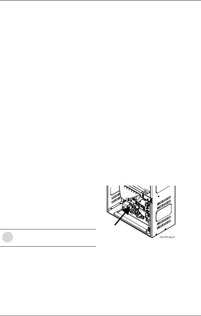
•Gas pressure measuring point inside the appliance at the gas valve inlet.
* Testing with a manometer, operate other gas equipment on the same gas supply. Gas pressures lower than 5" W.C. for Natural Gas or 11" W.C. for LPG will result in insufficient degree rise to the hot water being used. See Measuring Gas Pressure, chapter 2.12.
Fig. 3 Gas pressure measuring point
Venting
See chapter 2.9 for Venting on page 9.
Water
•Hot water connection (inches) - ¾”
•Cold water connection (inches) - ¾”
•Water valve material: Polymer (PPS) (Polypropylene Sulfid)
•Minimum water flow: 0.8 gallon/minute (3 l/m)
4 |
6 720 607 057 |
Appliance details
•Minimum recommended water pressure: 30 PSI (2.07 bar)
•Connections:
– Bottom of heater
Combustion
•NOx ≤ 55 ppm
•CO ≤ 250 ppm
•CO2 level set from factory, see chapter 9.1.
Dimensions
•Depth (in): 8 ½” (220 mm)
•Width (in): 15 ¾” (400 mm)
•Height (in): 23 ½” (600 mm)
•Weight: 47 pounds (21 kg).
Gas types
Natural Gas. LP Gas.
Converting the gas type can only be done by a certified gas technician with a calibrated CO2 analyzer. Call CEC for conversion instructions.
Voltage
120 V AC (50/60 Hz)
Amperage
IDLE - 40 mA
Operation - ≤ 2,5 A
Noise
≤ 50 db (A)
Safety devices
•Flame failure device (ionization flame rod sensor)
•Pressure relief valve (supplied with heater)
•Over heat prevention (temperature limiter).
Water resistant
IP X4 (protection against water drops)
UNPACKING THE 250 SX HEATER
This heater is packed securely.
The box includes:
•Pressure relief valve
•Bracket for wall hanging the heater
•Exhaust vent adaptor (with 4 screws and gasket provided)
•Combustion air inlet adaptor (with 3 screws and gasket provided)
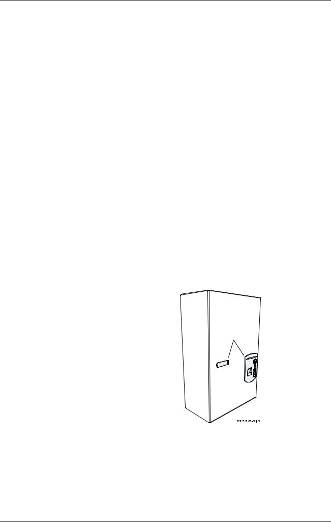
•Plastic decal shields for covering front cover screws and control panel, installer should affix these decals to the front of the unit after installation is complete. See Fig. 4
•Installation manual
•Product registration card.
Do not lose this manual. Please complete and return the enclosed product registration card.
Before installing the unit, be certain you have the correct heater for your type of Gas - Propane or Natural Gas. Identification labels are found on the shipping box, and on the rating plate which is located on the right side panel of the cover.
To remove front cover
•Loosen the two Philips head screws located on front panel (beneath plastic decal shields if they are already attached, see Fig. 4)
•Lift front cover panel upward and remove.
Plastic decals
Fig. 4 Remove front cover
6 720 607 057 |
5 |
Appliance details
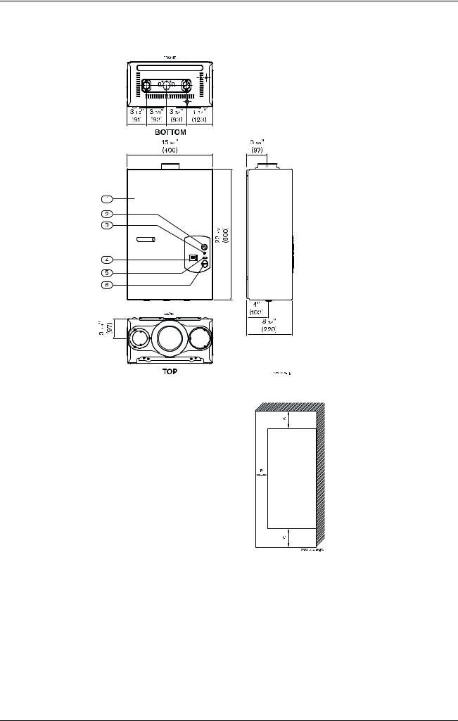
2.3Dimensions and Minimum installation clearances
Fig. 5 Dimensions
1Cover
2On/Off switch
3 Reset button
4 LCD display
5Program button
6Temperature buttons
Fig. 6 Minimum clearances
|
Model 250 SX |
TOP (A) |
12” |
FRONT (B) |
4” |
BACK |
0” |
SIDES |
4” |
FLOOR (C) |
12” |
VENT DIAMETER |
3” |
Table 1 Minimum clearances
6 |
6 720 607 057 |

Appliance details
2.4General rules to follow for safe operation
B1. You should follow these instructions when you install your heater. In the United States: The installation must conform with local codes or, in the absence of local codes, the National Fuel Gas Code ANSI Z223.1/NFPA 54.
In Canada: The Installation should conform with CGA B149.(1,2) INSTALLATION CODES and /or local installation codes.
B2. Carefully plan where you install the heater. Correct combustion air supply and vent pipe installation are very important. If not installed correctly, fatal accidents can be caused by lack of air, carbon monoxide poisoning or fire.
B 3. When the unit is installed indoors and ROOM SEALED (twin pipe) it is permitted to be located in bathrooms, bedrooms and occupied rooms that are normally kept closed. See chapter 2.9. If the unit will be installed indoors and use indoor combustion air, the place where you install the heater must have enough ventilation. The National Fire Codes do not allow UNSEALED gas fired water heater installations in bathrooms, bedrooms or any occupied rooms normally kept closed. See chapter 2.5 and 2.8.
B 4. You must vent your heater. See section on VENTING.
B 5. The appliance must be isolated from the gas supply piping system by closing its individual manual gas shutoff valve (not supplied with heater) during any pressure testing at pressures in excess of ½ Psig (3.5 kPa).
The appliance and its gas connection must be leak tested before placing the appliance in operation.
B 6. Keep water heater area clear and free from combustibles and flammable liquids. Do not locate the heater over any material which might burn.
B7. Correct gas pressure is critical for the optimum operation of this heater. Gas piping must be sized to provide the required pressure at the maximum output of the heater, while all the other gas appliances are in operation. Check with your local gas supplier, and see the section on connecting the gas supply.
B8. Should overheating occur or the gas supply fail to shut off, turn off the gas supply at the manual gas shut off valve, on the gas line. Note: manual gas shutoff valve is not supplied with the heater.
B9. Do not use this appliance if any part has been underwater. Immediately call a qualified service technician to inspect the appliance and to replace any part of the control system and any gas control which has been underwater
2.5Proper location for installing your heater
Carefully select the location of the water heater. For your safety and for proper heater operation, you must provide combustion air to the heater and a proper exhaust vent system.
Follow the guidelines below:
B 1. Locate the heater where venting, gas and plumbing connections are feasible and convenient.
B 2. It is strongly recommended that the heater be installed as a ROOM SEALED heater (twin pipe). If the heater will be installed as an UNSEALED heater (single pipe) than National building codes require that you do not install this appliance in bathrooms, bedrooms or any occupied rooms normally kept closed. Heaters that are UNSEALED require a considerable amount of combustion air, see chapter 2.8. If installing the heater UNSEALED within a laundry room, be certain that the dryer is properly vented. Failure to properly vent a dryer could result in a gradual accumulation of lint build up inside the combustion chamber of the heater.
B3. The hot water lines should be kept short to save energy. Centrally locating the water heater is best. It is always best to have hot water lines insulated.
Warning: The water in this water heater is cold and always remains cold except for the times that hot water is being used DO NOT INSTALL IN AN AREA WHERE IT COULD FREEZE. Drain the heater entirely if freezing temperatures are anticipated in area where heater is installed by disconnecting both the inlet and outlet connections at the bottom of heater.
To prevent any freeze damage, introduce short bursts of compressed air (20-40psi) through these connections to remove the residual water in the horizontal pipes and water valve.
Warning: Flammable materials, gasoline, pressurized containers, or any other items or articles that are potential fire hazards must NOT be placed on or adjacent to the heater. The appliance area must be kept free of all combustible materials, gasoline and other flammable vapors and liquids.
6 720 607 057 |
7 |
Appliance details
2.6Clearances
The 250 SX is design certified for installation on a combustible wall (see 2.7 Mounting installation) provided the floor covering below the heater is noncombustible. For installations in an alcove or closet, maintain the minimum clearances to combustible and non-combustible materials listed below. See also Fig. 6.
A.Top 12 inches (306 mm)
B.Front 4 inches (102 mm)
C.Back 0 inches
D.Sides 4 inches (102 mm)
E.Bottom 12 inches (306 mm)
Clearances from any exhaust vent pipe are dependent upon the clearance requirements of the stainless steel vent pipe manufacturer. Single wall stainless steel (AL29-4C) vent pipe (vent type rated for Category III appliances) must be used when exhaust venting this appliance. See 2.9 Venting.
2.7Mounting installation
Warning: before starting installation:
B check that there are no loose parts inside the appliance
Bensure that gas pipe, gas valve, mixer, fan and burner have no damage and are properly fitted.
Front cover should be removed (see
iinstructions on page 4) in order to inspect components visually.
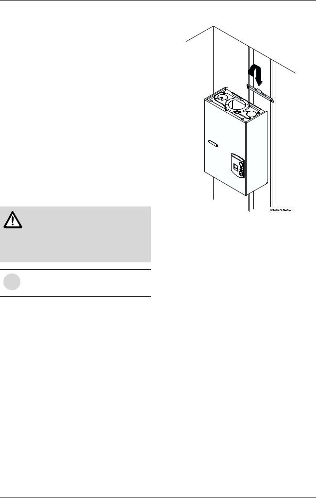
The 250 SX is design certified for mounting on a wall. Secure the wall mounting bracket provided with the heater to a wall surface. See Fig. 7.
Do not install this appliance on a carpeted wall or over floor covering which is combustible, such as carpet. The heater must be mounted on a wall using appropriate anchoring materials.
If the mounting bracket is unable to line up on two wall studs it is recommended that support board(s), either 1x4's or ½" (minimum) plywood first be attached across a pair of studs and then the heater should be attached to the support boards. The heater should be kept level on the wall surface. See Fig. 7.
Expansion and contraction of piping due to changing water temperature in the pipes imparts movement to the heater which, if mounted directly to a brittle, friable board, such as plasterboard, can cause failure of mounting.
Before installing the unit, be certain you have the correct heater for your type of Gas - Propane or Natural Gas. Identification labels are found on the shipping box, and on the rating plate which is located on the right side panel of the cover.
Fig. 7 Mounting the heater
2.8Combustion air requirements
The 250 SX is a sealed water heater and it is recommended that outdoor combustion air be piped to the unit. When combustion air is piped to the unit (TWIN PIPE SYSTEM) the combustion air pipe system may be constructed of either 3" PVC, aluminum or galvanized pipe. See Fig. 11, 12 and 13. Select a point for building penetration being sure that the necessary clearance on the outside of the building, between the combustion air pipe and the exhaust vent terminator of the appliance, can be maintained, see Fig. 16. NOTE: Observe all local building codes when penetrating a building wall.
NOTE: The combustion air inlet location on the side of a building must never be less than 3 feet away from the units exhaust vent terminator, see Fig. 16 Table 3.
The heater has the ability to operate without combustion air being piped to it from the outside, provided there is an adequate amount of combustion air available in the room area. Observe the following instructions concerning combustion air when following the SINGLE PIPE (exhaust venting only) SYSTEM only and follow Fig. 14 and 15 for proper setup.
•Appliances located in unconfined spaces:
–a) An unconfined space is one whose volume is greater than 50 cubic feet (1.42 cubic meter) per 1000 Btu per hour (292.81 Watts) of the combined rating of all appliances installed in the space. That would be 8750 cubic feet (247.8 cubic meter) for the 250 SX alone.
8 |
6 720 607 057 |
Appliance details
–b) In unconfined spaces in buildings of conventional frame, masonry, or metal construction, infiltration air is normally adequate to provide air for combustion.
•Appliances located in confined spaces:
The confined space must be provided with two permanent openings, one commencing within 12 inches (304.8mm) of the top and one commencing within 12 inches (304.8mm) of the bottom of the enclosure. Each opening must have a minimum free area of one square inch per:
–1000 Btu/hr (292.81 Watts) if all air is taken from inside the building
–2000 Btu/hr (585.62 Watts) if all air is taken from the outside by horizontal ducts
–4000 Btu/hr (1171.24 Watts)if all air is taken from the outside by direct openings or vertical ducts
Or the confined space must be provided with one permanent opening or duct that is within 12 inches (304.8mm) of the ceiling of the enclosure. This opening must have a minimum free area of one square inch per:
–3000 Btu/hr (878.43 Watts) if all air is taken from the outside by a direct opening or vertical duct.
Louvers, grills and screens have a blocking effect. If the effective free area is not known, increase the sizes of your openings by 75% if your louvers are wood and by 30% if your louvers are metal. Refer to the National Fuel Gas Code for complete information. In buildings of tight construction all air should be taken from outside.
2.9Venting 
Warning: Do not reduce the vent (exhaust and combustion) pipe sizes and do not common vent with any other vented appliance or stove.
NOTE: This appliance's exhaust must be vented to the outside with a sealed 3" stainless steel vent pipe (AL29-4C). The appliance's flue gasses are under positive pressure and must travel through a stainless steel 3" pipe that is sealed gas tight. Stainless steel vent pipe is equipped with sealing gaskets for ease of installation, proper safety and durability. The heater shall not be vented in combination with any other appliance; the appliance must only be vented with a dedicated sealed vent system.
Caution: The vent system must be installed by a qualified agency in accordance with these instructions. If improperly installed a hazardous condition such as explosion or Carbon Monoxide poisoning could result. CEC will not be responsible for improperly installed appliances.
Establish vent clearances that comply with the vent manufacturer's specifications. In all cases follow local codes. See table 2.
6 720 607 057 |
9 |

Appliance details
The maximum flue gas exhaust temperature on the 250 SX is 437°F (225°C)
Venting |
Exhaust |
* Exhaust |
* Exhaust |
Combustion |
Combustion |
Vent pipe |
Vent pipe |
Options |
vent |
vent |
vent |
air pipe |
air pipe |
clearances |
clearances |
|
diameter |
maximum |
minimum |
diameter |
maximum |
within an |
within an |
|
and |
length |
length |
and material |
length |
unenclosed |
enclosed |
|
material |
|
|
|
|
space |
space |
|
|
|
|
|
|
|
|
Room |
3 inch |
26 feet (8 |
3 feet |
3 inch PVC, |
26 feet (8 |
** See vent |
** See vent |
sealed |
stainless |
m) with one |
|
aluminum or |
m) with one |
manufacturer's |
manufacturer's |
(twin pipe) |
steel |
elbow. Less |
|
galvanized |
elbow. Less |
specifications |
specifications |
|
(AL29-4C) |
2½ feet for |
|
pipe |
2½ feet for |
|
|
|
sealed vent |
each |
|
|
each |
|
|
|
pipe |
additional |
|
|
additional |
|
|
|
|
90° elbow |
|
|
90° elbow |
|
|
Open |
3 inch |
26 feet (8 |
3 feet |
See |
See |
** See vent |
** See vent |
combustion |
stainless |
m) with one |
|
chapter 2.8 |
chapter 2.8 |
manufacturer's |
manufacturer's |
(single |
steel |
elbow. Less |
|
|
|
specifications |
specifications |
pipe) |
(AL29-4C) |
2½ feet for |
|
|
|
|
|
|
sealed vent |
each |
|
|
|
|
|
|
pipe |
additional |
|
|
|
|
|
|
|
90° elbow |
|
|
|
|
|
|
|
|
|
|
|
|
|
Exhaust vent is always fan assisted. Installation of exhaust vent and combustion air piping may be run vertically or horizontally and in separate directions if required.
* A maximum of three 90 degree elbows are permitted in the total vent length. The total vent length must be reduced by 1 ¼ feet for every 45° elbow used in the vent system.
** Stainless steel (AL29-4C) vent pipe is manufacturerd by Z-Flex, Protech and Heat Fab. NOTE: clearance distances are variable depending if the vent pipe is installed in an enclosed or unenclosed space, the exhaust flue gas temperature and the orientation of the vent pipe.
Table 2
10 |
6 720 607 057 |
Appliance details
The appliance should be located as close to the point of termination as possible. The maximum vent length is 26 feet (8 m) with one 90 degree elbow. Subtract 2½ feet from the total vent length for each additional 90° elbow used (a maximum of three 90° elbows are permitted in the total vent length), or subtract 1 ¼ feet for every 45° elbow used. Horizontal sections of vent must pitch ¼" for every foot of horizontal length and be supported at 4 foot intervals with overhead hangers.
Note: Listed thimbles or collars are necessary to pass through wall and ceiling partitions. If the vent system passes through combustible areas where the vent clearance requirements cannot be maintained, it is permissible to chase straight sections of sealed 3 inch single wall vent through 4 inch (or greater) Type-B vent. The distance to combustibles using this chase technique is 1 inch. Note: Type-B vent should never be used as the actual exhaust vent system for the appliance, as it is not gas tight.
Minimum exhaust vent size and length
The use of a 90 degree elbow is equivalent to 2 ½ ft in vent length.
The use of 45 degree elbow is equivalent to 1 ¼ ft in vent length.
Fig. 8
Maximum exhaust vent and combustion air inlet lengths
Fig. 9
Note: reduce 2½ ft for each 90° elbow used after the first one, reduce 1 ¼ ft for each 45° elbow.
Vent Safety System
The 250 SX will shut down if inadequate exhaust venting is detected or a lack of combustion air is provided to the unit; see troubleshooting section on
page 24. See error code to confirm error, correct the problem and then reset the heater before operating.
Attaching the exhaust and air inlet connection adaptors to the top of the heater
Fig. 10
Fig. 11
BAttach the flue gas exhaust accessory (8 705 504
114)to the top of the unit (position 1) using the 4 screws and gasket provided, and fully insert 3" stainless steel vent pipe into the accessory and tighten the clamp (position 2).
B Attach the combustion air inlet accessory (8 705 504 115) to the top of the unit (position 3) using the 3 screws and gasket provided, and fully insert 3" combustion air pipe into the accessory and tighten the clamp (position 4). NOTE: The appliance has the possibility to mount the combustion air inlet accessory on the top right or on the top left side of the heater. The combustion air inlet that is not used must be kept sealed.
2.9.1Venting options
Installing this water heater as a room sealed (TWIN PIPE SYSTEM) is the recommended method. Contact CEC or dealer for available vent termination kits and vent materials for this water heater.
Exhaust venting shall be done with 3”
istainless steel (AL29-4C) vent pipe.
6 720 607 057 |
11 |
 Loading...