


BM 2610925945 6-05 6/10/05 |
10:30 AM Page 1 |
|
IMPORTANT: |
IMPORTANT : |
IMPORTANTE: |
Read Before Using |
Lire avant usage |
Leer antes de usar |
Operating/Safety Instructions |
||
Consignes de fonctionnement/sécurité |
||
Instrucciones de funcionamiento y seguridad |
||
1659 |
|
|
1661 |
|
|
Call Toll Free |
Pour renseignement des |
Llame gratis para |
for Consumer Information |
consommateurs et centres |
obtener información |
& Service Locations |
de service, appelez au |
para el consumidor y |
|
numéro gratuit : |
ubicaciones de servicio |
1-877-BOSCH99 (1-877-267-2499) www.boschtools.com |
||
For English |
Parlez-vous français? |
¿Habla español? |
See page 2 |
Voir page 19 |
Ver página 36 |
BM 2610925945 6-05 6/10/05 10:30 AM Page 2
General Safety Rules
! WARNING Read all instructions. Failure to follow all instructions listed below may result in electric shock, fire and/or serious injury. The term “power tool” in
all of the warnings listed below refers to your mains-operated (corded) power tool or batteryoperated (cordless) power tool.
SAVE THESE INSTRUCTIONS
Work area safety
Keep work area clean and well lit.
Cluttered or dark areas invite accidents.
Do not operate power tools in explosive atmospheres, such as in the presence of flammable liquids, gases or dust. Power tools create sparks which may ignite the dust or fumes.
Keep children and bystanders away while operating a power tool. Distractions can cause you to lose control.
Electrical safety
Power tool plugs must match the outlet. Never modify the plug in any way. Do not use any adapter plugs with earthed (grounded) power tools. Unmodified plugs and matching outlets will reduce risk of electric shock.
Avoid body contact with earthed or grounded surfaces such as pipes, radiators, ranges and refrigerators. There is an increased risk of electric shock if your body is earthed or grounded.
Do not expose power tools to rain or wet conditions. Water entering a power tool will increase the risk of electric shock.
Do not abuse the cord. Never use the cord for carrying, pulling or unplugging the power tool. Keep cord away from heat, oil, sharp edges or moving parts.
Damaged or entangled cords increase the risk of electric shock.
When operating a power tool outdoors, use an extension cord suitable for outdoor use. Use of a cord suitable for outdoor use reduces the risk of electric shock.
Do not use AC only rated tools with a DC power supply. While the tool may appear to work, the electrical components of the AC rated tool are likely to fail and create a hazard to the operator.
If operating the power tool in damp locations is unavoidable a Ground Fault Circuit Interrupter (GFCI) must be used to supply the power to your tool. GFCI and personal protection devices like electrician’s rubber gloves and footwear will further enhance your personal safety.
Personal safety
Stay alert, watch what you are doing and use common sense when operating a power tool. Do not use a power tool while you are tired or under the influence of drugs, alcohol or medication. A moment of inattention while operating power tools may result in serious personal injury.
Use safety equipment. Always wear eye protection. Safety equipment such as dust mask, non-skid safety shoes, hard hat, or hearing protection used for appropriate conditions will reduce personal injuries.
Avoid accidental starting. Ensure the switch is in the off-position before plugging in. Carrying power tools with your finger on the switch or plugging in power tools that have the switch on invites accidents.
Remove any adjusting key or wrench before turning the power tool on. A wrench or a key left attached to a rotating part of the power tool may result in personal injury.
Do not overreach. Keep proper footing and balance at all times. This enables better control of the power tool in unexpected situations.
Dress properly. Do not wear loose clothing or jewelry. Keep your hair, clothing and gloves away from moving parts. Loose clothes, jewelry or long hair can be caught in moving parts.
If devices are provided for the connection of dust extraction and collection facilities, ensure these are connected and properly
-2-
BM 2610925945 6-05 6/10/05 10:30 AM Page 3
used. Use of these devices can reduce dustrelated hazards.
Keep handles dry, clean and free from oil and grease. Slippery hands cannot safely control the power tool.
Power tool use and care
Do not force the power tool. Use the correct power tool for your application.
The correct power tool will do the job better and safer at the rate for which it was designed.
Do not use the power tool if the switch does not turn it on and off. Any power tool that cannot be controlled with the switch is dangerous and must be repaired.
Disconnect the plug from the power source and/or the battery pack from the power tool before making any adjustments, changing accessories, or storing power tools. Such preventive safety measures reduce the risk of starting the power tool accidentally.
Store idle power tools out of the reach of children and do not allow persons unfamiliar with the power tool or these instructions to operate the power tool.
Power tools are dangerous in the hands of untrained users.
Maintain power tools. Check for misalignment or binding of moving parts, breakage of parts and any other condition that may affect the power tools operation. If damaged, have the power tool repaired before use. Many accidents are caused by poorly maintained power tools.
Keep cutting tools sharp and clean.
Properly maintained cutting tools with sharp cutting edges are less likely to bind and are easier to control.
Use the power tool, accessories and tool bits etc., in accordance with these instructions and in the manner intended for the particular type of power tool, taking into account the working conditions and the work to be performed.
Use of the power tool for operations different from those intended could result in a hazardous situation.
Use clamps or other practical way to secure and support the workpiece to a stable platform. Holding the work by hand or against your body is unstable and may lead to loss of control.
Battery tool use and care
Recharge only with the charger specified by the manufacturer. A charger that is suitable for one type of battery pack may create a risk of fire when used with another battery pack.
Use battery tools only with specifically designated battery packs. Use of any other battery packs may create a risk of injury and fire.
When battery pack is not in use, keep it away from other metal objects like paper clips, coins, keys, nails, screws, or other small metal objects that can make a connection from one terminal to another.
Shorting the battery terminals together may cause burns or a fire.
Under abusive conditions, liquid may be ejected from the battery, avoid contact. If contact accidentally occurs, flush with water. If liquid contacts eyes, additionally seek medical help. Liquid ejected from the battery may cause irritation or burns.
Ensure the switch is in the off position before inserting battery pack. Inserting the battery pack into power tools that have the switch on invites accidents.
Service
Have your power tool serviced by a qualified repair person using only identical replacement parts. This will ensure that the safety of the power tool is maintained.
Develop a periodic maintenance schedule for your tool. When cleaning a tool be careful not to disassemble any portion of the tool since internal wires may be misplaced or pinched or safety guard return springs may be improperly mounted. Certain cleaning agents such as gasoline, carbon tetrachloride, ammonia, etc. may damage plastic parts.
SAVE THESE INSTRUCTIONS
-3-
BM 2610925945 6-05 6/10/05 10:30 AM Page 4
Safety Rules for Circular Saws
! WARNING Read all safety warnings and all instructions.
Cutting procedures
! |
DANGER |
Keep hands away from |
|
cutting area and blade. |
|||
|
|
Keep your second hand on auxiliary handle, or motor housing. If hands are holding the saw, they cannot be cut by the blade.
This product is intended to cut wood and wood-like products only. Dust build up around the lower guard and hub from other materials (plastic, masonry or metal) may disable the lower guard operation.
Do not reach underneath the workpiece.
The guard cannot protect you from the blade below the workpiece.
NEVER hold piece being cut in your hands or across your leg. Secure the workpiece to stable platform. It is important to support the work properly to minimize body exposure, blade binding, or loss of control.
Hold power tool by the insulated gripping surfaces when performing an operation where the cutting tool may contact hidden wiring or it own cord. Contact with a "live" wire will also make exposed metal parts of the tool “live” and shock the operator.
When ripping always use a rip fence or straight edge guide. This improves accuracy of cut and reduces the chance for blade binding.
Always use blades with correct size and shape (diamond vs. round) of arbor holes.
Blades that do not match the mounting hardware of the saw will run eccentrically, causing loss of control.
Never use damaged or incorrect blade washers or bolts. The blade washers and bolt were specially designed for your saw, for optimum performance and safety of operation.
Inspect the condition and quality of the wood and remove all nails from lumber before cutting. Wet lumber, green lumber or pressure treated lumber require special attention during cutting operation to prevent kickback.
Hold the saw firmly to prevent loss of control. Figures in this manual illustrate typical hand support of the saw.
Depending upon use, the switch may not last the life of the saw. If the switch should fail in the “OFF” position, the saw may not start. If it should fail while the saw is
running, the saw may not shut off. If either occurs, unplug the saw immediately and do not use until repaired.
This circular saw should not be mounted to a table and converted to a table saw.
Circular saws are not designed or intended to be used as table saws.
Kickback and related warnings
Causes and operator prevention of kickback:
Kickback is a sudden reaction to a pinched, bound or misaligned saw blade, causing an uncontrolled saw to lift up and out of the workpiece toward the operator.
When the blade is pinched or bound tightly by the kerf closing down, the blade stalls and the motor reaction drives the unit rapidly back toward the operator.
If the blade becomes twisted or misaligned in the cut, the teeth at the back edge of the blade can dig into the top surface of the wood causing the blade to climb out of the kerf and jump back toward the operator.
Kickback is the result of tool misuse and/or incorrect operating procedures or conditions and can be avoided by taking proper precautions as given below:
Maintain a firm grip with both hands on the saw and position your body and arm to allow you to resist kickback forces. Position your body to either side of the blade, but not in line with the blade.
Kickback could cause the saw to jump backwards, but kickback forces can be controlled by the operator, if proper precautions are taken.
When blade is binding, or when interrupting a cut for any reason, release the trigger and hold the saw motionless in the material until the blade comes to a complete stop. Never attempt to remove the saw from the work or pull the saw backward while the blade is in motion or kickback may occur.
Investigate and take corrective action to eliminate the cause of blade binding.
When restarting a saw in a workpiece, center the saw blade in the kerf and check that saw teeth are not engaged into the material. If saw blade is binding, it may walk up or kickback from the workpiece as the saw is restarted.
-4-
BM 2610925945 6-05 6/10/05 10:30 AM Page 5
Support large panels to minimize the risk of blade pinching and kickback. Large panels tend to sag under their own weight. Supports must be placed under the panel on both sides, near the line of cut and near the edge of the panel.
Do not use dull or damaged blade.
Unsharpened or improperly set blades produce narrow kerf causing excessive friction, blade binding and kickback.
Blade depth and bevel adjusting locking levers must be tight and secure before making cut. If blade adjustment shifts while cutting, it may cause binding and kickback.
Use extra caution when making a “Plunge Cut” into existing walls or other blind areas. The protruding blade may cut objects that can cause kickback.
The blade washers and the bolt on your saw have been designed to work as a clutch to reduce the intensity of a kickback. Understand the operation and settings of the VARI-TORQUE CLUTCH. The proper setting of the clutch, combined with firm handling of the saw will allow you to control kickback.
Never place your hand behind the saw blade. Kickback could cause the saw to jump backwards over your hand.
Do not use the saw with an excessive depth of cut setting. Too much blade exposure increases the likelihood of the blade twisting in the kerf and increases the surface area of the blade available for pinching that leads to kickback.
KI 


 CKBACK
Lower guard function
Check lower guard for proper closing before each use. Do not operate saw if lower guard does not move freely and close instantly. Never clamp or tie the lower guard into the open position. If saw is
accidentally dropped, lower guard may be bent. Raise the lower guard only with the Lower Guard Lift Lever and make sure it moves freely and does not touch the blade or any other part, in all angles and depths of cut.
Check the operation of the lower guard spring. If the guard and the spring are not operating properly, they must be serviced before use. Lower guard may operate sluggishly due to damaged parts, gummy deposits, or a buildup of debris.
Lower guard should be retracted manually only for special cuts such as “Plunge Cuts” and “Compound Cuts”. Raise lower guard by lower guard Lift lever and as soon as blade enters the material, lower guard must be released. For all other sawing, the lower guard should operate automatically.
Always observe that the lower guard is covering the blade before placing saw down on bench or floor. An unprotected, coasting blade will cause the saw to walk backwards, cutting whatever is in its path. Be aware of the time it takes for the blade to stop after switch is released.
Do not run the tool while carrying it at your side. Lower guard may be opened by a contact with your clothing. Accidental contact with the spinning saw blade could result in serious personal injury.
Periodically remove the blade, clean the upper, lower guards and the hub area with kerosene and wipe it dry, or blow it clean with compressed air. Preventive maintenance and properly operating guard will reduce the probability of an accident.
! WARNING Some dust created by power sanding, sawing,
grinding, drilling, and other construction activities contains chemicals known to cause cancer, birth defects or other reproductive harm. Some examples of these chemicals are:
•Lead from lead-based paints,
•Crystalline silica from bricks and cement and other masonry products, and
•Arsenic and chromium from chemicallytreated lumber.
Your risk from these exposures varies, depending on how often you do this type of work. To reduce your exposure to these chemicals: work in a well ventilated area, and work with approved safety equipment, such as those dust masks that are specially designed to filter out microscopic particles.
-5-
BM 2610925945 6-05 6/10/05 10:30 AM Page 6
Battery/Charger
Before using battery charger, read all instructions and cautionary markings on
(1) battery charger, (2) battery pack, and
(3) product using battery.
Use only the charger which accompanied your product or direct replacement as listed in the catalog or this manual. Do not substitute any other charger. Use only Bosch approved chargers with your product. See Functional Description and Specifications.
Do not disassemble charger or operate the charger if it has received a sharp blow, been dropped or otherwise damaged in any way. Replace damaged cord or plugs immediately. Incorrect reassembly or damage may result in electric shock or fire.
Do not recharge battery in damp or wet environment. Do not expose charger to rain or snow. If battery case is cracked or otherwise damaged, do not insert into charger. Battery short or fire may result.
Charge only Bosch approved rechargeable batteries. See Functional Description and Specifications. Other types of batteries may burst causing personal injury and damage.
Charge battery pack in temperatures above +40 degrees F (4 degrees C) and below +105 degrees F (41 degrees C). Store tool and battery pack in locations
where temperatures do not go below 40 degrees F (4 degrees C) or will no exceed 120 degrees F (49 degrees C). Allow battery pack to return to room temperature before attempting to charge.This is important to prevent serious damage to the battery cells.
Battery leakage may occur under extreme usage or temperature conditions. Avoid contact with skin and eyes. The battery liquid is caustic and could cause chemical burns to tissues. If liquid comes in contact with skin, wash quickly with soap and water, then with lemon juice or vinegar. If the liquid contacts your eyes, flush them with water for a minimum of 10 minutes and seek medical attention.
Place charger on flat non-flammable surfaces and away from flammable materials when re-charging battery pack.
The charger and battery pack heat during charging. Carpeting and other heat insulating surfaces block proper air circulation which may cause overheating of the charger and battery pack. If smoke or melting of the case are observed unplug the charger immediately and do not use the battery pack or charger.
Use of an attachment not recommended or sold by Bosch may result in a risk of fire, electric shock or injury to persons.
Battery Care
When batteries are not in ! WARNING tool or charger, keep them
away from metal objects. For example, to protect terminals from shorting DO NOT place batteries in a tool box or pocket with nails, screws, keys, etc. Fire or injury may result.
To prevent fire or injury ! WARNING when batteries are not in
tool or charger, always place protective cap onto end of battery pack. Protective cap, guards against terminal shorting.
DO NOT PUT BATTERIES INTO FIRE OR EXPOSE TO HIGH HEAT. They may explode.
-6-
BM 2610925945 6-05 6/10/05 10:30 AM Page 7
Battery Disposal
Do not attempt to disas- ! WARNING semble the battery or
remove any component projecting from the battery terminals. Fire or injury may result. Prior to disposal, protect exposed terminals with heavy insulating tape to prevent shorting.
NICKEL-CADMIUM BATTERIES
If equipped with a nickel-cadmium battery, the battery must be collected, recycled or disposed of in an environmentally sound manner.
“The EPA certified RBRC Battery Recycling Seal on the nickel-cadmium (Ni-Cd)
battery indicates Robert

 Bosch Tool Corporation is
 voluntarily participating in an industry program to collect and recycle these
batteries at the end of their useful life, when
taken out of service in the United States or Canada. The RBRC program provides a convenient alterative to placing used Ni-Cd batteries into the trash or the municipal waste stream, which may be illegal in your area.
Please call 1-800-8-BATTERY for information on Ni-Cd battery recycling and disposal bans/restrictions in your area, or return your batteries to a Skil/Bosch/Dremel Service Center for recycling. Robert Bosch Tool Corporation’s involvement in this program is part of our commitment to preserving our environment and conserving our natural resources.”
NICKEL-METAL HYDRIDE BATTERIES
If equipped with a nickel-metal hydride battery, the battery can be disposed of in a municipal solid waste stream.
-7-
BM 2610925945 6-05 6/10/05 10:30 AM Page 8
Symbols
IMPORTANT: Some of the following symbols may be used on your tool. Please study them and learn their meaning. Proper interpretation of these symbols will allow you to operate the tool better and safer.
Symbol |
Name |
Designation/Explanation |
|||||
|
V |
Volts |
Voltage (potential) |
||||
|
A |
Amperes |
Current |
||||
Hz |
Hertz |
Frequency (cycles per second) |
|||||
W |
Watt |
Power |
|||||
kg |
Kilograms |
Weight |
|||||
min |
Minutes |
Time |
|||||
|
s |
Seconds |
Time |
||||
|
|
|
|
|
|
Diameter |
Size of drill bits, grinding wheels, etc. |
n0 |
No load speed |
Rotational speed, at no load |
|||||
.../min |
Revolutions or reciprocation per minute |
Revolutions, strokes, surface speed, |
|||||
|
|
|
|
|
|
|
orbits etc. per minute |
0 |
|
|
|
Off position |
Zero speed, zero torque... |
||
1, 2, 3, ... |
Selector settings |
Speed, torque or position settings. |
|||||
I, II, III, |
|
Higher number means greater speed |
|||||
0 |
|
|
|
|
|
Infinitely variable selector with off |
Speed is increasing from 0 setting |
|
|
|
|
|
|
Arrow |
Action in the direction of arrow |
|
|
|
|
|
|
||
|
|
|
|
|
|
||
|
|
|
|
|
|
Alternating current |
Type or a characteristic of current |
|
|
|
|
|
|
Direct current |
Type or a characteristic of current |
|
|
|
|
|
|
||
|
|
|
|
|
|
||
|
|
|
|
|
|
Alternating or direct current |
Type or a characteristic of current |
|
|
|
|
|
|
||
|
|
|
|
|
|
Class II construction |
Designates Double Insulated |
|
|
|
|
|
|
||
|
|
|
|
|
|
|
Construction tools. |
|
|
|
|
|
|
|
|
|
|
|
|
|
|
Earthing terminal |
Grounding terminal |
|
|
|
|
|
|
||
|
|
|
|
|
|
Warning symbol |
Alerts user to warning messages |
|
|
|
|
|
|
||
|
|
|
|
|
|
||
|
|
|
|
|
|
Ni-Cad RBRC seal |
Designates Ni-Cad battery recycling |
|
|
|
|
|
|
|
program |
|
|
|
|
|
|
|
|
This symbol designates that this tool is listed by Underwriters Laboratories.
This symbol designates that this tool is listed by the Canadian Standards Association.
This symbol designates that this tool is listed to Canadian Standards by Underwriters Laboratories.
This symbol designates that this tool is listed by Underwriters Laboratories, and listed to Canadian Standards by Underwriters Laboratories.
This symbol designates that
this tool complies to NOM Mexican Standards.
-8-
BM 2610925945 6-05 6/10/05 10:30 AM Page 9
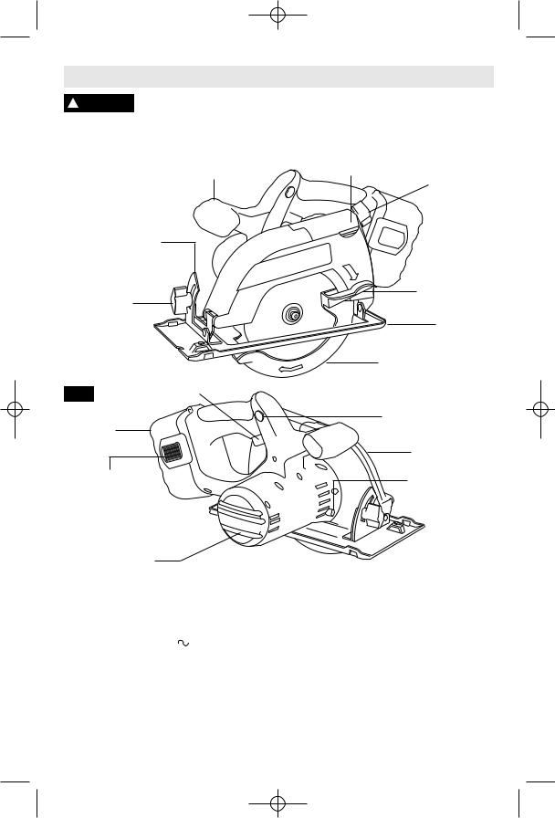
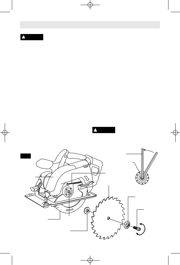
Functional Description and Specifications
Disconnect battery pack from tool or place the switch in the locked or ! WARNING off position before making any assembly, adjustments or changing
accessories. Such preventive safety measures reduce the risk of starting the tool accidentally.
AUXILIARY
HANDLE
Cordless
Circular Saws
CALIBRATED
BEVEL QUADRANT
BEVEL
ADJUSTMENT
KNOB
FIG. 1 |
TRIGGER |
BATTERY
PACK
BATTERY PACK
RELEASE TABS
BLADE WRENCH &


STORAGE AREA
VENTILATION
OPENINGS
DUST PORT
COVER DEPTH ADJUSTMENT
KNOB
LOWER
GUARD LIFT
LEVER
FOOT
LOWER
GUARD
SAFETY SWITCH
RELEASE
BUTTON
UPPER GUARD
LOCK
BUTTON
Model number |
1659 |
|
|
|
|
Voltage rating |
18 V |
|
|
|
|
|
|
|
|
||
No load speed |
n0 3,600/min |
||||
Charger |
BC003,4,6, & BC016 |
||||
|
BC130 & BC230 |
||||
Voltage rating |
120 V |
60 Hz |
|||
Battery pack |
BAT025 & BAT26 |
||||
|
BAT160 thru BAT189 |
||||
1661
14.4 V 

 n0 3,600/min
BC001-6 & BC016 BC130 & BC230 120 V  60 Hz
60 Hz
BAT040
BAT140 thru BAT159
Maximum Capacities |
|
Blade |
5-3/8" |
Depth of cut at 90° |
1-5/8" |
Depth of cut at 45° |
1-1/4" |
ATTENTION: Use only thin kerf blades designed for Cordless Circular Saws.
BC006 charger requires 12 V DC input
NOTE: ONLY USE CHARGERS LISTED ABOVE
For replacement blades we recommend Bosch Cordless Circular saw blades. Their thin kerf and tooth design deliver the best speed, quality of cut, and reduce battery drain. Use of standard blades will substantially affect the performance and reduce run-time.
-9-
BM 2610925945 6-05 6/10/05 10:30 AM Page 10
Assembly
ATTACHING THE BLADE |
Do not use wrenches with longer handles, |
||
Disconnect battery pack |
since it may lead to over tightening of the blade |
||
! WARNING from tool |
or place the |
stud. |
|
switch in the locked or off position before |
VARI-TORQUE CLUTCH |
||
making any assembly, adjustments or |
This clutching action is provided by the friction |
||
changing accessories. Such preventive |
of the OUTER WASHER against the BLADE |
||
safety measures reduce the risk of starting |
and permits the blade shaft to turn when the |
||
the tool accidentally. |
|
blade encounters excessive resistance. When |
|
1. Turn BLADE STUD with wrench provided |
the BLADE STUD is properly tightened (as |
||
clockwise and remove BLADE STUD and |
described in No. 5 of Attaching The Blade), the |
||
OUTER WASHER (Fig. 2). If the shaft moves |
blade will slip when it encounters excessive |
||
while attempting to loosen the blade stud press |
resistance, thus reducing saw’s tendency to |
||
the lock button (Fig. 1). |
|
KICKBACK. |
|
2. Retract the lower guard all the way up into |
One setting may not be sufficient for cutting all |
||
the upper guard. While retracting the lower |
materials. If excessive blade slippage occurs, |
||
guard, check operation and condition of the |
tighten the blade stud a fraction of a turn more |
||
LOWER GUARD SPRING. |
|
(less than 1/8 turn). OVERTIGHTENING THE |
|
3. Make sure the saw teeth and arrow on the |
BLADE STUD NULLIFIES THE EFFECTIVE- |
||
NESS OF THE CLUTCH. |
|||
blade point in the same direction as the arrow |
|||
|
|||
on the lower guard. |
|
DUST EXTRACTION |
|
4. Slide blade through slot in the foot and |
Your tool is equipped is with a dust port for dust |
||
mount it against the INNER WASHER on the |
and chip extraction. To use this feature, open |
||
shaft. Be sure the large diameter of the OUTER |
dust port cover and attach vacuum hose |
||
washer lays flush against the blade. |
(optional accessory) to the dust port, and |
||
5. Reinstall OUTER WASHER and tighten |
connect opposite end the hose to a shop |
||
vacuum cleaner. |
|||
BLADE STUD finger tight. The face of outer |
|||
! WARNING To prevent personal injury, |
|||
washer has marks on it that will help you |
|||
properly adjust the blade stud. Press lock |
always position vacuum |
||
button to lock shaft and TIGHTEN BLADE |
hose so that it does not interfere with the |
||
STUD COUNTER-CLOCKWISE ONE MARK |
lower guard, or the cutting operation at all |
||
ON BLADE WASHER WITH THE WRENCH |
settings. |
||
PROVIDED. |
|
|
|
FIG. 2 |
|
WRENCH |
|
|
|
||
|
|
MARK |
|
|
|
LOWER |
|
UPPER |
|
GUARD |
|
|
SPRING |
||
GUARD |
|
|
|
|
|
BLADE |
|
|
|
OUTER WASHER |
|
|
|
OUTER WASHER |
|
|
|
Large Diameter |
|
|
|
Faces Blade |
|
|
|
BLADE |
|
|
|
STUD |
|
LOWER |
BLADE |
TIGHTEN |
|
GUARD |
SHAFT |
||
|
|||
INNER WASHER
Large Diameter
Faces Blade
LOOSEN
-10-

BM 2610925945 6-05 6/10/05 10:30 AM Page 11
Operating Instructions
DEPTH ADJUSTMENT
Disconnect battery pack from tool. Loosen the depth adjustment knob located on the back side of the upper guard. Hold the foot down with one hand and raise or lower saw by the handle. Tighten knob at the depth setting
desired. Check desired depth (Fig. 3).
Not more than one tooth length of the blade should extend below the material to be cut, for minimum splintering (Fig. 4).
FIG. 3 |
FIG. 4 |
DEPTH
ADJUSTMENT
KNOB
BLADE
WRENCH &
STORAGE AREA
CALIBRATED DEPTH
BRACKET
ONE TOOTH LENGTH SHOULD PENETRATE WOOD FOR MINIMUM SPLINTERING
SAFETY SWITCH
The safety switch is designed to prevent accidental starts. To operate safety switch, press the release button with your thumb on either side of handle to disengage the lock, then pull the trigger (Fig. 5). When the trigger is released the button will engage the safety switch automatically, and the trigger will no longer operate. (See Switch & General Cuts on page 11.)
FIG. 5
SAFETY SWITCH
RELEASE
BUTTON
90° CUTTING ANGLE CHECK
Disconnect battery pack from tool. Set foot to maximum depth of cut setting. Loosen bevel adjustment knob, set to 0° on quadrant, retighten knob and check for 90° angle between the blade and bottom plane of foot with a square (Fig. 6). If adjustment is necessary, tilt foot to 45°, tighten bevel adjustment wing nut and bend "TAB" with an adjustable wrench or pliers (Fig. 7).
FIG. 6 |
FIG. 7 |
BEVEL
ADJUSTMENT
KNOB
FOOT 90°
90°
TRIGGER |
BLADE |
TAB |
-11-
BM 2610925945 6-05 6/10/05 10:30 AM Page 12
BEVEL ADJUSTMENT
Disconnect battery pack from tool. The foot can be adjusted up to 50° by loosening the bevel adjustment knob at the front of the saw. Align to desired angle on calibrated quadrant. Then tighten bevel adjustment knob (Fig. 8). Because of the increased amount of blade engagement in the work and decreased stability of the foot, blade binding may occur. Keep the saw steady and the foot firmly on the workpiece.
FIG. 8
QUADRANT
BEVEL
ADJUSTMENT
KNOB
LINE GUIDE
For a straight 90° cut, use right side of notch in the foot. For 45° bevel cuts, use the left side (Fig. 9). The cutting guide notch will give an approximate line of cut. Make sample cuts in scrap lumber to verify actual line of cut. This will be helpful because of the number of different blade types and thicknesses available. To ensure minimum splintering on the good side of the material to be cut, face the good side down.
90° |
45° |
VERTICAL |
BEVEL |
CUTS |
CUTS |
FIG. 9
SWITCH
To turn tool “ON”, squeeze the trigger switch. To turn the tool “OFF”, release the trigger switch, which is spring loaded and will return to the off position automatically.
Your saw should be running at full speed BEFORE starting the cut, and turned off only AFTER completing the cut. To increase switch life, do not turn switch on and off while cutting.
BRAKE
When the trigger is released it activates the electrical brake to stop the blade quickly. This feature is especially useful when making repetitive cuts.
GENERAL CUTS
Always hold the saw handle with one hand and the auxiliary handle or housing with the other.
Always make sure saw foot rests on portion of work surface that does not drop off.
! WARNING Always be sure either hand does not interfere
with the free movement of the lower guard.
Maintain a firm grip and operate the switch with a decisive action. Never force the saw. Use light and continuous pressure.
After completing a cut and ! WARNING the trigger has been
released, be aware of the necessary time it takes for the blade to come to a complete stop during coast down. Do not allow the saw to brush against your leg or side, since the lower guard is retractable, it could catch on your clothing and expose the blade. Be aware of the necessary blade exposures that exist in both the upper and lower guard areas.
When cutting is interrupted, to resume cutting: squeeze the trigger and allow the blade to reach full speed, re-enter the cut slowly and resume cutting.
When cutting across the grain, the fibers of the wood have a tendency to tear and lift. Advancing the saw slowly minimizes this effect. For a finished cut, a cross cut blade or miter blade is recommended.
-12-
BM 2610925945 6-05 6/10/05 10:30 AM Page 13
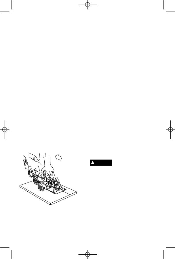
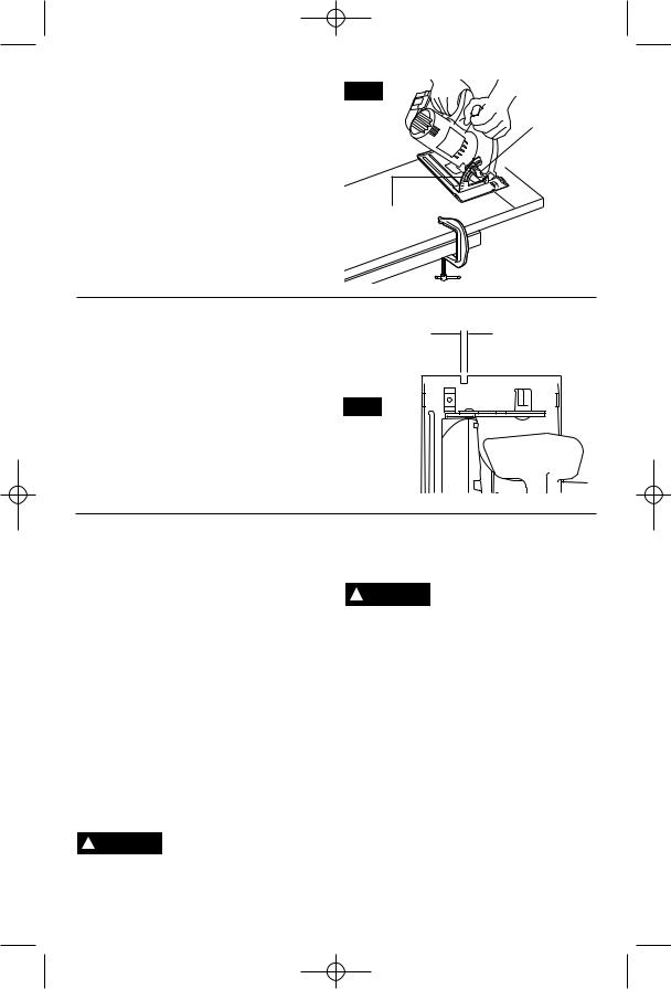
POCKET CUTS
Disconnect battery pack from tool before making adjustments. Set depth adjust-ment according to material to be cut. Tilt saw forward with cutting guide notch lined up with the line you’ve drawn. Raise the lower guard, using lift lever and hold the saw by the front and rear handles (Fig. 10).
With the blade just clearing the material to be cut, start the motor. Gradually lower the back end of saw using the front end of the foot as the hinge point. WARNING: As blade starts cutting the material, release the lower guard immediately. When the foot rests flat on the surface being cut, proceed cutting in forward direction to end of cut. WARNING: Allow blade to come to a complete stop before lifting the saw from cut. Also, never pull the saw backward since blade will climb out of the material and KICKBACK will occur. Turn saw around and finish the cut in the normal manner, sawing forward. If corners of your pocket cut are not completely cut through, use a jigsaw or hand saw to finish the corners.
FIG. 10
LOWER
GUARD
LIFT
LEVER
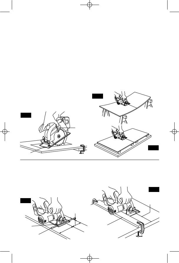
CUTTING LARGE SHEETS
Large sheets and long boards sag or bend, depending on support. If you attempt to cut without leveling and properly supporting the piece, the blade will tend to bind, causing KICKBACK and extra load on the motor (Fig. 11).
Support the panel or board close to the cut, as shown in (Fig. 12). Be sure to set the depth of the cut so that you cut through the sheet or board only and not the table or work bench. The two-by-fours used to raise and support the work should be positioned so that the broadest sides support the work and rest on the table or bench. Do not support the work with the narrow sides as this is an unsteady arrangement. If the sheet or board to be cut is too large for a table or work bench, use the supporting two-by-fours on the floor and secure.
FIG. 11
WRONG
FIG. 12
FOOT |
RIGHT |
RIP CUTS
The combination blade provided with your saw is for both cross cuts and rip cuts. Ripping is cutting lengthwise with the grain of the wood. Rip cuts are easy to do with a rip fence (Fig. 13). Rip Fence is available as an accessory (not included). To attach fence, insert fence through slots in foot to desired width as shown and secure with the knob.
FIG. 13
DESIRED
WIDTH
OF CUT
RIP BOARD GUIDE
When rip cutting large sheets, the rip fence may not allow the desired width of cut. Clamp or nail a straight piece of 1" (25 mm) lumber to the sheet as a guide (Fig. 14). Use the right side of the foot against the board guide.
FIG. 14
DESIRED
LINE
OF CUT
|
RIP |
|
KNOB |
BOARD |
|
GUIDE |
||
|
||
|
RIP |
|
|
FENCE |
-13-
BM 2610925945 6-05 6/10/05 10:30 AM Page 14
RELEASING AND INSERTING BATTERY PACK
Release battery pack from tool by pressing on both sides of the battery release tabs and pull downwards. Before inserting battery pack, remove protective cap from battery
pack. To insert battery, align battery and slide battery pack into tool until it locks into position. Do not force.
IMPORTANT CHARGING NOTES
1.The battery pack accepts only about 80% of its maximum capacity with its first few charge cycles. However, after the first few charge cycles, the battery will charge to full capacity.
2.The charger was designed to fast charge the battery only when the battery temperature is between 40˚F (4˚C) and 105˚F (41˚C).
3.A substantial drop in operating time per charge may mean that the battery pack is nearing the end of its life and should be replaced.
4.If you anticipate long periods (i.e. a month or more) of non-use of your tool, it is best to run your tool down until it is fully discharged before storing your battery pack. After a long period of storage, the capacity at first recharge will be lower. Normal capacity will be restored in two or three charge/discharge cycles.
Remember to unplug charger during storage period.
5.If battery does not charge properly:
a.Check for voltage at outlet by plugging in some other electrical device.
b.Check to see if outlet is connected to a light switch which turns power “off” when lights are turned off.
c.Check battery pack terminals for dirt. Clean with cotton swab and alcohol if necessary.
d.If you still do not get proper charging, take or send tool, battery pack and charger to your local Bosch Service Center. See “Tools, Electric” in the Yellow Pages for names and addresses.
Note: Use of chargers or battery packs not sold by Bosch will void the warranty.
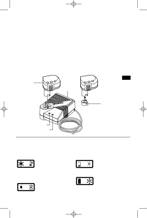
CHARGING BATTERY PACK (30 MINUTE SINGLE BAY-BC130)
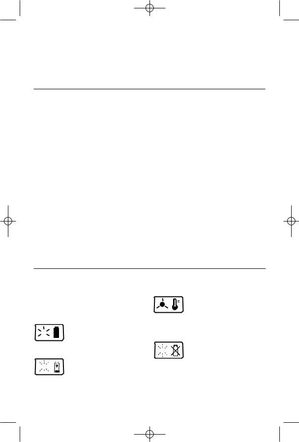
INDICATORS, SYMBOLS AND MEANING
If the indicator lights are “OFF”, the charger is not receiving power from power supply outlet.
If the green indicator light is
 “ON”, the charger is plugged in
  but the battery pack is not inserted, or the battery pack is fully charged
and is being trickle charged.
If the green indicator light is


 “BLINKING”, the battery pack is
  being fast-charged. Fastcharging will automatically stop when the
battery pack is fully charged.
If the red indicator light is “ON”,


 the battery pack is too hot or
  cold for fast-charging. The charger will switch to trickle charge, until a
suitable temperature is reached, at which time the charger will switch automatically to fast-charging.
If the red indicator light is


 “BLINKING”, the battery pack cannot accept a charge or the contacts of the charger or battery pack are
contaminated. Clean the contacts of the charger or battery pack only as directed in these operating instructions or those supplied with your tool or battery pack.
-14-
BM 2610925945 6-05 6/10/05 10:30 AM Page 15
Plug charger cord into your standard power outlet. Before inserting battery pack, remove protective cap, then insert battery pack into charger (Fig. 15).
The charger’s green indicator light will begin to “BLINK”. This indicates that the battery is receiving a fast charge. Fast-charging will automatically stop when the battery pack is fully charged.
When the indicator light stops “BLINKING” (and becomes a steady green light) fast charging is complete.
The battery pack may be used even though the light may still be blinking. The light may require more time to stop blinking depending on temperature. When you begin the charging process of the battery pack, a steady red light
could also mean the battery pack is too hot or too cold.
The purpose of the green light is to indicate that the battery pack is fast-charging. It does not indicate the exact point of full charge. The light will stop blinking in less time if the battery pack was not completely discharged.
When charging several batteries in sequence, the charge time may slightly increase.
When the battery pack is fully charged, unplug the charger (unless you're charging another battery pack) and slip the battery pack back into the tool.
To prevent fire or injury when batteries are not in tool or charger, always place protective cap onto end of battery pack.
FIG. 15
BATTERY
PACK
CHARGER
PROTECTIVE
CAP
RED LIGHT
GREEN LIGHT
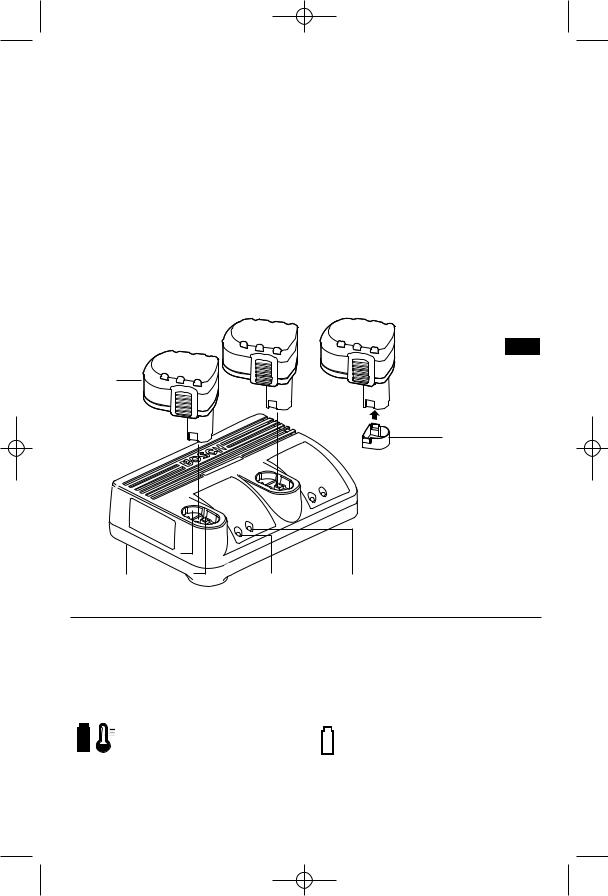
CHARGING BATTERY PACK (30 MINUTE DUAL BAY-BC230)
INDICATORS, SYMBOLS AND MEANING
If the indicator lights are “OFF”, the charger is not receiving power from power supply outlet.
If the red indicator light is
“ON”, the battery pack is too hot or cold for fast-charging.
The charger will switch to trickle charge, until a suitable temperature is reached, at which time the charger will switch automatically to fast-charging.
If the red indicator light is 


 “BLINKING”, the battery pack cannot accept a charge or the contacts of the charger or battery pack
are contaminated. Clean the contacts of the charger or battery pack only as directed in these operating instructions or those supplied with your tool or battery pack.
If the green indicator light is 


 “BLINKING”, the battery pack is being fast-charged. Fastcharging will automatically stop when the
battery pack is fully charged.
If the green indicator light is “ON”, the charger is plugged in but the battery pack is not
inserted, or the battery pack is fully charged and is being trickle charged.
-15-
BM 2610925945 6-05 6/10/05 10:30 AM Page 16
Plug charger cord into your standard power outlet. Before inserting battery pack, remove protective cap, then insert battery pack into charger (Fig. 16).
The charger’s green indicator light will begin to “BLINK”. This indicates that the battery is receiving a fast charge. Fast-charging will automatically stop when the battery pack is fully charged.
When the indicator light stops “BLINKING” (and becomes a steady green light) fast charging is complete.
The battery pack may be used even though the light may still be blinking. The light may require more time to stop blinking depending on temperature. When you begin the charging process of the battery pack, a
steady red light could also mean the battery pack is too hot or too cold.
The purpose of the green light is to indicate that the battery pack is fast-charging. It does not indicate the exact point of full charge. The light will stop blinking in less time if the battery pack was not completely discharged.
When charging several batteries in sequence, the charge time may slightly increase.
When the battery pack is fully charged, unplug the charger (unless you're charging another battery pack) and slip the battery pack back into the tool.
To prevent fire or injury when batteries are not in tool or charger, always place protective cap onto end of battery pack.
FIG. 16
BATTERY
PACK
PROTECTIVE
CAP
CHARGER |
RED LIGHT GREEN LIGHT |
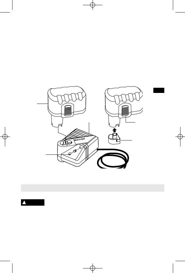
CHARGING BATTERY PACK (1 HOUR CHARGER)
INDICATORS, SYMBOLS AND MEANING
If the indicator lights are “OFF”, the charger is not receiving power from power supply outlet.
If the green indicator light is “ON”,

 the charger is plugged in but the battery pack is not inserted, or the battery pack is fully charged and is being
trickle charged, or the battery pack is too hot or cold for fast-charging. The charger will
switch to trickle charge, until a suitable temperature is reached, at which time the charger will switch automatically to fastcharging.
If the green indicator light is “BLINKING”, the battery pack is being fast-charged. Fast-charging
will automatically stop when the battery pack is fully charged.
-16-
BM 2610925945 6-05 6/10/05 10:30 AM Page 17
Plug charger cord into your standard power outlet. Before inserting battery pack, remove protective cap, then insert battery pack into charger (Fig. 17).
The charger’s green indicator will begin to “BLINK”. This indicates that the battery is receiving a fast charge. Fast-charging will automatically stop when the battery pack is fully charged.
When the indicator light stops “BLINKING” (and becomes a steady green light) fast charging is complete.
When you begin the charging process of the battery pack, a steady green light could also mean the battery pack is too hot or too cold.
The purpose of the light is to indicate that the battery pack is fast-charging. It does not indicate the exact point of full charge. The light will stop blinking in less time if the battery pack was not completely discharged.
When the battery pack is fully charged, unplug the charger (unless you're charging another battery pack) and slip the battery pack back into the tool handle (Fig.17).
To prevent fire or injury when batteries are not in tool or charger, always place protective cap onto end of battery pack.
FIG. 17
BATTERY
PACK
CHARGER |
BATTERY PACK |
|
RELEASE TABS |
PROTECTIVE
CAP
INDICATOR
LIGHT
Maintenance
Service
! WARNING NO USER SERVICEABLE PARTS INSIDE. Preventive
maintenance performed by unauthorized personnel may result in misplacing of internal wires and components which could cause serious hazard. We recommend that all tool service be performed by a Bosch Factory Service Center or Authorized Bosch Service Station. SERVICEMEN: Disconnect tool and/or charger from power source before servicing.
BATTERIES
Be alert for battery packs that are nearing their end of life. If you notice decreased tool performance or significantly shorter running time between charges then it is time to replace the battery pack. Failure to do so can cause the tool to operate improperly or damage the charger.
Long term battery storage should be in the discharged state. Battery packs last longer and re-charge better when they are stored discharged. Remember to fully re-
-17-
 Loading...