


Before use - Read this instruction manual.
Lisez attentivement la présente notice avant l'emploi.
Lea estas instrucciones de manejo antes de la utilización del aparato.
BM 2610909755 7/01 |
1 |
7/26/01, 12:03 PM |

Fig. 1
1
2
3
8 |
4 |
|
5 |
|
6 |

 7 9
7 9 

(Model 1608LX Pictured) (Modèle 1608LX illustré) (Modelo 1608LX ilustrado)
2
BM 2610909755 7/01 |
2 |
7/26/01, 12:03 PM |
Product Data - Trim Router
Base dimensions |
3.7" x 2.8" (95mm x 71mm) |
Collet capacity |
1/4" max. |
Bit diameter |
1" max. |
(NOTE: This tool is designed for use with alternating current (AC) only.)
Accessory Listing
*STANDARD EQUIPMENT—ALL MODELS
|
1608M |
1608 |
1608LX |
1608T |
1608U |
1609A |
1609AK |
1609AKX |
Steel Case |
|
|
|
|
|
|
* |
* |
650 Watt Trim Motor |
* |
* |
* |
* |
* |
* |
* |
* |
Wrench |
2pcs |
2pcs |
2pcs |
2pcs |
2pcs |
1pc |
2pcs |
2pcs |
Trimmer Base |
|
* |
* |
|
|
|
* |
* |
Laminate Trim Guide |
|
|
|
|
|
|
* |
|
Deluxe Laminate |
|
|
* |
|
|
|
|
* |
Trim Guide |
|
|
|
|
|
|
|
|
Tilt Base |
|
|
|
* |
|
|
* |
* |
Offset Base |
|
|
|
|
|
* |
* |
* |
Underscribe Base |
|
|
|
|
* |
|
|
* |
4mm Hex Key |
|
|
|
|
* |
* |
* |
* |
3mm Hex Key |
|
|
|
|
* |
|
|
* |
1/4 Collet |
* |
* |
* |
* |
* |
|
* |
* |
Collet Nut |
* |
* |
* |
* |
* |
|
* |
* |
Carbide Tipped Bit |
|
|
|
|
* |
|
|
* |
Toothed Belt Pulley |
|
|
|
|
|
* |
* |
* |
Trim Router Components
1. |
Ventilation openings |
11. |
Adjusting screw - depth of cut |
2. |
Wrench slot |
12. |
Adjusting knob - trim guide |
3. |
Slide "ON/OFF" switch |
13. |
Locking screw - trim guide |
4. |
Motor clamping ring |
14. |
Combination Wrench |
5. |
Collet nut |
15. |
Toothed Belt Pulley |
6. |
Base assembly |
16. |
Offset Base Assembly |
7. |
Sub-base |
17. |
Toothed Belt |
8. |
Clamping ring screw |
18. |
Depth Locking Screw |
9. |
Trim guide assembly |
19. |
Slotted Adjusting Gear |
10. |
Locking knob - depth of cut |
20. |
Wing Nuts |
(NOTE: components not illustrated on page 2 are illustrated elsewhere in this manual)
3
BM 2610909755 7/01 |
3 |
7/26/01, 12:03 PM |

WARNING! “READ ALL INSTRUCTIONS”. Failure to follow the SAFETY RULES identified by the BULLET (•) symbols listed BELOW and other safety precautions, may result in serious personal injury. Keep these operating instructions with this product.
GENERAL SAFETY RULES for all Power Tools
Work Area
•KEEP WORK AREAS CLEAN. Cluttered areas and benches invite accidents.
•AVOID DANGEROUS ENVIRONMENT. Don’t use power tools in damp or wet locations. Do not expose power tools to rain. Keep work area well lit.
•AVOID GASEOUS AREAS. Do not operate portable electric tools in explosive atmospheres in presence of flammable liquids or gases. Motors in these tools normally spark, and the sparks might ignite fumes.
•KEEP CHILDREN AWAY. Do not let visitors contact tool or extension cord. All visitors should be kept away from work areas.
Personal Safety
•GUARD AGAINST ELECTRIC SHOCK. Prevent body contact with grounded surfaces such as pipes, radiators, ranges and refrigerator enclosures. Rubber gloves and non-skid footwear are recommended when working outdoors, where damp or wet ground may be encountered. A Ground Fault Circuit Interrupter protected power line must be used for these conditions.
•DRESS PROPERLY. Do not wear loose clothing or jewelry. They can be caught in moving parts. Wear protective hair covering to contain long hair.
•USE SAFETY EQUIPMENT. WEAR SAFETY GOGGLES or glasses with side shields. Wear hearing protection during extended use of power tools and dust mask for dusty operations.
•STAY ALERT. USE COMMON SENSE. Watch what you are doing. Do not operate tool when you are tired or under influence of drugs.
•REMOVE ADJUSTING KEYS AND WRENCHES. Form habit of checking to see that keys and adjusting wrenches are removed from tool before turning it on.
•AVOID ACCIDENTAL STARTING. Don’t carry plugged in tool with finger on switch. Be sure the switch is OFF before being plugged in.
•DON’T OVERREACH. Keep proper footing and balance at all times.
•BEFORE CONNECTING THE TOOL to a
4
power supply (receptacle, outlet, etc.) be sure the voltage supplied is the same as that specified on the tool’s nameplate. A power supply with voltage greater than that specified for the tool can result in serious injury to the user—as well as damage to the tool. If in doubt, DO NOT PLUG IN THE TOOL. Using a power supply with voltage less than the nameplate rating is harmful to the motor.
“Volts AC” designated tools are for Alternating Current 50-60 Hz only. “Volts DC” designated tools are for Direct Current. Do not use AC designated tools with DC power supply. Do not use electronic speed controlled tools with DC power supply.
Tool Use and Care
•DON’T FORCE TOOL. It will do the job better and safer at the rate for which it was designed.
•USE RIGHT TOOL. Don’t force small tool or attachment to do the job of a heavy-duty tool. Don’t use tool for purpose not intended—for example; don’t use a circular saw for cutting tree limbs or logs.
•SECURE WORK. Use clamps or a vise to hold work. It’s safer than using your hand and it frees both hands to operate the tool.
•DON’T ABUSE CORD. Never carry tool by cord or yank it to disconnect from receptacle. Keep cord from heat, oil, and sharp edges. Always keep cord away from the spinning blade, bits or any other moving part while the tool is in use.
•OUTDOOR USE EXTENSION CORDS. When tool is used outdoors, use only extension cords suitable for use outdoors and marked with suffix W-A (for UL), or W (for CSA). Refer to section “Extension Cords”, for proper cord use.
•DISCONNECT TOOLS. When not in use, before servicing, or when changing blades, bits, cutters, etc.
•STORE IDLE TOOLS. When not in use, tools should be stored in dry, high or locked up place - out of the reach of children.
•DO NOT ALTER OR MISUSE TOOL. These tools are precision built. Any alterations or modifications not specified is misuse and may result in a dangerous condition.
•THE USE OF ANY ACCESSORIES not specified in this manual may create a hazard.
•MAINTAIN TOOLS WITH CARE. Keep tools sharp and clean for better and safer performance. Follow instructions for lubricating and changing accessories. Inspect tool cords periodically and if damaged, have repaired by au-
BM 2610909755 7/01 |
4 |
7/26/01, 12:03 PM |
thorized service facility. Inspect extension cords periodically and replace if damaged. Keep handles dry, clean and free from oil and grease.
•CHECK DAMAGED PARTS. Before further use of the tool, a guard or other part that is damaged should be carefully checked to determine that it will operate properly and perform its intended function. Check for alignment of moving parts, binding of moving parts, breakage of parts, mounting, and any other conditions that may affect its operation. A guard or other part that is damaged should be promptly and properly repaired or replaced. Have defective switches replaced. Do not use tool if switch does not turn it on or off.
•ALL REPAIRS, ELECTRICAL OR MECHANICAL, should be attempted only by trained repairmen. Contact the nearest Bosch Factory Service Center, or Bosch Authorized Service Center or other competent repair center. Use only Bosch replacement parts, any other may create a hazard
Safety Rules for Trim Router
•Always wear safety goggles. If trimmer has a removable chip deflector, keep it in place when routing.
•Never use dull or damaged bits. Handle bits with care.
•Always make sure the workpiece is free from nails and other foreign objects which can cause the bit and trimmer to jump and damage the bit.
•Be sure that the bit is installed according to the procedure described in this manual. Check all settings and adjustments before making a cut. An incorrectly installed bit or loose setting could cause an accident or injury. Always disconnect the power cord before making adjustments or changing bits.
•Do not make adjustments while the tool is running.
•Never hold the workpiece in one hand and the trimmer in other when in use. Always clamp the material and hold the trimmer securely with both hands.
•Never start the trimmer when the bit is engaged in the material. The bit’s cutting edge may grab the material causing the trimmer to get out of control. Always hold the trimmer with two hands during start-up. The reaction torque of the motor can cause the trimmer to twist.
•When turning the trimmer "ON", be aware that the bit is protruding below the base. Keep hands away from this area.
5
•Do not cut or rout into existing walls, around any fixture or in a blind area which may have electrical wiring, as the bit could conduct electricity to the tool, creating a hazard for the operator.
•The trimmer should always be used with its base flat on the material being cut. For better control and accuracy of cut, guide the trimmer with both hands. Use hand positions most comfortable and giving best control for your job.
•Never use bits that have a cutting diameter greater than the opening in the base.
•The direction of feeding the trimmer into the material is very important and it relates to the direction of bit rotation. When viewing the trimmer from the top, the bit rotates clockwise. When the trimmer is located between your body and the material, the feed direction must be to the right. If the material is located between your body and the trimmer, then the feed direction must be to the left. Feeding the trimmer in the wrong direction causes the cutting edge of the bit to climb out of the work and pull the trimmer in the direction of this feed.
•Never touch the bit or other moving part during use. After use the bit is too hot to be touched by bare hands.
•Be sure that the bit has come to a complete stop before you put the trimmer down. This will reduce the chance of unintentional contact with the bit.
•When using the tool for laminate trimming, keep the laminate overhang small. Do no allow too much laminate to overhang when cutting the laminate parts to size. When the overhang is too great, it makes the trimmer more difficult to control. If the laminate overhangs the workpiece by more than 2", use an overhang bit to reduce the amount of material before actually trimming the laminate to desired size.
WARNING! Some dust created by power sanding, sawing, grinding, drilling, and other construction activities contains chemicals known to cause
cancer, birth defects or other reproductive harm. Some examples of these
chemicals are:
•Lead from lead-based paints,
•Crystalline silica from bricks and cement and other masonry products, and
•Arsenic and chromium from chemically treated lumber.
Your risk from these exposures varies, depending on how often you do this type of work. To reduce your exposure to these chemicals: work
BM 2610909755 7/01 |
5 |
7/26/01, 12:03 PM |
in a well ventilated area, and work with approved safety equipment, such as those dust masks that are specially designed to filter out microscopic particles.
Double Insulated Tools
• Double Insulation 


 is a design concept used in electric power tools which eliminates the need for the three wire grounded power cord and grounded power supply system. It is a recognized and approved system by Underwriter’s Laboratories, CSA and Federal OSHA authorities.
IMPORTANT: Servicing of a tool with double insulation requires care and knowledge of the system and should be performed only by a qualified service technician. WHEN SERVICE IS REQUIRED USE ONLY IDENTICAL REPLACEMENT PARTS.
POLARIZED PLUGS: If your tool is equipped with a polarized plug (one blade is wider than the other), this plug will fit in a polarized outlet only one way. If the plug does not fit fully in the outlet, reverse the plug. If it still does not fit, contact a qualified electrician to install the proper outlet. To reduce the risk of electric shock do not change the plug in any way.
Extension Cords
• Replace damaged cords immediately. Use of damaged cords can shock, burn or electrocute.
•If an extension cord is necessary, a cord with adequate size conductors should be used to prevent excessive voltage drop, loss of power or overheating. The table below shows the correct size to use, depending on cord length and amperage rating on the tool’s nameplate. If in doubt, use the next heavier gauge. Always use U.L. and CSA listed extension cords.
Ampere Rating (shown on nameplate)
|
|
0- |
2.1- |
3.5- |
5.1- |
7.1- |
12.1- |
|
|
|
2.0 |
3.4 |
5.0 |
7.0 |
|
12.0 |
16.0 |
Length |
|
|
|
|
|
|
|
|
25' |
18 |
18 |
18 |
18 |
|
16 |
14 |
|
|
|
|||||||
|
50' |
18 |
18 |
16 |
16 |
|
14 |
12 |
Cord |
75' |
18 |
18 |
16 |
14 |
|
12 |
10 |
100' |
18 |
16 |
14 |
12 |
|
10 |
|
|
|
|
|
||||||
|
150' |
16 |
14 |
12 |
12 |
Wire Gauge |
||
|
|
|
|
|
|
|
|
|
Note: Thesmallerthegaugenumber,thelarger
the wire is in the cord.
"SAVE THESE INSTRUCTIONS"
Operating the Tool
Slide "ON/OFF" Switch
This tool is switched "ON" by the slide switch located on the front of the motor housing. TO TURN THE TOOL "ON" slide the switch button to the right or "I" position.
TO TURN THE TOOL "OFF" slide the switch button to the left or "0" position. WARNING! Hold the tool with both hands while starting the tool, since torque from the motor can cause the tool to twist.
All Models Except Model 1609A
Inserting and Removing Bits
WARNING! Always disconnect tool from the power source before installing bits, accessories, or making any adjustments.
If the base is installed, you may remove it to completely expose the collet assembly. The motor may be placed on its side or flat top surface when changing bits.
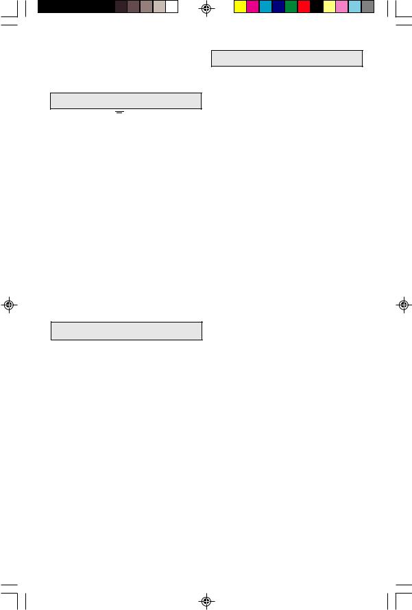
Insert the small end of one of the wrenches provided into slot 2 in the motor. The wrench is designed to turn and lock the armature, but it may be necessary to turn the armature shaft from the collet end to position the shaft in the wrench. The wrench MUST be fully inserted to the line stamped on the wrench before loosening or tightening the collet nut. Damage to the armature shaft is possible if the wrench is not fully inserted.
Fig. 2 |
|
Fig. 3 |
|
|
|
With the shaft firmly locked, turn collet nut 5 in a counterclockwise direction with the other wrench provided. Insert the shank of the router bit as far as it will go, back it out until the cutters are 1/8" to 1/4" from the collet nut, and firmly tighten the nut in a clockwise direction to secure the bit. Remove both wrenches from the tool and re-attach base or any accessories before connecting tool to the power source. Reverse the above procedure to remove the bit, and if it does not slide out easily, tap the collet nut sharply with the wrench to free it. NEVER strike the bit.
6
BM 2610909755 7/01 |
6 |
7/26/01, 12:03 PM |
Model 1609A Only
Insert the 4mm hex wrench supplied into the hole in the top of the offset base to hold the spindle in position, and loosen the collet in a counterclockwise direction with one of the combination wrenches supplied. Insert a laminate trim bit into the collet as far as it will go, and back out slightly until the cutters are 1/8" to 1/4" away from the collet. Holding the spindle firmly with the 4mm hex wrench, tighten the collet in a clockwise direction with the combination wrench to firmly grip the bit.
Fig. 4
Wrench 
To remove bit, use the wrenches as described above, and turn the collet in a counterclockwise direction until the bit can be pulled out. Note that the collet is self-extracting; it is NOT necessary to strike the collet to free the bit.
CAUTION! The minimum insertion of the bit shank is 5/8" to ensure proper gripping and minimize bit run-out.
Collet Care
With the router bit removed, continue to turn the collet or collet nut counterclockwise until it is free of the spindle and the collet can be removed. To assure a firm grip, occasionally blow out the collet with compressed air and clean the taper in the spindle shaft with a tissue or fine brush.
After cleaning, reinsert the collet and lightly thread in place. To avoid damage, NEVER tighten the collet or collet nut unless a bit is inserted. Replace worn or damaged collets immediately.
Assembling Motor to Base All Models Except Model 1609A
Insert router motor into clamping ring 4. Rotate motor to the desired position, and tighten clamping ring screw 8 with a screwdriver. Be sure clamping ring holds motor firmly before turning tool "ON ", but do not overtighten the ring.
Model 1609A Only
Remove collet and nut (if fitted) from motor spindle as described earlier. Lock the armature shaft with the combination wrench 14 furnished, and screw the toothed pulley 15 in
Fig. 5 |
15 |
14
place with a screwdriver. Remove the combination wrench, and with the clamping ring loosened, slide the offset base assembly 16 into place on the motor as far as it will go.
Fig. 6 |
16 |
17
As the base is installed, it is necessary to guide the toothed belt 17 over the pulley by using a screwdriver inserted through the U-shaped hole in the sub-base. Position the motor in the base in the most comfortable position to suit the operator, and tighten the clamping ring firmly. Do not overtighten.
Depth Adjustment
Model 1608, 1608LX Only
With the motor clamped in the base and the bit installed, loosen knob 10 and raise or lower the motor and cutter with adjusting screw 11 until the desired amount of bit is exposed. Tighten knob 10 and make a test cut in scrap material.
Fig. 7
11
10
Repeat this procedure until the desired depth of cut is achieved.
7
BM 2610909755 7/01 |
7 |
7/26/01, 12:03 PM |
Laminate Trim Guide
Unpiloted laminate trim bits require the use of a trim guide which may be fitted to models 1608, 1608LX, or 1609A. Mount the guide 9 to
Fig. 8 |
9 |
9 |
|
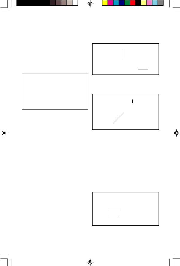
the bottom of the base in either pair of holes (1609A has one pair of holes) with the screws provided, and be sure the bit clears the trim guide by at least 1/16" (1.5 mm) to avoid damage. The horizontal position of the guide determines the amount of material removed by the bit. To adjust, loosen screw 13 and turn adjuster 12 to move the guide in or out. Tighten screw 13, and make a trial cut to check the
Fig. 9
13 12
setting and readjust as necessary. For making straight or bevel cuts, align the tip of the guide with the cutting edge of the bit to produce the desired amount of cutter exposure that will trim the laminate flush or create the desired bevel.
Fig. 11 |
19 |
achieved. Do not overtighten.
Model 1608T has an angular adjustment range of 75 degrees—45 degrees in one direction, and 30 degrees in the other. To set the angle, loosen the wing nuts 20 on either side of the
Fig. 12
20
base, tilt motor to the desired angle, and retighten the wing nuts. Be careful not to overtighten, or the base may be damaged.
When tilted, model 1608T will trim laminated tops up to a vertical backsplash or on irregular corners. Use a suitable self-piloted bit such as Bosch, and guide the trimmer as shown in Figure 13.
Fig. 13
Refer to instruction sheet included with deluxe trim guide (1608LX, 1609KX) for additional adjustments required for that guide.
1608T
With the motor fastened tightly in the clamping ring and a bit installed, loosen the depth locking screw 18 with a screwdriver approximately 1/4 turn. Raise or lower the base by turning the slotted gear 19, and retighten screw 18 firmly when the desired adjustment is
Fig. 10 |
18 |
Underscribe Trimmer—Model 1608U
The underscribe trimmer is designed to cut plastic laminates when creating joints between pieces of such material. Properly adjusted, the router will produce very accurate seams between adjacent sections of the laminated surface.
To install the underscribe base insert the bit into the collet as described earlier in this manual. Slide the clamping ring of the base onto the motor's lower bearing housing as far as it will go, and carefully tighten the clamp ring screw. Now adjust the bit until the tip just enters the machined recess in the aluminum plate of the underscribe guide. Your tool is now assembled, and ready to make a test cut in some surplus material before beginning work.
8
BM 2610909755 7/01 |
8 |
7/26/01, 12:03 PM |

To create a joint, contact cement should be applied to the core material and the plastic laminate, and one piece of laminate should be fastened to the core with the other overlapping it by about 3/4". The fixed piece must have a clean, straight edge as it will serve as a guide for the underscribe base to follow. The overlapping sheet of laminate will then pass over the aluminum plate and be cut to the proper length by the router bit. (See Figure 14). This
Fig. 14
accurate system makes it a perfect tool for joining laminate on stile and rail constructions, circular or curved edges, and many other surfaces. Because the cutter will generate chips, it is necessary to keep the laminate pressed down tightly near the seam to keep these chips from getting into the joint—this is especially important on larger pieces of material. It is also necessary to keep steady pressure on the tool so that the guiding edge of the base remains in contact with the fixed piece of laminate throughout the operation. (See Figure 15). This is especially important at the beginning and end of a cut.
Fig. 15
An eccentric adjuster is fitted to the aluminum plate and if necessary, can be adjusted with the pin wrench provided, after loosening the two screws which mount the aluminum plate. To make the joint tighter, turn the eccentric clockwise. For a looser joint, turn the eccentric counterclockwise, as viewed from under the base (see Figure 16). It is advisable to make some test cuts on scrap material to determine if adjustment is required before beginning work, and to be certain that the screws are re-tight- ened after adjusting the eccentric. Once this is done, no further adjustment should be required.
Fig. 16
Note that the base receives a preliminary adjustment at the factory, but will generally need to be "fine tuned" by the user to produce a perfect seam.
Offset Trimmer
Model 1609A
Offset trimmer 1609A is primarily used for trimming laminate in confined areas such as backsplashes, corners, or other locations inaccessible to the standard trim bases (see Fig 17). Piloted bits may be used, or the laminate trim guides may be fitted for use with unpiloted bits. Note that the offset base is designed for these specialized laminate trimming applications, and is not suitable for heavy stock removal or continuous service.
Using Self-Piloted Bits
Self-piloted bits have an integral round tip or ball bearing which rides against the work surface above or below the cutters to control horizontal cutting depth. When using these bits, the trim guide is not required, and it is only necessary to adjust the cutting depth to allow the pilot to ride on the work surface. When guiding against a laminated surface, use wax or other lubricant and do not apply excess pressure or the piloted end may mar the work. Bearing pilots must be kept clean and free of adhesive or other residue. Router bit bearings are sealed and permanently lubricated, and should be replaced when they no longer turn freely to avoid damaging the work surface.
Templet Guides
Your Bosch trim router Model 1608 will accept optional Bosch templet guides for pattern and other fixture work. To install a guide, remove the sub-base 7, insert the desired templet guide into the sub-base recess, and reinstall the sub-base. (Templet guide screws are not used - the sub-base holds the guide in place). See your Bosch dealer for templet guides and other accessories.
9
BM 2610909755 7/01 |
9 |
7/26/01, 12:03 PM |
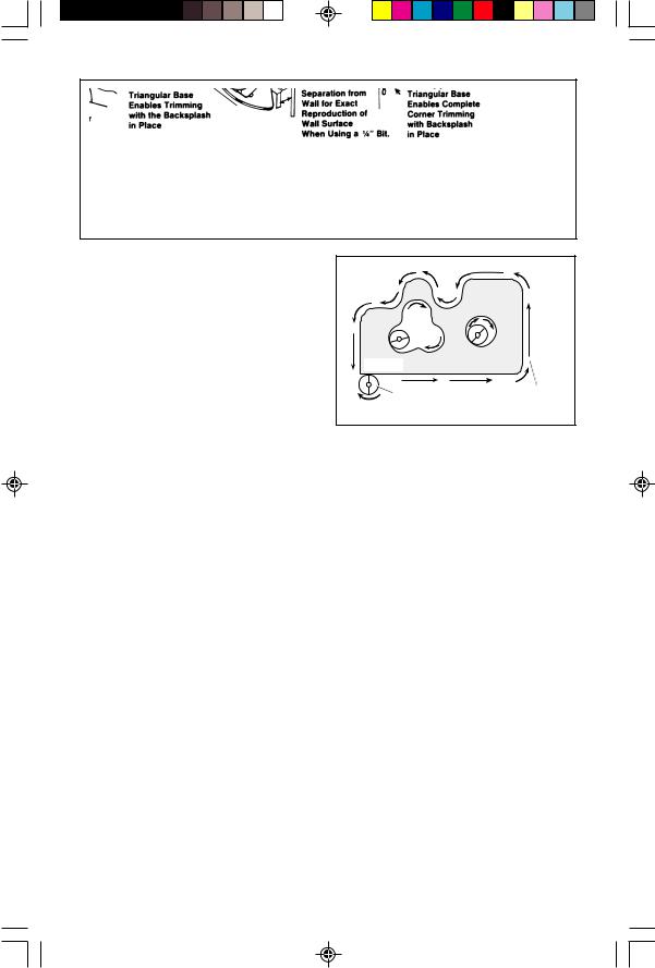
Fig. 17
WARNING! Use of any accessory not specified in this manual or the BOSCH catalog for use with this tool may create a hazard.
Trimming Tips
Your Bosch trim router is designed to trim laminates, phenolics, or other materials which have been bonded to a substrate and overhang by about 1/8" (3 mm). It is also handy for light edge forming, grooving, and sign making with 1/4" shank bits. Be sure the workpiece is secure, and clamp it in place if necessary. With the tool properly assembled and adjusted, be certain that the switch is in the “OFF” position, and connect to the power source. Grasp the motor housing firmly to resist starting torque, and slide switch 3 to the “ON” position. With the motor running at full speed, place the base of the trimmer on the work surface and feed the bit with a smooth steady motion into the material to be cut. The correct relationship between the direction of bit or cutter rotation and router feed is shown in Fig 18; feed in this direction or chatter will result.
Fig. 18 |
|
WORK |
|
CUTTER |
DIRECTION |
|
OF FEED |
Support the router on the long edge of the base whenever possible for maximum stability. At the completion of the cut, slide switch to the “OFF” position and allow the bit to come to a complete stop before setting the tool down. When using edge forming bits, it may be necessary to make the cut in more than one pass with progressively deeper settings to avoid overloading the motor. If the bit cuts freely and the motor does not slow down, the cutting depth is generally correct.
10
BM 2610909755 7/01 |
10 |
7/26/01, 12:03 PM |
Maintenance and Service
WARNING! Preventive maintenance performed by unauthorized personnel may result in misplacing of internal wires and components which could cause serious hazard. We recommend that all tool service be performed at a Bosch Factory Service Center.
Tool Lubrication
Your Bosch tool has been properly lubricated and is ready for use. We recommend, that tools with gears be regreased with a special gear lubricant every time the brushes are changed.
Carbon Brushes
The brushes and commutator in your Bosch tool have been engineered for many hours of dependable service. To maintain peak efficiency of the motor, we recommend that every two to six months the brushes be examined. Only genuine Bosch replacement brushes specially designed for your tool should be used.
Bearings
After about 300-400 hours of operation, or at every second brush change, the bearings should be replaced at a Bosch Factory Service Center. Bearings which become noisy (due to heavy load or very abrasive material cutting) should be replaced at once to avoid overheating and motor failure.
Cleaning
WARNING! To avoid accidents, always disconnect the tool from the power supply before cleaning or performing any maintenance. The tool may be cleaned most effectively with compressed air. Always wear safety goggles when cleaning tools with compressed air.
Ventilation openings and switch levers must be kept clean and free of foreign matter. Do not attempt to clean by inserting pointed objects through openings.
CAUTION! Certain cleaning agents and solvents damage plastic parts. Some of these are: gasoline, carbon tetrachloride, chlorinated cleaning solvents, ammonia and household detergents that contain ammonia.
NOTES:
11
BM 2610909755 7/01 |
11 |
7/26/01, 12:03 PM |
 Loading...