


Power Intercom Systems
Models PI35A & SI35A
Installation & Operation Guide
© 1997 Bogen Communications, Inc. 50 Spring St., Ramsey, NJ 07446
All rights are reserved. No part of this document may be photocopied, reproduced, or translated to another language without the prior written consent of Bogen Communications, Inc.
Notice: The information contained in this document is subject to change without notice and should not be construed as a commitment by Bogen Communications, Inc.
Bogen Communications, Inc. assumes no responsibility for any errors that may appear in this document nor does it make expressed or implied warranty of any kind with regard to this material, including, but not limited to, the implied warranties of merchantability and fitness for a particular purpose.
Bogen Communications, Inc. shall not be liable for incidental or consequential damages in connection with, or arising out of the furnishing, performance, or use of this document and the equipment which is describes.
WARNING
The Warning label calls attention to a procedure, practice, or the like, which, if not correctly performed or adhered to, could result in damage to the unit or personal injury. Do not proceed beyond a warning label until the indicated conditions are fully understood and met.
Publication No. 54-5034-01r2 0003
Printed in USA
2
Contents
Unpacking . . . . . . . . . . . . . . . . . . . . . . . . . . . . . . . . . . . . . . . . . . . . . . . . . . .4 Wiring & Grounding Precautions . . . . . . . . . . . . . . . . . . . . . . . . . . . . . . . . . .4 Auxiliary Power Receptacle . . . . . . . . . . . . . . . . . . . . . . . . . . . . . . . . . . . . . .4 Maintenance & Service . . . . . . . . . . . . . . . . . . . . . . . . . . . . . . . . . . . . . . . . .4 Introduction . . . . . . . . . . . . . . . . . . . . . . . . . . . . . . . . . . . . . . . . . . . . . . . . . .5
Description . . . . . . . . . . . . . . . . . . . . . . . . . . . . . . . . . . . . . . . . . . . . . . . . .5 Features . . . . . . . . . . . . . . . . . . . . . . . . . . . . . . . . . . . . . . . . . . . . . . . . . . .5 MCP35A Control Panel . . . . . . . . . . . . . . . . . . . . . . . . . . . . . . . . . . . . . . . .6 SBA225 Speaker Selector Panel . . . . . . . . . . . . . . . . . . . . . . . . . . . . . . . . .8
Basic System Operation . . . . . . . . . . . . . . . . . . . . . . . . . . . . . . . . . . . . . . . .9
Communicating With a Selected Speaker(s) . . . . . . . . . . . . . . . . . . . . . . . .9 Distributing Audio to Rooms . . . . . . . . . . . . . . . . . . . . . . . . . . . . . . . . . . . .9 Adjusting Program Level to Rooms . . . . . . . . . . . . . . . . . . . . . . . . . . . . . . .9 To Make an All-Rooms Announcement . . . . . . . . . . . . . . . . . . . . . . . . . . . .9 To Make an Emergency Announcement . . . . . . . . . . . . . . . . . . . . . . . . . . . .9
Basic System Hook-Up . . . . . . . . . . . . . . . . . . . . . . . . . . . . . . . . . . . . . . . .10
4-Wire Speaker Connections to the SBA225 . . . . . . . . . . . . . . . . . . . . . . .10 Call-In Switches . . . . . . . . . . . . . . . . . . . . . . . . . . . . . . . . . . . . . . . . . . . . .11 Voice Call-In Feature . . . . . . . . . . . . . . . . . . . . . . . . . . . . . . . . . . . . . . . . .11 Voice Call-In Wiring . . . . . . . . . . . . . . . . . . . . . . . . . . . . . . . . . . . . . . . . . .11 Speakers and Speaker Wiring . . . . . . . . . . . . . . . . . . . . . . . . . . . . . . . . . .12 Time Tones . . . . . . . . . . . . . . . . . . . . . . . . . . . . . . . . . . . . . . . . . . . . . . . .12
Advanced Hook-Ups . . . . . . . . . . . . . . . . . . . . . . . . . . . . . . . . . . . . . . . . . .13
External Emergency Mic . . . . . . . . . . . . . . . . . . . . . . . . . . . . . . . . . . . . . .13 Emergency Telco Page . . . . . . . . . . . . . . . . . . . . . . . . . . . . . . . . . . . . . . .13 External Booster Amp . . . . . . . . . . . . . . . . . . . . . . . . . . . . . . . . . . . . . . . .15 TWK351 Wire Converter . . . . . . . . . . . . . . . . . . . . . . . . . . . . . . . . . . . . . .16 SCR25A Call-In Module . . . . . . . . . . . . . . . . . . . . . . . . . . . . . . . . . . . . . . .17 CA17 Call-In Switch . . . . . . . . . . . . . . . . . . . . . . . . . . . . . . . . . . . . . . . . .17
SI35A Model Option Enhancements . . . . . . . . . . . . . . . . . . . . . . . . . . . . . .18 Special Adjustments . . . . . . . . . . . . . . . . . . . . . . . . . . . . . . . . . . . . . . . . . .19 Troubleshooting Guide . . . . . . . . . . . . . . . . . . . . . . . . . . . . . . . . . . . . . . . .21 System Specifications . . . . . . . . . . . . . . . . . . . . . . . . . . . . . . . . . . . . . . . . .22 Accessory Equipment . . . . . . . . . . . . . . . . . . . . . . . . . . . . . . . . . . . . . . . . .22
3
Unpacking
Your Bogen equipment was carefully checked before leaving the factory; inspect the shipping container and unit closely for improper handling. If the unit has been damaged, make an immediate claim to the distributor from whom it was purchased. If the unit was shipped directly to you, save all shipping materials and notify the carrier immediately and place a claim.
Wiring and Grounding Precautions
The MCP35A master control panel of the PI and SI products operates from a 120V 60Hz AC source and consumes approximately 100 watts. The AC line cord is terminated in a three-prong plug, and should be plugged into an appropriate three-wire grounded outlet. It is important that the unit be properly grounded. Three-prong pigtail adapters may be used only if the ground lug is properly grounded.
Auxiliary Power Receptacle
An 840-watt, three-wire grounded outlet is provided on the rear panel for power auxiliary equipment. Equipment connected to this outlet will be grounded only if the MCP35A control panel is properly grounded.
Maintenance & Service
Caution
There are no user-serviceable parts within the unit. Have all internal servicing performed by a qualified technician. The warranty will become void if repairs are made by other than the Bogen Service Department or an authorized service agency.
Our Applications Engineering Department is available to help you troubleshoot problems with your Bogen equipment. Engineers are available from 8:30AM to 8:00PM Eastern Standard Time. Phone (201) 934-8500, extension 2242.
Service can be obtained from our factory service department. No merchandise may be returned for repair without prior written authorization. Please contact our factory service department at 1-800-999-2809 for a RA number. Only merchandise specified in the return authorization form can be returned to obtain warranty or non-war- ranty repair. When shipping your unit, pack your system well using the original shipping carton or a similar container and filler material to prevent damage in transit. Send the unit fully insured and prepaid via UPS or other responsible carrier.
4
Introduction
Description
Bogen Models PI35A and SI35A are 25-station intercom systems (SI35A is expandable to 75 stations). They can provide facilities with two-way communication, emergency paging, time tones and background music or other audio program material to speaker-equipped locations.
Both systems consist of a master control panel (Bogen model MCP35A) and a 25-station room selector panel (Bogen model SBA225) assembled into an attractive wood grain cabinet. Up to 2 more room selector panels can be purchased separately and added by the installer into the SI35A product (PI35A is not expandable).
A number of options are available for the SI/PI35A to accommodate various user demands and wiring conditions. These include an AM/FM cassette radio, room call-in switches, call-in adapter modules for existing older call-in switches, 2-wire call-in adapters and various styles of transformer-coupled speakers.
Features
•Cost-effective communications for 25 rooms
•SI35A is expandable to 75 rooms (in increments of 25)
•Instant Emergency and All-Rooms Announcements
•Remote Emergency Page capability
•20-watt intercom
•35-watt program channel
•Provisions for time signalling, telco and voice call-in
5
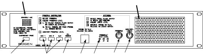
MCP35A Control Panel
Front Panel
1
9
RELEASE |
2 |
3 |
4 |
5 |
6 |
7 |
8 |
1.CONSOLE MIC - Used as microphone 1 or in conjunction with the emergency page or press-to-talk/release- to-listen (intercom) push-buttons. This mic is always used for two-way intercom calls, using the green button, and emergency paging using the red button. No external mic can replace the console mic for these functions.
2.EMERGENCY PAGE — Red push-button — Used to make announcements to all speaker stations. Announcements made using this button override all program distribution and/or switchbank settings.
3.PROGRAM DISTRIBUTION — Push-buttons — Used to make input source selections. Choose from or mix input from MIC 1 (console or external microphone), MIC 2 (external microphone), or AUX (tuner/cassette player), as desired.
4.ALL ROOMS — Push-button — Used to distribute a program to all speaker stations with selector panel switches set to either the “A” or “O” channel.
5.INTERCOM PRESS-TO-TALK/RELEASE TO LISTEN — Push-button — Used to communicate with the speaker station selected from switchbank channel “C”. This does not affect program distribution to other stations.
6.PROGRAM TALK LEVEL - LED indicators — N (normal) lights green to indicate proper signal level; P (peak) lights amber to indicate occasional higher than normal signal level; O (overload) lights red to indicate possible signal clip.
7.PROGRAM — Amber knob — Used to adjust volume level to speaker stations.
8.MONITOR/LISTEN — Green knob — Used to adjust the volume level to the front panel speaker.
9.FRONT PANEL SPEAKER — Used to monitor a program or to listen to a station via the intercom (C) channel.
6
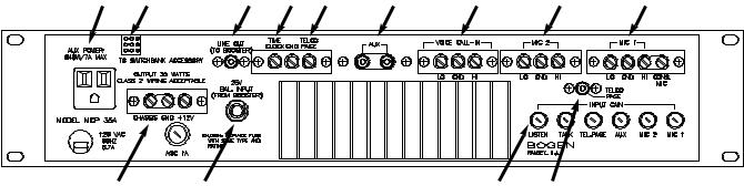
MCP35A Control Panel
Rear View
9 |
8 |
7 |
6 |
5 |
4 |
3 |
2 |
1 |
10 |
11 |
12 |
13 |
1.MIC 1 — Connections for an external mic (MIC 1). When the PROGRAM DISTRIBUTION button MIC 1 is pressed, the microphone connected here becomes active. As shipped from the factory, a link is installed between the HI and CONS MIC terminals. This makes the CONSOLE MIC act as MIC 1. When the link is removed, an external microphone can be connected to act as MIC 1 and the CONSOLE MIC will no longer be active when the MIC 1 button is pressed.
Note: The CONSOLE MIC is always used when the EMERGENCY PAGE button is pressed and when using the green INTERCOM PUSH-TO-TALK button (the user cannot change this). The external mic must be a low-impedance balanced mic (phantom power is also available for condenser mics).
2.MIC 2 — Connections for an external mic (MIC 2). When the PROGRAM DISTRIBUTION button MIC 2 is pressed, the microphone connected here becomes active. The external mic must be a low-impedance balanced mic (phantom power is also available for condenser mics).
3.VOICE CALL-IN — Allows retro fitting to older voice call-in systems with call-in switches connected in parallel. When a call-in switch is activated, an intercom channel is opened to the MCP35A control panel speaker so that the caller can announce verbally which room is calling. Systems that use this style of call-in will not see an annunciator light on the SBA225 room selector panel.
4.AUX — A high-impedance unbalanced input for auxiliary music sources. This input only becomes active when the PROGRAM DISTRIBUTION button AUX button is pressed.
5.TELCO PAGE — Shorting the TELCO PAGE terminal to GND activates a page from either MIC 2 or the TELCO INPUT (selected by an internal jumper).
6.TIME CLOCK — Shorting the TIME CLOCK terminal to GND produces a tone signal in all speakers.
7.LINE OUT — Provides an input signal that can be connected to the input of an external booster amp. Works in conjunction with the 25V BAL INPUT to allow replacement of the MCP-35A control panel’s built-in amplifier with a higher power amplifier.
8.SWITCHBANK CONNECTOR — SBA225 switchbank is connected to the MCP35A panel through this connector.
9.AUX POWER — An AC power outlet for auxiliary equipment.
10.12V Power Terminals — Chassis, ground, +12V DC supply, 750mA for powering up to 3 SCR25A modules.
11.25V BAL INPUT — The output of an external booster amp is connected at this 1/4” stereo phone jack. Works in conjunction with the LINE OUT connector see #7 above.
12.INPUT GAIN — Input level adjustments for all input sources.
13.TELCO PAGE — Alternate input for MIC 2 allows connection of Bogen model WMT1A for providing a 600ohm balanced telephone input.
7
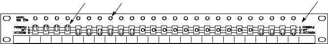
SBA225 Speaker Selector Panel
Front View
1 |
2 |
3 |
1.Room selector switch — Position of the room switch controls the type of audio program material delivered to the room speaker.
2.Call annunciators — Lights to indicate a room has placed an intercom request from a call switch
3.Program busses — A room speaker can be turned off or connected to one of two audio busses. The program A bus allows continuous audio to play into the room from an audio source selected on the MCP35A control panel. The Intercom C bus allows two-way intercom communication from any room whose selector switch is placed in this position.
8
 Loading...