


Radio / Cassette
Lima CR 47
Operating instructions

Table of Contents |
|
Features ......................................................................................................................................... |
19 |
Traffic Safety and Precautions ....................................................................................................... |
19 |
Detachable Face (Release Panel) ................................................................................................. |
20 |
Electrical Connections ................................................................................................................... |
21 |
Installation ...................................................................................................................................... |
23 |
Maintenance .................................................................................................................................. |
25 |
Location of Controls ....................................................................................................................... |
26 |
Instructions – General Operation ................................................................................................... |
27 |
Audio Operation ............................................................................................................................. |
28 |
Radio Operation ............................................................................................................................. |
29 |
Cassette Tape Player Operation .................................................................................................... |
30 |
Troubleshooting Guide .................................................................................................................. |
31 |
Blaupunkt Telephone Hotline ......................................................................................................... |
31 |
Specifications ................................................................................................................................. |
32 |
18

Features
•Radio Features
-15 FM/5 AM Presets, Including 5 FM and 5 AM Travelstore Presets
-Station Scan
-Local/Distant Seek and Manual Tuning
•Cassette Tape Player Features
-Auto-Reverse Cassette Mechanism
-True Fast-Forward/Rewind
-Hard Permalloy Tape Head
-Radio Monitor with Radio Preset Access
•Audio Features:
-10 Watts x 4 Channel Integrated Amplifier
-Adjustable Maximum Turn-On Volume
-Bass, Treble, Balance and Fader Control
-Loudness Button
-Mute Button
•Other Features:
-Detachable Face
-Illumination, Amber Night Design
-Display Priority Control
-Temporary Display Change Control
-Clock Recall
-179 x 50 x 150 mm DIN/ISO Chassis
-Detachable Wire Harness
-Snap-In DIN Sleeve and Mounting Hardware
Your unit’s detachable front faceplate makes the unit useless to would-be thieves.
Designed, Engineered and Manufactured By Blaupunkt.
Traffic Safety and Precautions
•Do not adjust your unit in difficult driving conditions that demand your full attention.
•As the driver of a motor vehicle, it is your responsibility to pay attention to the traffic situation at all times. Never use your unit in a way that could distract you.
•Always make sure that you are still able to hear any warning signals coming from outside of the vehicle, such as police or fire engine sirens, so that you can react accordingly.
•If your vehicle was parked in direct sunlight resulting in a considerable rise in temperature inside the vehicle, allow the unit to cool off before operating it.
DEUTSCH
ENGLISH
FRANÇAIS ITALIANO NEDERLANDS SVENSKA ESPAÑOL PORTUGUÊS
19
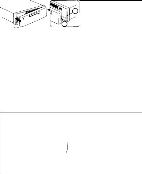
Detachable Face (Release Panel)
Detaching and Attaching the Face:
The face of this unit can be detached and taken with you to prevent it from being stolen.
Detaching the Face:
Press the REL (Release) Button and detach the face by gently pulling it off as illustrated.
Note: Do not pull it straight out from the chassis. Be sure not to drop the face when detaching it from the chassis. Do not expose the face to direct sunlight, heat sources such as hot air ducts or leave it in a humid place.
Attaching the Face:
Apply the right hand side of the face to the chassis by sliding (part B) of the face to (part A) at the front of the chassis. Gently push the left side of the face against the front of the chassis until it snaps into place.
Note: Make sure that the face is inserted right side up. Do not press against the display window. Do not press hard against the face when attaching it to the chassis, it may be easily attached with gentle pressure.
Affixing Faceplate For Retail Display:
The faceplate can be affixed to the unit’s chassis, which is desirable for a retail display, for example. This should only be done in situations where the unit can be accessed from behind the mounting surface. Once the faceplate is affixed, the release keys cannot be used to remove the chassis.
To affix the faceplate:
Insert the black bolt into the hole at the left front of the top of the radio. See * below.
*
A
B
20
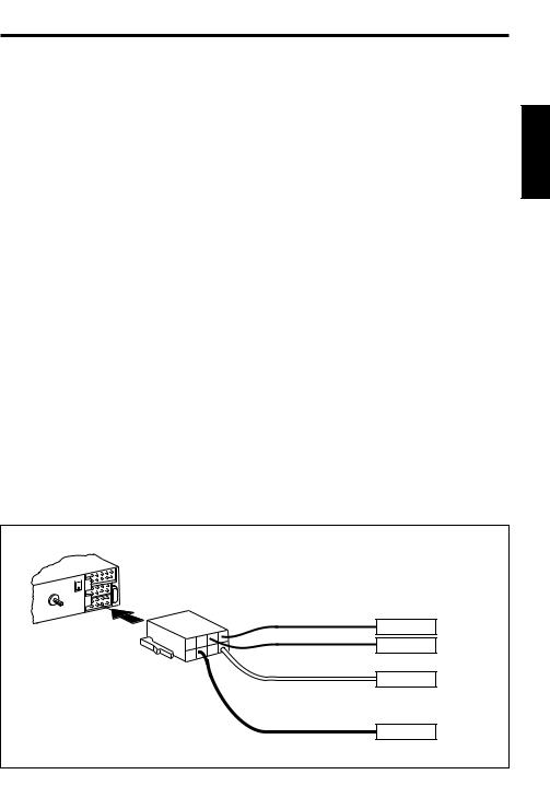
Electrical Connections
To avoid the aggravation of costly mistakes and serious damage, please carefully read all of the instructions before you begin. Carefully follow all instructions.
General Recommendations
•If you’re not confident that you can install the unit correctly, have it installed by a qualified
Blaupunkt installation technician.
•Use this unit only with negative ground 12 Volt (11-16 Volt) direct current (DC).
•Be sure to detach the faceplate before you start to connect or install the unit.
•We recommend making and testing all electrical connections before installing the unit. Connect the leads (wires) according to instructions and diagram below.
Electrical Connection Instructions
1.Disconnect the vehicle battery’s negative terminal before making connections.
2.Connect the speakers and/or external amplifiers (if you have any) following the guidelines in the “Speaker Connection” section below.
3.Connect the antenna output lead to the antenna motor trigger input terminal (if you have one). The total amperage required of the antenna lead must not exceed 100 mA. Do not connect the antenna lead to the antenna’s power supply input.
4.Connect the ground lead to a grounded metal part on the vehicle. We recommend grounding all audio system ground leads (head unit, external amplifier, etc.) to a common grounding point, preferably a non-painted surface under the instrument panel.
5.Connect the battery input lead to a source of constant battery power, preferably a terminal to an appropriate slot in the fuse box.
6.Connect the ignition input lead only after the other leads are connected. Be sure to connect the ignition lead to a positive (+) 12 Volt power terminal that is energized only when the ignition key is set to the on position or accessory position.
7.Cover the ends of any unused leads with electrical tape. This will prevent them from touching the vehicle or each other and causing a short-circuit and damage to the radio or vehicle.
8.Reconnect the vehicle’s battery.
9.Verify that no fuses have blown.
10.Plug the harness into the unit.
Electrical Connections
5A
Ignition
+12V
Antenna
Ground –
Battery +12V
DEUTSCH
ENGLISH
FRANÇAIS ITALIANO NEDERLANDS SVENSKA ESPAÑOL PORTUGUÊS
21
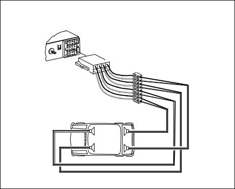
Speaker Connections
Speaker Connections
5A
RR |
RF |
LF |
LR |
|
|
+
-
+
-
+
-
+
-
RF |
RR |
LF |
LR |
Attach the faceplate and test the unit.
Once the connections have been successfully made, you can begin to mount the unit.
22
 Loading...