


In Car Video
IVSC-5502
Operating and installation instructions
http://www.blaupunkt.com

CONTENTS
General information ............... |
11 |
Installation and safety notices ........ |
11 |
Accessories .................................. |
11 |
Supplied parts ........................ |
12 |
Switching on/off .................... |
12 |
Switching on the signal controller .. 12 Switching off the signal controller .. 12
Settings .................................. |
13 |
External monitor switch (Fig. 2)...... |
13 |
Monitor connections ...................... |
13 |
IR remote control ................... |
13 |
Functions ...................................... |
13 |
Settings for Audio OUT ................. |
14 |
Installation.............................. |
15 |
Installation and safety notices ........ |
15 |
Positive connection ....................... |
15 |
Switching positive ......................... |
15 |
Fuse.............................................. |
15 |
Negative (ground) connection ........ |
15 |
Specifications ........................ |
16 |
Features ........................................ |
17 |
Connection diagrams ............. |
72 |
10

GENERAL INFORMATION
General information
Thank you for choosing a Blaupunkt product. We hope you enjoy using this new piece of equipment.
Please read these operating instructions before using the equipment for the first time.
The Blaupunkt editors are constantly working on making the operating instructions clearer and easier to understand. However, if you still have any questions on how to operate the device, please contact your dealer or the telephone hotline for your country. You will find the telephone number printed at the back of this booklet.
We provide a manufacturer guarantee for our products bought within the European Union. You can view the guarantee conditions at www.blaupunkt.de or ask for them directly at:
Blaupunkt GmbH
Hotline
Robert Bosch Str. 200
D-31139 Hildesheim
Installation and safety notices
Before connecting your signal controller, please read the following information carefully.
The battery’s negative terminal must be disconnected for the entire time it takes to install and connect this device.
When doing so, observe the vehicle manufacturer’s safety notices (airbags, alarm systems, trip computers, immobilizers).
Before drilling any holes, make sure that no installed cables or vehicle components can be damaged.
When installing the signal controller, select a location in the vehicle that allows you to attach it firmly into place using screws. The installation location should be such that the signal controller does not get in the way of the driver and cannot endanger the occupants in the event of the vehicle suddenly coming to a halt, for instance, during an emergency stop.
The IR remote control should not be installed within the inflation range of airbags (driver, passenger side, side airbags) or in any position where it could be struck by the vehicle occupants’ heads or knees.
With regard to the installation location and the attachment using an adhesive pad, check and ensure that the holding strength of the installation surface is sufficient and suitable for all situations and safety requirements.
Accessories
We recommend you use accessories that have been approved by Blaupunkt.
DEUTSCH ENGLISH FRANÇAIS ITALIANO NEDERLANDS SVENSKA ESPAÑOL PORTUGUÊS DANSK
11
SUPPLIED PARTS |
SWITCHING ON/OFF |
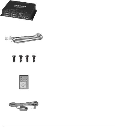
Supplied parts
The signal controller is supplied with all the parts listed below. Please check that the range of parts supplied with your device is complete. If one of the listed parts is missing, please contact your dealer immediately.
● Signal controller 7 607 003 551
●Connecting cable
●Screws
●IR remote control
●IR receiver
●Operating and installation instructions
Switching on/off
Switching on the signal controller
The signal controller is switched on via the “+12V ignition” switching line by the connected control device.
Switching off the signal controller
The signal controller is switched off via the “+12V ignition” switching line by the connected control device.Switching on/ off.
12
 Loading...