


LPB2810A
LPB2826A
LPB2848A
PoE+ Gigabit Managed Switch Eco
User Manual
An affordable managed switch with the power to be a key component of your network infrastructure.
Customer
Support
Information
Order toll-free in the U.S.: Call 877-877-BBOX (outside U.S. call 724-746-5500)
FREE technical support 24 hours a day, 7 days a week: Call 724-746-5500 or fax 724-746-0746 Mailing address: Black Box Corporation, 1000 Park Drive, Lawrence, PA 15055-1018
Web site: www.blackbox.com • E-mail: info@blackbox.com

Trademarks
Trademarks Used in this Manual
Black Box and the Double Diamond logo are registered trademarks of BB Technologies, Inc.
Any other trademarks mentioned in this manual are acknowledged to be the property of the trademark owners.
We‘re here to help! If you have any questions about your application or our products, contact Black Box Tech Support at 724-746-5500 or go to blackbox.com and click on “Talk to Black Box.”
You’ll be live with one of our technical experts in less than 30 seconds.
Page 2 |
724-746-5500 | blackbox.com |
LPB2810A |
|
|

FCC Statement
Federal Communications Commission and Industry Canada Radio Frequency Interference
Statements
This equipment generates, uses, and can radiate radio-frequency energy, and if not installed and used properly, that is, in strict accordance with the manufacturer’s instructions, may cause interference to radio communication. It has been tested and found to comply with the limits for a Class A computing device in accordance with the specifications in Subpart B of Part 15 of FCC rules, which are designed to provide reasonable protection against such interference when the equipment is operated in a commercial environment. Operation of this equipment in a residential area is likely to cause interference, in which case the user at his own expense will be required to take whatever measures may be necessary to correct the interference.
Changes or modifications not expressly approved by the party responsible for compliance could void the user’s authority to operate the equipment.
This digital apparatus does not exceed the Class A limits for radio noise emission from digital apparatus set out in the Radio
Interference Regulation of Industry Canada.
Le présent appareil numérique n’émet pas de bruits radioélectriques dépassant les limites applicables aux appareils numériques de la classe A prescrites dans le Règlement sur le brouillage radioélectrique publié par Industrie Canada.
LPB2810A |
724-746-5500 | blackbox.com |
Page 3 |
|
|

NOM Statement
Instrucciones de Seguridad
(Normas Oficiales Mexicanas Electrical Safety Statement)
1.Todas las instrucciones de seguridad y operación deberán ser leídas antes de que el aparato eléctrico sea operado.
2.Las instrucciones de seguridad y operación deberán ser guardadas para referencia futura.
3.Todas las advertencias en el aparato eléctrico y en sus instrucciones de operación deben ser respetadas.
4.Todas las instrucciones de operación y uso deben ser seguidas.
5.El aparato eléctrico no deberá ser usado cerca del agua—por ejemplo, cerca de la tina de baño, lavabo, sótano mojado o cerca de una alberca, etc.
6.El aparato eléctrico debe ser usado únicamente con carritos o pedestales que sean recomendados por el fabricante.
7.El aparato eléctrico debe ser montado a la pared o al techo sólo como sea recomendado por el fabricante.
8.Servicio—El usuario no debe intentar dar servicio al equipo eléctrico más allá a lo descrito en las instrucciones de operación. Todo otro servicio deberá ser referido a personal de servicio calificado.
9.El aparato eléctrico debe ser situado de tal manera que su posición no interfiera su uso. La colocación del aparato eléctrico sobre una cama, sofá, alfombra o superficie similar puede bloquea la ventilación, no se debe colocar en libreros o gabinetes que impidan el flujo de aire por los orificios de ventilación.
10.El equipo eléctrico deber ser situado fuera del alcance de fuentes de calor como radiadores, registros de calor, estufas u otros aparatos (incluyendo amplificadores) que producen calor.
11.El aparato eléctrico deberá ser connectado a una fuente de poder sólo del tipo descrito en el instructivo de operación, o como se indique en el aparato.
12.Precaución debe ser tomada de tal manera que la tierra fisica y la polarización del equipo no sea eliminada.
13.Los cables de la fuente de poder deben ser guiados de tal manera que no sean pisados ni pellizcados por objetos colocados sobre o contra ellos, poniendo particular atención a los contactos y receptáculos donde salen del aparato.
14.El equipo eléctrico debe ser limpiado únicamente de acuerdo a las recomendaciones del fabricante.
15.En caso de existir, una antena externa deberá ser localizada lejos de las lineas de energia.
16.El cable de corriente deberá ser desconectado del cuando el equipo no sea usado por un largo periodo de tiempo.
17.Cuidado debe ser tomado de tal manera que objectos liquidos no sean derramados sobre la cubierta u orificios de ventilación.
18.Servicio por personal calificado deberá ser provisto cuando:
A:El cable de poder o el contacto ha sido dañado; u
B:Objectos han caído o líquido ha sido derramado dentro del aparato; o
C:El aparato ha sido expuesto a la lluvia; o
D:El aparato parece no operar normalmente o muestra un cambio en su desempeño; o
E:El aparato ha sido tirado o su cubierta ha sido dañada.
Page 4 |
724-746-5500 | blackbox.com |
LPB2810A |
|
|

Table of Contents
Table of Contents |
|
1. Overview ............................................................................................................................................................................... |
9 |
1.1 Initial Configuration........................................................................................................................................................ |
10 |
1.2 Connecting to PCs, Servers, Hubs, and Switches........................................................................................................... |
13 |
1.3 Network Wiring Connections......................................................................................................................................... |
14 |
2. System Configuration............................................................................................................................................................ |
15 |
2.1 System Information........................................................................................................................................................ |
15 |
2.1.1 Information.......................................................................................................................................................... |
15 |
2.1.2 Configuration...................................................................................................................................................... |
17 |
2.1.3 CPU Load............................................................................................................................................................ |
18 |
2.2 Time ............................................................................................................................................................................. |
19 |
2.2.1 Manual................................................................................................................................................................ |
19 |
2.2.2 NTP..................................................................................................................................................................... |
21 |
2.3 Account......................................................................................................................................................................... |
21 |
2.3.1 Users................................................................................................................................................................... |
22 |
2.3.2 Privilege Levels.................................................................................................................................................... |
23 |
2.4 IP (Internet Protocol)...................................................................................................................................................... |
25 |
2.4.1 IPv4..................................................................................................................................................................... |
25 |
2.4.2 IPV6.................................................................................................................................................................... |
27 |
2.5 Syslog............................................................................................................................................................................. |
28 |
2.5.1 Configuration...................................................................................................................................................... |
28 |
2.5.2 Log...................................................................................................................................................................... |
29 |
2.5.3 Detailed Log........................................................................................................................................................ |
30 |
2.6 SNMP............................................................................................................................................................................. |
31 |
2.6.1 System................................................................................................................................................................. |
31 |
2.6.2 Communities....................................................................................................................................................... |
32 |
2.6.3 Users................................................................................................................................................................... |
33 |
2.6.4 Groups................................................................................................................................................................ |
35 |
2.6.5 Views.................................................................................................................................................................. |
36 |
2.6.6 Access................................................................................................................................................................. |
37 |
2.6.7 Trap..................................................................................................................................................................... |
38 |
3. Configuration........................................................................................................................................................................ |
40 |
3.1 Port ............................................................................................................................................................................. |
40 |
3.1.1 Configuration....................................................................................................................................................... |
40 |
3.1.2 Port Description................................................................................................................................................... |
42 |
3.1.3 Traffic Overview.................................................................................................................................................. |
43 |
3.1.4 Detailed Statistics................................................................................................................................................ |
44 |
3.1.5 Qos Statistics....................................................................................................................................................... |
46 |
3.1.6 SFP Information................................................................................................................................................... |
47 |
3.1.7 EEE...................................................................................................................................................................... |
48 |
3.2 ACL ............................................................................................................................................................................. |
50 |
3.2.1 Ports.................................................................................................................................................................... |
50 |
3.2.2 Rate Limiters....................................................................................................................................................... |
52 |
3.2.3 Access Control List.............................................................................................................................................. |
53 |
3.2.4 ACL Status.......................................................................................................................................................... |
55 |
3.3 Aggregation................................................................................................................................................................... |
57 |
3.3.1 Static Trunk......................................................................................................................................................... |
57 |
3.3.2 LACP................................................................................................................................................................... |
59 |
LPB2810A |
724-746-5500 | blackbox.com |
Page 5 |
|
|

Table of Contents
3.4 Spanning Tree................................................................................................................................................................ |
63 |
|
|
3.4.1 Bridge Settings.................................................................................................................................................... |
64 |
|
3.4.2. MSTI Mapping................................................................................................................................................... |
65 |
|
3.4.3 MSTI Priorities..................................................................................................................................................... |
66 |
|
3.4.4 CIST Ports........................................................................................................................................................... |
67 |
|
3.4.5 MSTI Ports.......................................................................................................................................................... |
69 |
|
3.4.6 Bridge Status....................................................................................................................................................... |
70 |
|
3.4.7 Port Status.......................................................................................................................................................... |
71 |
|
3.4.8 Port Statistics...................................................................................................................................................... |
72 |
3.5 |
Loop Detection............................................................................................................................................................ |
73 |
3.6 IGMP Snooping............................................................................................................................................................. |
74 |
|
|
3.6.1 Basic Configuration............................................................................................................................................. |
74 |
|
3.6.2 VLAN Configuration........................................................................................................................................... |
75 |
|
3.6.3 Port Group Filtering............................................................................................................................................ |
76 |
|
3.6.4 Status.................................................................................................................................................................. |
78 |
|
3.6.5 Group Information.............................................................................................................................................. |
79 |
|
3.6.6 IPv4 SSM information......................................................................................................................................... |
80 |
3.7 MLD Snooping............................................................................................................................................................... |
82 |
|
|
3.7.1 Basic Configuration.............................................................................................................................................. |
82 |
|
3.7.2 VLAN Configuration............................................................................................................................................ |
84 |
|
3.7.3 Port Group Filtering............................................................................................................................................. |
85 |
|
3.7.4 Status.................................................................................................................................................................. |
86 |
|
3.7.5 Group Information.............................................................................................................................................. |
87 |
|
3.7.6 IPv6 SSM Information.......................................................................................................................................... |
88 |
3.8 MVR ............................................................................................................................................................................. |
89 |
|
|
3.8.1 Configuration...................................................................................................................................................... |
89 |
|
3.8.2 Groups Information............................................................................................................................................ |
90 |
|
3.8.3 Statistics.............................................................................................................................................................. |
91 |
3.9 LLDP ............................................................................................................................................................................. |
92 |
|
|
3.9.1 LLDP Configuration............................................................................................................................................. |
92 |
|
3.9.2 LLDP Neighbors.................................................................................................................................................. |
94 |
|
3.9.3 LLDP-MED Configuration.................................................................................................................................... |
95 |
|
3.9.4 LLDP-MED Neighbors........................................................................................................................................ |
100 |
|
3.9.5 PoE.................................................................................................................................................................... |
103 |
|
3.9.6 EEE.................................................................................................................................................................... |
104 |
|
3.9.7 Port Statistics..................................................................................................................................................... |
105 |
3.10 PoE ........................................................................................................................................................................... |
107 |
|
|
3.10.1 Configuration.................................................................................................................................................. |
107 |
|
3.10.2 Status.............................................................................................................................................................. |
108 |
3.11 |
Filtering Data Base..................................................................................................................................................... |
109 |
|
3.11.1 Configuration................................................................................................................................................... |
109 |
|
3.11.2 Dynamic MAC Table........................................................................................................................................ |
112 |
3.12 VLAN.......................................................................................................................................................................... |
113 |
|
|
3.12.1 VLAN Membership.......................................................................................................................................... |
114 |
|
3.12.2 Ports................................................................................................................................................................ |
115 |
|
3.12.3 Switch Status................................................................................................................................................... |
117 |
|
3.12.4 Port Status....................................................................................................................................................... |
118 |
|
3.12.5 Private VLANs.................................................................................................................................................. |
119 |
|
3.12.6 MAC-Based VLAN........................................................................................................................................... |
121 |
|
3.12.7 Protocol-Based VLAN...................................................................................................................................... |
124 |
3.13 Voice VLAN................................................................................................................................................................ |
127 |
|
Page 6 |
724-746-5500 | blackbox.com |
LPB2810A |
|
|

Table of Contents
3.13.1 Configuration................................................................................................................................................... |
127 |
3.13.2 OUI.................................................................................................................................................................. |
129 |
3.14 GARP.......................................................................................................................................................................... |
130 |
3.14.1 Configuration.................................................................................................................................................. |
130 |
3.14.2 Statistics.......................................................................................................................................................... |
132 |
3.15 GVRP.......................................................................................................................................................................... |
133 |
3.15.1 Configuration................................................................................................................................................... |
133 |
3.15.2 Statistics.......................................................................................................................................................... |
135 |
3.16 QoS ........................................................................................................................................................................... |
136 |
3.16.1 Port Classification............................................................................................................................................ |
136 |
3.16.2 Port Policing.................................................................................................................................................... |
137 |
3.16.3 Port Scheduler................................................................................................................................................. |
139 |
3.16.4 Port Shaping.................................................................................................................................................... |
141 |
3.16.5 Port Tag Remarking......................................................................................................................................... |
143 |
3.16.6 Port DSCP........................................................................................................................................................ |
144 |
3.16.7 DSCP-Based QoS............................................................................................................................................. |
145 |
3.16.8 DSCP Translation............................................................................................................................................. |
147 |
3.16.9 DSCP Classification.......................................................................................................................................... |
149 |
3.16.10 QoS Control List Configuration...................................................................................................................... |
150 |
3.16.11 QCL Status..................................................................................................................................................... |
153 |
3.16.12 Storm Control................................................................................................................................................ |
154 |
3.17 Thermal Protection..................................................................................................................................................... |
155 |
3.17.1 Configuration................................................................................................................................................... |
155 |
3.17.2 Status............................................................................................................................................................... |
156 |
3.18 sFlow Agent............................................................................................................................................................... |
157 |
3.18.1 sFlow Collector................................................................................................................................................ |
157 |
3.18.2 Sampler........................................................................................................................................................... |
158 |
3.19 Loop Protection.......................................................................................................................................................... |
160 |
3.19.1 Configuration................................................................................................................................................... |
160 |
3.19.2 Status.............................................................................................................................................................. |
161 |
3.20 Single IP..................................................................................................................................................................... |
162 |
3.21 Easy Port.................................................................................................................................................................... |
164 |
3.22 Mirroring.................................................................................................................................................................... |
166 |
3.23 Trap Event Severity..................................................................................................................................................... |
167 |
3.24 SMTP Configuration................................................................................................................................................... |
168 |
3.25 UPnP.......................................................................................................................................................................... |
169 |
4. Security ........................................................................................................................................................................... |
170 |
4.1. IP Source Guard........................................................................................................................................................... |
170 |
4.1.1 Configuration.................................................................................................................................................... |
170 |
4.1.2 Static Table........................................................................................................................................................ |
171 |
4.1.3 Dynamic Table................................................................................................................................................... |
172 |
4.2 ARP Inspection............................................................................................................................................................. |
173 |
4.2.1 Configuration.................................................................................................................................................... |
173 |
4.2.2 Static Table........................................................................................................................................................ |
174 |
4.2.3 Dynamic Table.................................................................................................................................................. |
175 |
4.3 DHCP Snooping........................................................................................................................................................... |
176 |
4.3.1 Configuration.................................................................................................................................................... |
176 |
4.3.2 Statistics............................................................................................................................................................ |
177 |
4.4 DHCP Relay.................................................................................................................................................................. |
178 |
4.4.1 Configuration.................................................................................................................................................... |
178 |
LPB2810A |
724-746-5500 | blackbox.com |
Page 7 |
|
|

Table of Contents
4.4.2 Statistics............................................................................................................................................................ |
179 |
4.5 NAS ........................................................................................................................................................................... |
181 |
4.5.1 Configuration.................................................................................................................................................... |
181 |
4.5.2 Switch Status.................................................................................................................................................... |
187 |
4.5.3 Port Status........................................................................................................................................................ |
188 |
4.6 AAA ........................................................................................................................................................................... |
190 |
4.6.1 Configuration.................................................................................................................................................... |
190 |
4.6.2 RADIUS Overview............................................................................................................................................. |
193 |
4.6.3 RADIUS Details................................................................................................................................................. |
194 |
4.7 Port Security................................................................................................................................................................. |
195 |
4.7.1 Limit Control...................................................................................................................................................... |
195 |
4.7.2 Switch Status..................................................................................................................................................... |
197 |
4.7.3 Port Status......................................................................................................................................................... |
199 |
4.8 Access Management.................................................................................................................................................... |
200 |
4.8.1 Configuration.................................................................................................................................................... |
200 |
4.8.2 Statistics............................................................................................................................................................ |
201 |
4.9 SSH ........................................................................................................................................................................... |
202 |
4.10 HTTPS........................................................................................................................................................................ |
203 |
4.11 Authentication Method.............................................................................................................................................. |
204 |
5. Maintenance........................................................................................................................................................................ |
205 |
5.1 Restart Device.............................................................................................................................................................. |
205 |
5.2 Firmware...................................................................................................................................................................... |
206 |
5.2.1 Firmware Upgrade............................................................................................................................................. |
206 |
5.2.2 Firmware Selection........................................................................................................................................... |
207 |
5.3 Save / Restore.............................................................................................................................................................. |
208 |
5.3.1 Factory Defaults................................................................................................................................................ |
208 |
5.3.2 Save Start.......................................................................................................................................................... |
209 |
5.3.3 Save User.......................................................................................................................................................... |
209 |
5.3.4 Restore User...................................................................................................................................................... |
211 |
5.4 Export / Import............................................................................................................................................................ |
212 |
5.4.1 Export Config.................................................................................................................................................... |
212 |
5.4.2 Import Config................................................................................................................................................... |
213 |
5.5 Diagnostics.................................................................................................................................................................. |
214 |
5.5.1 Ping................................................................................................................................................................... |
214 |
5.5.2 Ping6................................................................................................................................................................ |
215 |
5.5.3 VeriPHY............................................................................................................................................................. |
216 |
Appendix: Glossary of Web-Based Management Terms ......................................................................................................... |
217 |
Page 8 |
724-746-5500 | blackbox.com |
LPB2810A |
|
|

Chapter 1: Overview
1. Overview
This user’s manual provides step-by-step instructions for configuring and monitoring your PoE+ Gigabit Managed Switch Eco through the Web via an RJ-45 (serial) interface and Ethernet port. Detailed explanations of hardware and software functions are shown, along with examples of the operation for Web-based interface.
The PoE+ Gigabit Managed Switch Eco, part of the next generation of Web-managed switches from Black Box, provides a reliable infrastructure for your business network. This switch delivers the intelligent features you need to improve the availability of your critical business applications, to protect your sensitive information, and to optimize your network bandwidth to deliver information and applications more effectively. It provides the ideal combination of affordability and capabilities for entry-level networking. Whether you have a small business or enterprise application, this switch will enable you to create a more efficient, betterconnected workforce.
The PoE+ Gigabit Managed Switch Eco provides 10, 26, or 48 ports in a single device. Its features include:
•L2+ features provide better manageability, security, QoS, and performance.
•High port count design with all Gigabit Ethernet ports.
•Supports guest VLAN, voice VLAN, port-based, tag-based and protocol-based VLANs.
•Supports 802.3az Energy Efficient Ethernet standards.
•Supports 8K MAC table.
•Supports IPv6/ IPv4 Dual stack.
•Supports s-Flow.
•Supports Easy-Configuration-Port for easy implementation in IP phone, IP camera, or wireless environments.
LPB2810A |
724-746-5500 | blackbox.com |
Page 9 |
|
|
Chapter 1: Overview
1.1 Initial Configuration
This section details how to configure and manage the PoE+ Gigabit Managed Switch Eco through the Web user interface. This feature enables administrators to easily access and monitor the entire status of the switch through any one port of the switch. Statuses which may be monitored include status of the MIBs, activity of each port, status of spanning trees, port aggregation status, multicast traffic, VLAN and priority status, even illegal access records.
The default values of the PoE+ Gigabit Managed Switch Eco are listed in the table below:
|
Table 1-1: Using Web-based management. |
IP Address |
192.168.1.1 |
|
|
Subnet Mask |
255.255.255.0 |
|
|
Default |
192.168.1.254 |
|
|
Username |
admin |
|
|
Password |
|
|
|
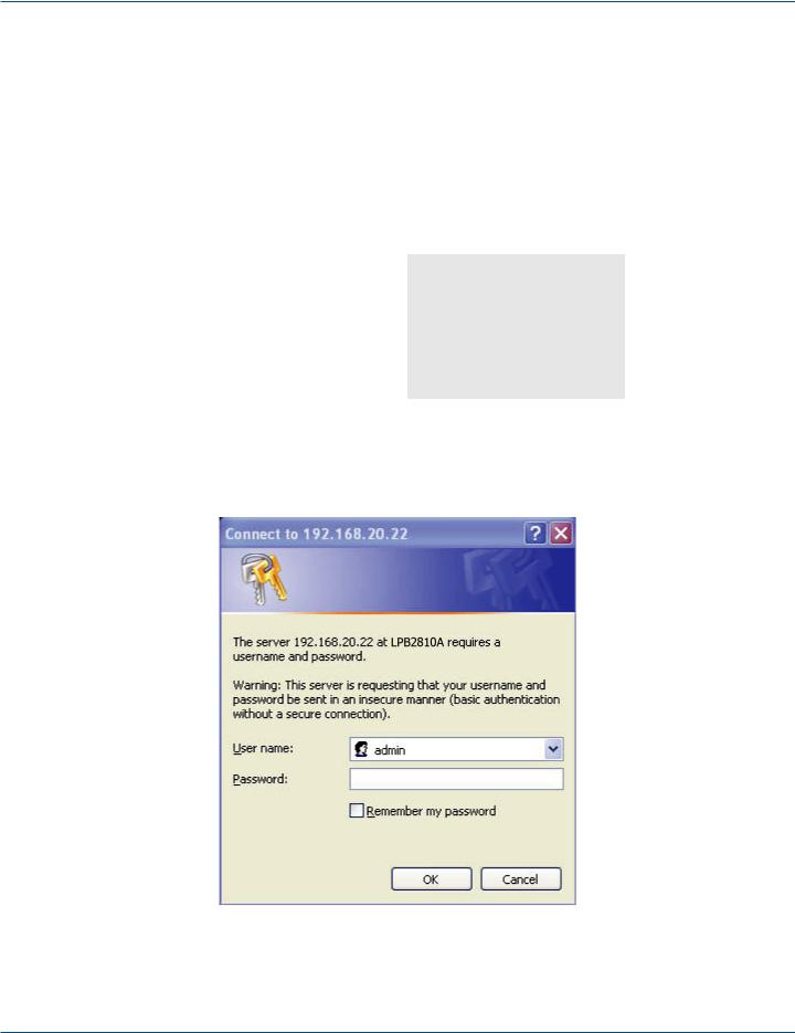
After the PoE+ Gigabit Managed Switch Eco has been configured in the interface, you can browse it. For instance, type http://192.168.1.1 in the address row in a browser. You will see the screen in Figure 1-1, requesting your username and password to log in and authenticate your access.
Figure 1-1. The login screen.
The default username is “admin” and password is empty. For the first use, please enter the default username and password, then click the <Login> button.
Page 10 |
724-746-5500 | blackbox.com |
LPB2810A |
|
|
Chapter 1: Overview
The login process now is completed. In this login menu, you must input the complete username and password respectively: the PoE+ Gigabit Managed Switch Eco will not give you a shortcut to username automatically. This may be inconvenient, but it is safer.
The PoE+ Gigabit Managed Switch Eco supports a simple user management function allowing only one administrator to configure the system at the same time. If there are two or more users using an administrator’s identity, it will only allow the one who logs in first to configure the system. The rest of the users, even with an administrator’s identity, can only monitor the system. Those who have no administrator’s identity can only monitor the system. There is a maximum of three users able to login simultaneously in the PoE+ Gigabit Managed Switch Eco.
NOTE: When you log in to the Switch Web Manager, you must first type the Username of the admin. The password must remain blank at this point, so simply press Enter. When you log in the PoE+ Gigabit Managed Switch Eco Web UI management, you can use either an ipv4 or ipv6 log in. To optimize the display, we recommend you use Microsoft® Internet Explorer® 6.0 or higher, Netscape® V7.1 or higher, or FireFox® V1.00 above and set the resolution 1024x768. The switch supports a neutral Web browser interface.
NOTE: the PoE+ Gigabit Managed Switch Eco enables the DHCP function, so if you do not have DHCP server to provide IP addresses to the switch, the switch default IP is 192.168.1.1.
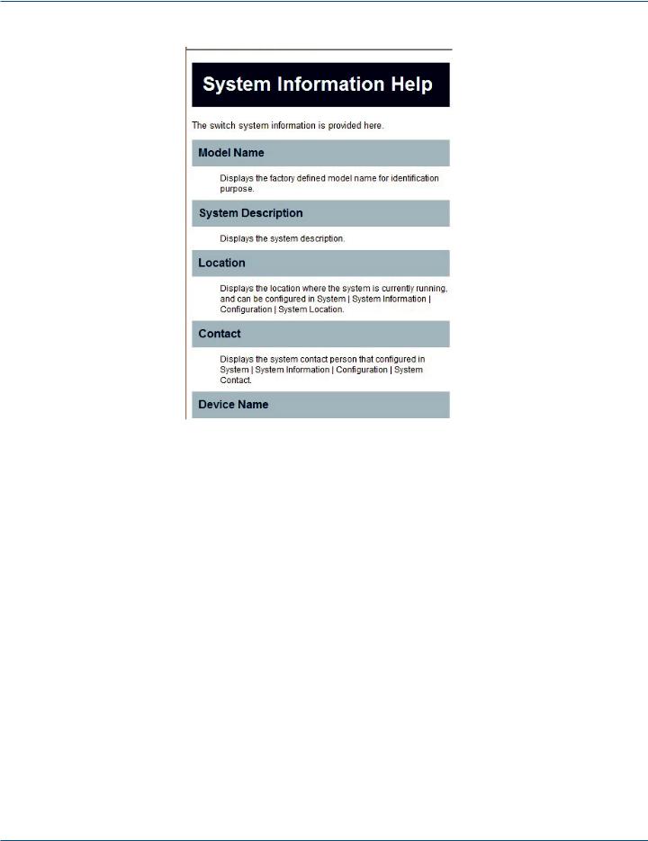
NOTE: If you need to configure the function or parameter, refer to those sections in the User Guide. Or, access the switch and click the “help“ under the Web GUI, and the switch will open its easy-to-use help content to teach you how to set the parameters, as shown in Figure 1-2.
Figure 1-2. Accessing the on-line help function.
LPB2810A |
724-746-5500 | blackbox.com |
Page 11 |
|
|
Chapter 1: Overview
Figure 1-2 (Continued). Accessing the on-line help function.
Connecting Network Devices
The switch is designed to be connected to 10-, 100-, or 1000-Mbps network cards in PCs and servers, as well as to other switches and hubs. It may also be connected to remote devices using optional SFP transceivers.
Twisted-Pair Devices
Each device requires an unshielded twisted-pair (UTP) cable with RJ-45 connectors at both ends. Use Category 5, 5e, or 6 cable for 1000BASE-T connections, Category 5 or better for 100BASE-TX connections.
Cabling Guidelines
The RJ-45 ports on the switch support automatic MDI/MDI-X pinout configuration, so you can use standard straight-through twisted-pair cables to connect to any other network device (PCs, servers, switches, routers, or hubs).
See Section 4.2 of the LPB2810A Quick Start Guide, “Ethernet Cabling,“ for more information on cabling.
CAUTION: Do not plug a phone jack connector into an RJ-45 port. This will damage the switch. Use only twisted-pair cables with RJ-45 connectors that conform to FCC standards.
Page 12 |
724-746-5500 | blackbox.com |
LPB2810A |
|
|

Chapter 1: Overview
1.2 Connecting to PCs, Servers, Hubs, and Switches
Step 1: Attach one end of a twisted-pair cable segment to the device's RJ-45 connector.
Step 2. If the device is a network card and the switch is in the wiring closet, attach the other end of the cable segment to a modular wall outlet that is connected to the wiring closet. (See Section 1.3, “Network Wiring Connections.”) Otherwise, attach the other end to an available port on the switch. Make sure each twisted-pair cable does not exceed 328 feet (100 m) in length.
NOTE: Avoid using flow control on a port connected to a hub unless it is actually required to solve a problem. Otherwise backpressure jamming signals may degrade overall performance for the segment attached to the hub.
Step 3. As each connection is made, the Link LED (on the switch) corresponding to each port will light green (1000 Mbps) or amber (100 Mbps) to indicate that the connection is valid.
LPB2810A |
724-746-5500 | blackbox.com |
Page 13 |
|
|
Chapter 1: Overview
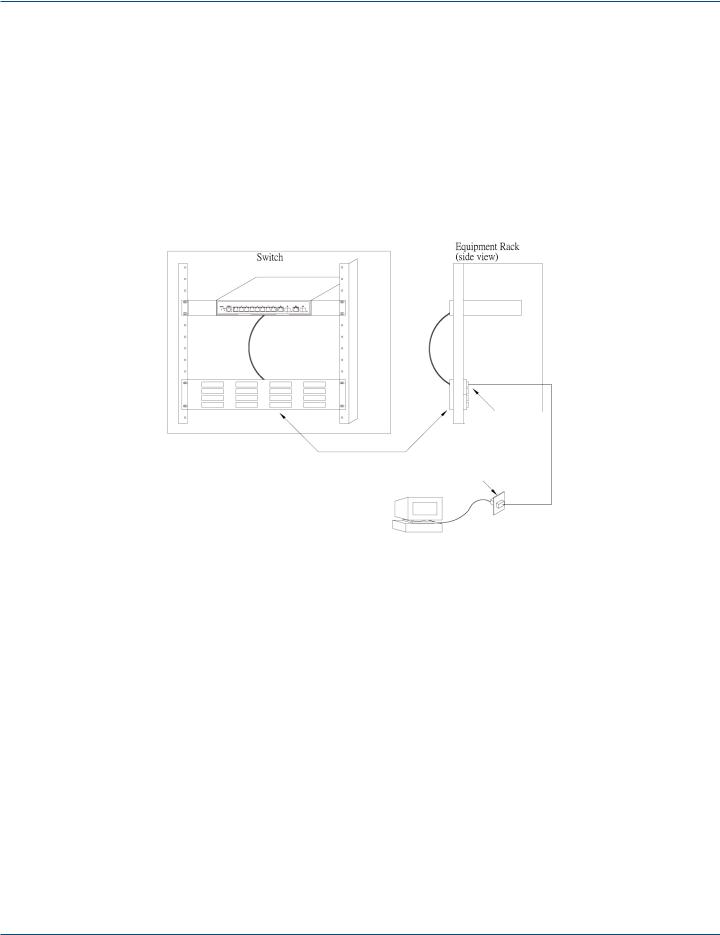
1.3 Network Wiring Connections
Today, the punchdown block is an integral part of many of the newer equipment racks. It is actually part of the patch panel. Instructions for making connections in the wiring closet with this type of equipment follows:
Step 1: Attach one end of a patch cable to an available port on the switch, and the other end to the patch panel.
Step 2. If not already in place, attach one end of a cable segment to the back of the patch panel where the punchdown block is located, and the other end to a modular wall outlet.
Step 3. Label the cables to simplify future troubleshooting. See Chapter 6 of the PoE+ Gigabit Managed Switch Eco Quick Start Guide: “Labeling Connections.“
|
|
|
|
Equipment Rack |
|
Switch |
|
(side view) |
Punchdown Block
Patch Panel
Wall
Figure 1-3. Network wiring connections.
Page 14 |
724-746-5500 | blackbox.com |
LPB2810A |
|
|
Chapter 2: System Configuration
2. System Configuration
This chapter describes all of the basic configration tasks, including the system information and any management of the switch (e.g., Time, Account, IP, Syslog, and SNMP).
2.1 System Information
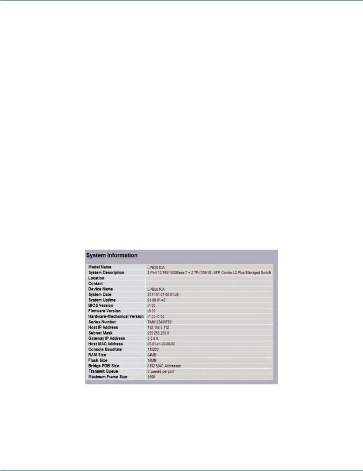
After logging in, the switch shows you the system information. This page is the default and tells you the basic information of the system, including “Model Name”, “System Description”, “Contact”, “Device Name”, “System Uptime”, “BIOS Version”, “Firmware Version”, “Hardware-Mechanical Version”, “Serial Number”, “Host IP Address”, “Host Mac Address”, “Device Port”, “RAM Size” , “Flash Size” etc. With this information, you will know the software version used, MAC address, serial number, how many ports good and so on, information you will need for troubleshooting or when contacting Tech Support.
2.1.1 Information
The switch system information is provided here.
Web interface
To configure System Information in the Web interface:
1.Click SYSTEM, System, and Information.
2.Specify the contact information for the system administrator as well as the name and location of the switch. Also indicate the local time zone by configuring the appropriate offset.
3.Click Refresh.
Figure 2-1. System Information screen.
Parameter Description
•Model Name: The model name of this device.
•System Description: This tells what this device is. Here, it is “8 port 10/100/1000 Base-T + 2-Port Dual Personality (RJ-45/SFP) Web Managed Switch”.
•Location: This is the location where this switch is put. User-defined.
LPB2810A |
724-746-5500 | blackbox.com |
Page 15 |
|
|

Chapter 2: System Configuration
•Contact: Enter the contact person’s name and phone here. You can configure this parameter through the device’s user interface or SNMP.
•Device Name: The name of the switch. User-defined.
•System Date: Show the system time of the switch. Its format: day of week, month, day, hours : minutes : seconds, year.
•System Uptime: The time accumulated since this switch is powered up. Its format is day, hour, minute, second.
•BIOS Version: The version of the BIOS in this switch.
•Firmware Version: The firmware version in this switch.
•Hardware-Mechanical Version: The figure before the hyphen is the version of electronic hardware; the one after the hyphen is the mechanical version.
•Serial Number: The serial number is assigned by the manufacturer.
•Host IP Address: The IP address of the switch.
•Host MAC Address: It is the Ethernet MAC address of the management agent in this switch.
•Device Port: Show all types and numbers of the port in the switch.
•RAM Size: The size of the RAM in this switch.
•Flash Size: The size of the flash memory in this switch.
•Bridge FDB Size: Displays the bridge FDB size information.
•Transmit Queue : Displays the device’s transmit hardware priority queue information.
•Maximum Frame Size: Displays the device’s maximum frame size information.
Page 16 |
724-746-5500 | blackbox.com |
LPB2810A |
|
|
Chapter 2: System Configuration
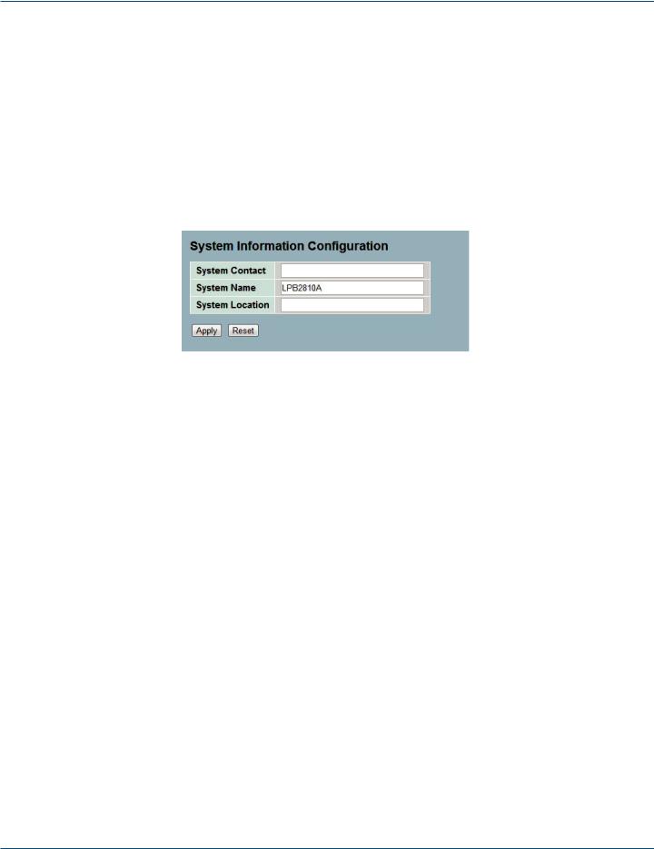
2.1.2 Configuration
You can identify the system by configuring the contact information, name, and location of the switch.
Web Interface
To configure System Information in the Web interface:
1.Click System, System Information, Configuration.
2.Write System Contact, System Name, System Location information in this page.
3.Click Save.
Figure 2-2. System Information Configuration screen.
Parameter Description
•System Contact: The textual identification of the contact person for this managed node, together with information on how to contact this person. The string length should be 0 to 255 characters, and the type of content permitted is the ASCII characters from 32 to 126.
•System Name: An administratively assigned name for this managed node. By convention, this is the node’s fully qualified domain name. A domain name is a text string drawn from letters (A-Z, a-z), numbers (0-9), and the minus sign (-). No space characters are permitted as part of a name. The first character must be an alpha character. And the first or last character must not be a minus sign. The string length should be 0 to 255.
•System Location: Describes the physical location of this node (e.g., telephone closet, 3rd floor). The string length should be 0 to 255 characters, and the content should be ASCII characters from 32 to 126.
LPB2810A |
724-746-5500 | blackbox.com |
Page 17 |
|
|
Chapter 2: System Configuration
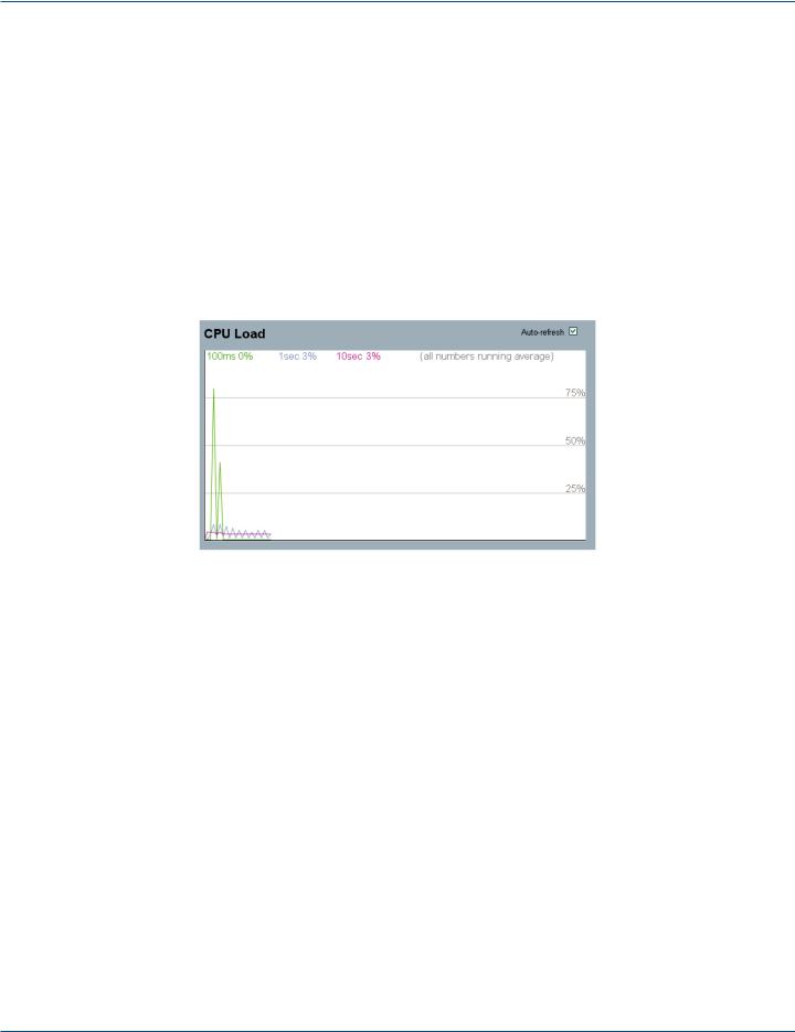
2.1.3 CPU Load
This page displays the CPU load, using an SVG graph. The load is measured as averaged over the last 100-ms, 1-second, and 10-second intervals. The last 120 samples are graphed, and the last numbers are displayed as text as well. To display the SVG graph, your browser must support the SVG format. Consult the SVG Wiki for more information on browser support. Specifically, at the time of writing, Microsoft Internet Explorer will need to have a plug-in installed to support SVG.
Web Interface
To configure System Information in the Web interface:
1.Click System, System Information, CPU Load.
2.Display the CPU Load on the screen.
3.Click Auto-refresh.
Figure 2-3: CPU Load screen.
Parameter Description
• To set the switch to auto-refresh the log, check “Auto-refresh.”
NOTE: The screen under “from” and “to” will display what you set on the “From” and “To” field information.
Page 18 |
724-746-5500 | blackbox.com |
LPB2810A |
|
|
Chapter 2: System Configuration
2.2 Time
This section describes how to configure the switch time, including Time Configuration and NTP Configuration.
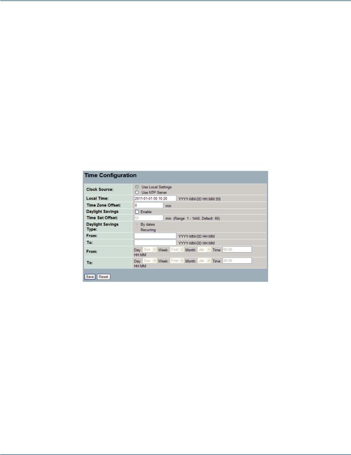
2.2.1 Manual
The switch provides manual and automatic ways to set the system time via NTP. Manual setting is simple. Input “Year”, “Month”, “Day”, “Hour”, “Minute” and “Second” within the valid value range indicated in each item.
Web Interface
To configure Time in the Web interface:
1.Click Time, Manual.
2.Specify the Time parameter in manual parameters.
3.Click Save.
Figure 2-4: The time configuration screen.
Parameter Description
•Clock Source: Select which clock source to use for the PoE+ Gigabit Managed Switch Eco. You can select “Use local Settings” or “Use NTP Server.”
•Local Time: Show the current time of the system.
•Time Zone Offset: Provides the time zone offset relative to UTC/GMT. The offset is given in minutes east of GMT. The valid range is from -720 to 720 minutes.
LPB2810A |
724-746-5500 | blackbox.com |
Page 19 |
|
|

Chapter 2: System Configuration
•Daylight Savings: Daylight savings time is used in some countries. If you select this setting, the unit will adjust the time, forward or backward in increments of one hour, between the starting date and the ending date that you select. For example, if you set the daylight savings offset to be 1 hour, when the time reaches the starting time, the system time will be increased one hour. And when the time reaches the ending time, the system time will be decreased one hour.
The switch supports valid configurable daylight savings times of –5 to +5 hours in one-hour increments. The zero for this parameter means you will not have to adjust the current time to enact daylight saving. However, remember that if you do set the unit to observe daylight savings time, you will need to set the starting/ending date as well. If you do not set the start/end dates, the daylight savings function will not be activated.
•Time Set Offset: Provide the daylight saving time set offset in this space. The offset is given in minutes east of GMT. The valid range is from 1 to 1440 minutes. The default is 60 minutes.
•Daylight Savings Type: Provide the daylight savings type selection. You can select “By Dates” or “Recurring” type for Daylight saving type.
•From: To configure when daylight savings start date and time, the format is “YYYY-MMDD HH:MM”.
•To: To configure when daylight savings end date and time, the format is “YYYY-MMDD HH:MM”.
NOTE: The under “from” and “to” was displayed what you set on the “From” and “To” field information.
Page 20 |
724-746-5500 | blackbox.com |
LPB2810A |
|
|
Chapter 2: System Configuration
2.2.2 NTP
NTP is Network Time Protocol and is used to sync the network time based Greenwich Mean Time (GMT). If you use the NTP mode and select a built-in NTP time server or manually specify an user-defined NTP server as well as Time Zone, the switch will sync the time a short time after pressing yjr <Apply> button. Although it synchronizes the time automatically, NTP does not update the time periodically without user input.
Time Zone is an offset time of GMT. You have to select the time zone first and then perform time sync via NTP because the switch will combine this time zone offset and the updated NTP time to calculate the local time; otherwise, you will not able to get the correct time. The switch supports configurable time zones from –12 to +13 step in one-hour increments.
Default Time zone: +8 Hrs.
Web Interface
To configure Time in the Web interface:
1.Click SYSTEM, NTP.
2.Specify the Time parameter in manual parameters.
3.Click Save.
Figure 2-5: The NTP configuration screen.
Parameter Description
•Server 1 to 5: Provide the NTP IPv4 or IPv6 address of this switch. IPv6 address is in 128-bit records represented as eight fields of up to four hexadecimal digits with a colon separating each field (:). For example, in “fe80::215:c5ff:fe03:4dc7“, the symbol “::“ is a special syntax that can be used as a shorthand way of representing multiple 16-bit groups of contiguous zeros; but it can only appear once. It can also represent a legally valid IPv4 address. For example, “::192.1.2.34“.
•Buttons: These buttons are displayed on the NTP page:
-Save: Click to save changes
-Reset: Click to undo any changes made locally and revert to previously saved values.
2.3 Account
Only an administrator can create, modify, or delete the username and password. An administrator can modify other guest identities’ passwords without confirming the password, but it is necessary to modify the administrator-equivalent identity. A Guest-equivalent identity can modify his password only. Please note that you must confirm administrator/guest identity in the field “Authorization in advance” before configuring the username and password. Only one administrator is permitted to exist and is unable to be deleted. In addition, up to 4 guest accounts may be created.
LPB2810A |
724-746-5500 | blackbox.com |
Page 21 |
|
|
Chapter 2: System Configuration
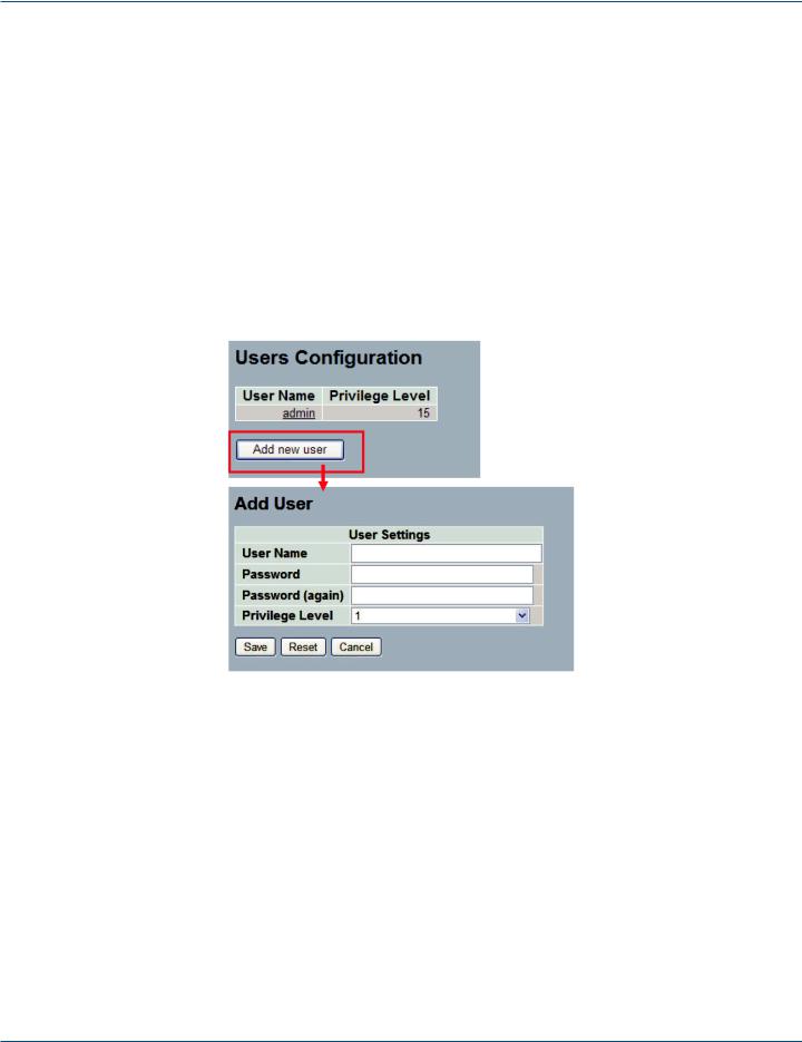
2.3.1 Users
This page provides an overview of the current users. Currently the only way to log in as another user on the Web server is to close and reopen the browser.
Web Interface
To configure Account in the Web interface:
1.Click SYSTEM, Account, Users.
2.Click Add new user
3.Specify the User Name parameter.
4.Click Save.
Figure 2-6. The Users Account configuration screen.
Parameter Description
•User Name: The name identifying the user. This is also a link to Add/Edit User.
•Password: To type the password. The specified string length is 0 to 255, and the specified content may include ASCII characters from 32 to 126.
•Password (again): To type the password again. You must type the same password again in the field.
•Privilege Level: The privilege level of the user. The range is 1 to 15. A privilege level value of 15 may access all groups, i.e. it is a privilege level that is granted the full control of the device. For other users, the privilege level should be the same as or greater than the group privilege level to have the access of that group. By default setting, most groups will have a privilege level 5, granting read-only access; a privilege level of 10 has the read-write access. For system maintenance (software uploads, factory defaults and etc.) users will need to have a user privilege level 15. Generally, the privilege level 15 can be used for an administrator account, privilege level 10 for a standard user account and privilege level 5 for a guest account.
Page 22 |
724-746-5500 | blackbox.com |
LPB2810A |
|
|
Chapter 2: System Configuration
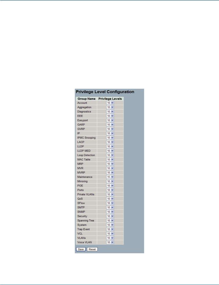
2.3.2 Privilege Levels
This section provides an overview of Privilege Levels. The switch enables administrators to set user privileges in a number of different categories, including Account, Aggregation, Diagnostics, EEE, GARP, GVRP, IP, IPMC, Snooping, LACP, LLDP, LLDP, MED, MAC, Table, MRP, MVR, MVRP, Maintenance, Mirroring, PoE, Ports, Private VLANs, QoS, SMTP, SNMP, Security, Spanning Tree, System, Trap Event ,VCL, VLANs, and Voice VLAN Privilege Levels from 1 to 15.
Web Interface
To configure Privilege Level in the Web interface:
1.Click SYSTEM, Account, Privilege Level.
2.Specify the Privilege parameter.
3.Click Save.
Figure 2-7. The Privilege Level Configuration screen.
LPB2810A |
724-746-5500 | blackbox.com |
Page 23 |
|
|

Chapter 2: System Configuration
Parameter Description
• Group Name
The name identifying the privilege group. In most cases, a privilege level group consists of a single module (e.g. LACP, RSTP or QoS), but a few of them contain more than one. The following description defines these privilege level groups in detail:
-System: Contact, Name, Location, Timezone, Log.
-Security: Authentication, System Access Management, Port (contains Dot1x port, MAC based and the MAC Address Limit), ACL, HTTPS, SSH, ARP Inspection and IP source guard.
-IP: Everything except 'ping'.
-Port: Everything except 'VeriPHY'.
-Diagnostics: 'ping' and 'VeriPHY'.
-Maintenance: System Reboot, System Restore Default, System Password, Configuration Save, Configuration Load and Firmware Load, Web users, Privilege Levels, and everything in Maintenance.
•Privilege Levels
Every group has an authorization Privilege Level for the following subgroups: configuration read-only; configuration/execute read-write; status/statistics read-only; status/statistics read-write (e.g. for clearing of statistics). User Privilege should be same or greater than the authorization Privilege level to have the access to that group.
Page 24 |
724-746-5500 | blackbox.com |
LPB2810A |
|
|
Chapter 2: System Configuration
2.4 IP (Internet Protocol)
IP is an acronym for Internet Protocol. It is a protocol used for communicating data across an Internet network.
IP is a "best effort" system, which means that no packet of information sent over is ensured to reach its destination in the same condition it was sent. Each device connected to a Local Area Network (LAN) or Wide Area Network (WAN) is given an Internet Protocol address, and this IP address is used to identify the device uniquely among all other devices connected to the extended network.
The current version of the Internet protocol is IPv4, which has 32-bits Internet Protocol addresses allowing for in excess of four billion unique addresses. This number is reduced drastically by the practice of Webmasters taking addresses in large blocks, the bulk of which remain unused. There is a rather substantial movement to adopt a new version of the Internet Protocol, IPv6, which would have 128-bits Internet Protocol addresses. This number can be represented roughly by a three with thirty-nine zeroes after it. However, IPv4 is still the protocol of choice for most of the Internet.
2.4.1 IPv4
The IPv4 address for the switch could be obtained via DHCP Server for VLAN 1. To manually configure an address, you need to change the switch's default settings to values that are compatible with your network. You may also need to a establish a default gateway between the switch and management stations that exist on another network segment.
Configure the switch-managed IP information on this page.
The Configured column is used to view or change the IP configuration.
The Current column is used to show the active IP configuration.
Web Interface
To configure an IP address in the Web interface:
1.Click System, IP Configuration.
2.Specify the IPv4 settings, and enable DNS proxy service if required.
3.Click Save.
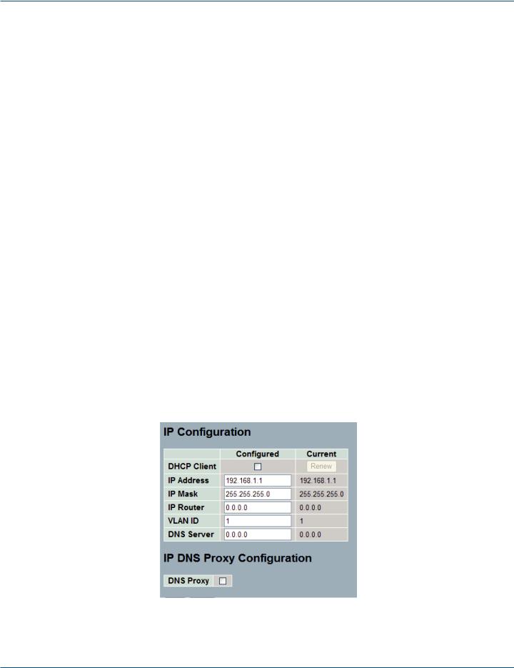
Figure 2-8. The IP Configuration screen.
LPB2810A |
724-746-5500 | blackbox.com |
Page 25 |
|
|

Chapter 2: System Configuration
Parameter Description
•DHCP Client: Enable the DHCP client by checking this box. If DHCP fails and the configured IP address is zero, DHCP will retry. If DHCP fails and the configured IP address is non-zero, DHCP will stop and the configured IP settings will be used. The DHCP client will announce the configured system name as hostname to provide DNS lookup.
•IP Address: Provide the IP address of this switch in dotted decimal notation.
•IP Mask: Provide the IP mask of this switch dotted decimal notation.
•IP Router: Provide the IP address of the router in dotted decimal notation.
•SNTP Server: Provide the IP address of the SNTP Server in dotted decimal notation.
•DNS Server: Provide the IP address of the DNS Server in dotted decimal notation.
•VLAN ID: Provide the managed VLAN ID. The permitted range is 1 to 4095.
•DNS Proxy: When DNS proxy is enabled, DUT will relay DNS requests to the current configured DNS server on DUT, and reply as a DNS resolver to the client device on the network.
Page 26 |
724-746-5500 | blackbox.com |
LPB2810A |
|
|
Chapter 2: System Configuration
2.4.2 IPV6
This section describes how to configure the switch-managed IPv6 information. The Configured column is used to view or change the IPv6 configuration. And the Current column is used to show the active IPv6 configuration.
Configure the switch-managed IPv6 information on this page.
The Configured column is used to view or change the IPv6 configuration.
The Current column is used to show the active IPv6 configuration.
Web Interface
To configure Management IPv6 of the switch in the Web interface:
1.Click System, IPv6 Configuration.
2.Specify the IPv6 settings, and enable Auto Configuration service if required.
3.Click Save.
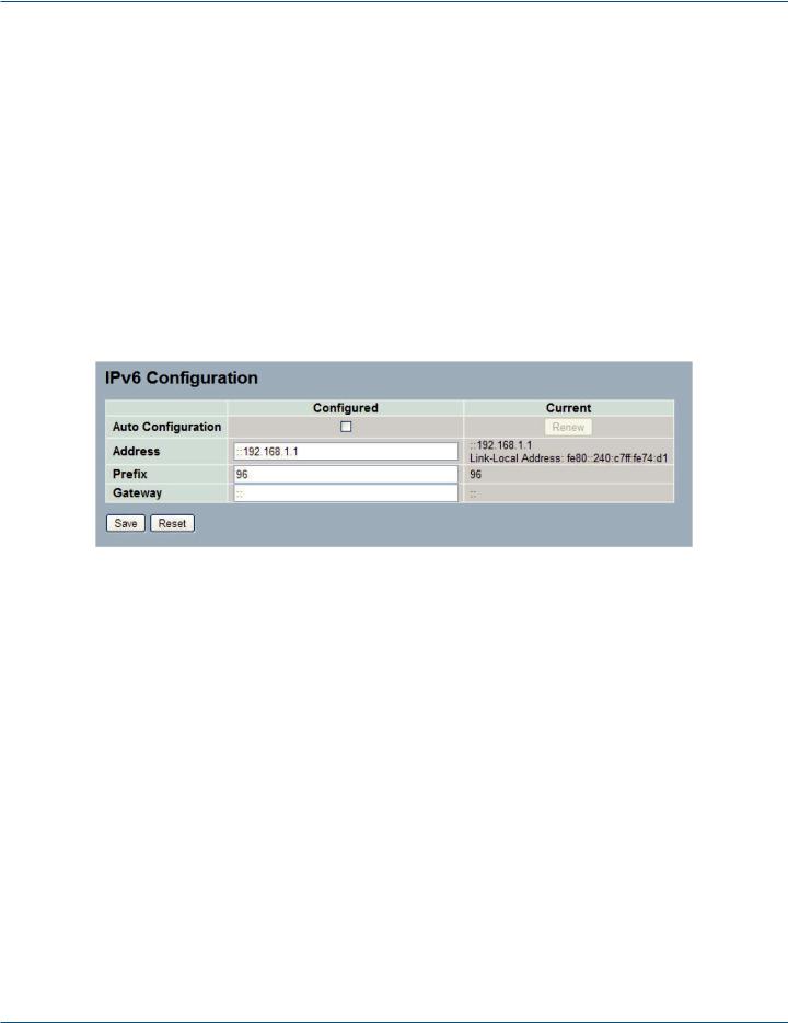
Figure 2-9. The IPv6 Configuration screen.
Parameter Description
•Auto Configuration: Enable IPv6 auto-configuration by checking this box. If fails, the configured IPv6 address is zero. The r outer may delay responding to a router solicitation for a few seconds, the total time needed to complete auto-configuration can be significantly longer.
•Address: Provide the IPv6 address of this switch. IPv6 address is represented in 128-bit records as eight fields of up to four hexadecimal digits with a colon separating each field (:). For example, in “fe80::215:c5ff:fe03:4dc7“, the symbol “::“ is a special syntax that can be used as a shorthand way of representing multiple 16-bit groups of contiguous zeros; but it can only appear once. It can also represent a legally valid IPv4 address. For example, “::192.1.2.34“.
•Prefix: Provide the IPv6 Prefix of this switch. The range is 1 to 128.
•Router: Provide the IPv6 gateway address of this switch. IPv6 address is represented in 128-bit records as eight fields of up to four hexadecimal digits with a colon separating each field (:). For example, in “fe80::215:c5ff:fe03:4dc7“, the symbol “::“ is a special syntax that can be used as a shorthand way of representing multiple 16-bit groups of contiguous zeros; but it can only appear once. It can also represent a legally valid IPv4 address. For example, “::192.1.2.34“.
LPB2810A |
724-746-5500 | blackbox.com |
Page 27 |
|
|
Chapter 2: System Configuration
2.5 Syslog
The Syslog (system log) is a standard for logging program messages. It allows separation of the software that generates messages from the system that stores them and the software that reports and analyzes them. It can also be used for generalized informational, analysis, and debugging messages. It is supported by a wide variety of devices and receivers across multiple platforms.
2.5.1 Configuration
This section describes how to configure the system log and provide a wide variety of devices and receivers across multiple platforms.
Web Interface
To configure syslog configuration in the Web interface:
1.Click SYSTEM, Syslog.
2.Specify the syslog parameters including the IP address of the Syslog server and the port number.
3.Evoke the syslog to enable it.
4.Click Save.
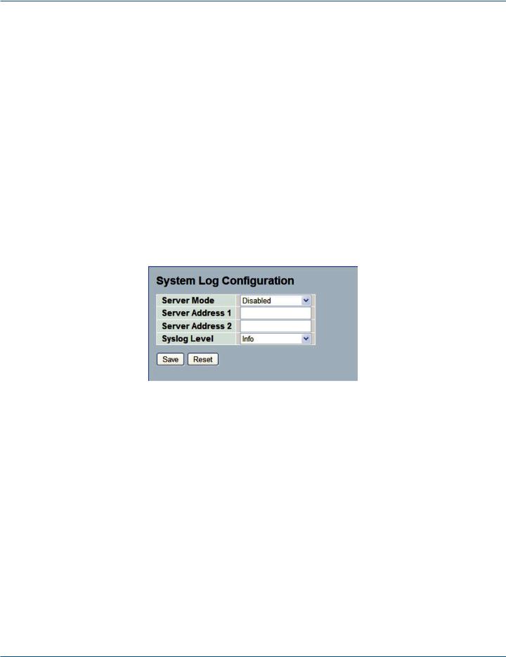
Figure 2-10. The System Log Configuration screen.
Parameter Description
•Server Mode: Indicates the server mode operation. When the mode operation is enabled, the syslog message will send out to syslog server. The syslog protocol is based on UDP communication and received on UDP Port 514. The syslog server will not send acknowledgments back to the sender since UDP is a connectionless protocol and it does not provide acknowledgments. The syslog packet will always be sent out even if the syslog server does not exist. Possible modes are:
-Enabled: Enable server mode operation.
-Disabled: Disable server mode operation.
•Server Address 1 and 2: Indicates the IPv4 host address of syslog server 1 and server 2 (for redundancy). If the switch provides a DNS feature, it also can be a host name.
•Syslog Level: Indicates what kind of message it will send to the syslog server. Possible modes are:
-Info: Send information, warnings, and errors.
-Warning: Send warnings and errors.
-Error: Send errors.
Page 28 |
724-746-5500 | blackbox.com |
LPB2810A |
|
|
Chapter 2: System Configuration
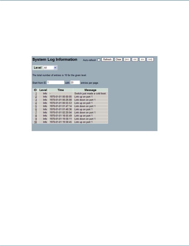
2.5.2 Log
This section describes how to display the System Log Information for the switch.
Web Interface
To display the log configuration in the Web interface:
1.Click Syslog, Log.
2.Display the log information.
Figure 2-11. The System Log Information screen.
Parameter Description
•Auto-refresh: To set the switch to auto-refresh the log information, check “Auto-refresh.”
•Level: level of the system log entry. The following level types are supported:
-Information level of the system log.
-Warning: Warning level of the system log.
-Error: Error level of the system log.
-All: All levels.
•ID: ID (>= 1) of the system log entry.
•Time: It will display the log record by device time. The time of the system log entry.
•Message: It will display the log detail message. The message of the system log entry.
•Icons, upper right of screen (Refresh, clear,….): Click these to refresh the system log or clear them manually. Arrow functions enable you to navigate to the first, prior, next, or last page.
LPB2810A |
724-746-5500 | blackbox.com |
Page 29 |
|
|
Chapter 2: System Configuration
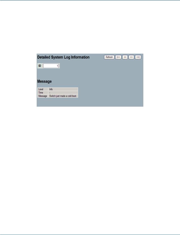
2.5.3 Detailed Log
This section describes how to use the Detailed Log Information for the switch.
Web Interface
To display the detailed log configuration in the Web interface:
1.Click Syslog, Detailed Log.
2.Display the log information.
Figure 2-12. The Detailed System Log Information screen.
Parameter Description
•ID: The ID (>= 1) of the system log entry.
•Message: The detailed message of the system log entry.
•Icons, upper right of screen (Refresh, clear, ….): Click to refresh the system log or to navigate to the first, prior, next, or last item.
Page 30 |
724-746-5500 | blackbox.com |
LPB2810A |
|
|
 Loading...