


LES421A
LES422A
LES424A
1-, 2-, and 4-Port Hardened Serial Servers
Connect serial RS-232/422/485 devices to Ethernet networks, allowing the serial device to become a node on the network.
Access the serial ports over a LAN/WAN using direct IP mode, virtual COM port, or paired mode connections.
Customer
Support
Information
Order toll-free in the U.S.: Call 877-877-BBOX (outside U.S. call 724-746-5500)
FREE technical support 24 hours a day, 7 days a week: Call 724-746-5500 or fax 724-746-0746 Mailing address: Black Box Corporation, 1000 Park Drive, Lawrence, PA 15055-1018
Web site: www.blackbox.com • E-mail: info@blackbox.com

Trademarks Used in this Manual
Trademarks Used in this Manual
Black Box and the Double Diamond logo are registered trademarks of BB Technologies, Inc. Firefox is a registered trademark of Mozilla Foundation.
Internet Explorer, Windows, and Windows Vista are registered trademarks of Microsoft Corporation. UL Is a registered trademark of Underwriters Laboratories.
Any other trademarks mentioned in this manual are acknowledged to be the property of the trademark owners.
We‘re here to help! If you have any questions about your application or our products, contact Black Box Tech Support at 724-746-5500 or go to blackbox.com and click on “Talk to Black Box.”
You’ll be live with one of our technical experts in less than 30 seconds.
Page 2 |
724-746-5500 | blackbox.com |

FCC and IC RFI Statements
Federal Communications Commission and Industry Canada Radio Frequency Interference
Statements
This equipment generates, uses, and can radiate radio-frequency energy, and if not installed and used properly, that is, in strict accordance with the manufacturer’s instructions, may cause interference to radio communication. It has been tested and found to comply with the limits for a Class A computing device in accordance with the specifications in Subpart B of Part 15 of FCC rules, which are designed to provide reasonable protection against such interference when the equipment is operated in a commercial environment. Operation of this equipment in a residential area is likely to cause interference, in which case the user at his own expense will be required to take whatever measures may be necessary to correct the interference.
Changes or modifications not expressly approved by the party responsible for compliance could void the user’s authority to operate the equipment.
This digital apparatus does not exceed the Class A limits for radio noise emission from digital apparatus set out in the Radio
Interference Regulation of Industry Canada.
Le présent appareil numérique n’émet pas de bruits radioélectriques dépassant les limites applicables aux appareils numériques de la classe A prescrites dans le Règlement sur le brouillage radioélectrique publié par Industrie Canada.
WARNING: EXPLOSION HAZARD—DO NOT DISCONNECT EQUIPMENT WHILE THE CIRCUIT IS LIVE OR UNLESS THE AREA IS KNOWN TO BE FREE OF IGNITABLE CONCENTRATIONS.
SUITABLE FOR USE IN CLASS I, DIVISION 2, GROUPS A, B, C AND D HAZARDOUS LOCATIONS, OR NONHAZARDOUS LOCATIONS ONLY.
WARNING: EXPLOSION HAZARD—SUBSTITUTION OF ANY COMPONENT MAY IMPAIR SUITABILITY FOR CLASS I, DIVISION 2.
724-746-5500 | blackbox.com |
Page 3 |

NOM Statement
Instrucciones de Seguridad
(Normas Oficiales Mexicanas Electrical Safety Statement)
1.Todas las instrucciones de seguridad y operación deberán ser leídas antes de que el aparato eléctrico sea operado.
2.Las instrucciones de seguridad y operación deberán ser guardadas para referencia futura.
3.Todas las advertencias en el aparato eléctrico y en sus instrucciones de operación deben ser respetadas.
4.Todas las instrucciones de operación y uso deben ser seguidas.
5.El aparato eléctrico no deberá ser usado cerca del agua—por ejemplo, cerca de la tina de baño, lavabo, sótano mojado o cerca de una alberca, etc.
6.El aparato eléctrico debe ser usado únicamente con carritos o pedestales que sean recomendados por el fabricante.
7.El aparato eléctrico debe ser montado a la pared o al techo sólo como sea recomendado por el fabricante.
8.Servicio—El usuario no debe intentar dar servicio al equipo eléctrico más allá a lo descrito en las instrucciones de operación. Todo otro servicio deberá ser referido a personal de servicio calificado.
9.El aparato eléctrico debe ser situado de tal manera que su posición no interfiera su uso. La colocación del aparato eléctrico sobre una cama, sofá, alfombra o superficie similar puede bloquea la ventilación, no se debe colocar en libreros o gabinetes que impidan el flujo de aire por los orificios de ventilación.
10.El equipo eléctrico deber ser situado fuera del alcance de fuentes de calor como radiadores, registros de calor, estufas u otros aparatos (incluyendo amplificadores) que producen calor.
11.El aparato eléctrico deberá ser connectado a una fuente de poder sólo del tipo descrito en el instructivo de operación, o como se indique en el aparato.
12.Precaución debe ser tomada de tal manera que la tierra fisica y la polarización del equipo no sea eliminada.
13.Los cables de la fuente de poder deben ser guiados de tal manera que no sean pisados ni pellizcados por objetos colocados sobre o contra ellos, poniendo particular atención a los contactos y receptáculos donde salen del aparato.
14.El equipo eléctrico debe ser limpiado únicamente de acuerdo a las recomendaciones del fabricante.
15.En caso de existir, una antena externa deberá ser localizada lejos de las lineas de energia.
16.El cable de corriente deberá ser desconectado del cuando el equipo no sea usado por un largo periodo de tiempo.
17.Cuidado debe ser tomado de tal manera que objectos liquidos no sean derramados sobre la cubierta u orificios de ventilación.
18.Servicio por personal calificado deberá ser provisto cuando:
A:El cable de poder o el contacto ha sido dañado; u
B:Objectos han caído o líquido ha sido derramado dentro del aparato; o
C:El aparato ha sido expuesto a la lluvia; o
D:El aparato parece no operar normalmente o muestra un cambio en su desempeño; o
E:El aparato ha sido tirado o su cubierta ha sido dañada.
Page 4 |
724-746-5500 | blackbox.com |

Table of Contents
Table of Contents
1. |
Specifications......................................................................................................................................................................... |
7 |
|
|
1.1 |
General.......................................................................................................................................................................... |
7 |
|
1.2 |
Serial Interface............................................................................................................................................................... |
7 |
|
1.3 |
Network......................................................................................................................................................................... |
8 |
|
1.4 |
TCP/UDP Ports............................................................................................................................................................... |
9 |
|
1.5 |
Dimensional Diagrams.................................................................................................................................................. |
10 |
2. |
Overview ............................................................................................................................................................................. |
12 |
|
|
2.1 |
Introduction................................................................................................................................................................. |
12 |
|
2.2 |
Features....................................................................................................................................................................... |
12 |
|
2.3 |
What’s Included........................................................................................................................................................... |
13 |
|
2.4 |
Hardware Description.................................................................................................................................................. |
13 |
|
|
2.4.1 1-Port Hardened Serial Server............................................................................................................................. |
13 |
|
|
2.4.2 2-Port Hardened Serial Server............................................................................................................................. |
14 |
|
|
2.4.3 4-Port Hardened Serial Server............................................................................................................................. |
15 |
|
2.5 |
Configuration Software................................................................................................................................................ |
16 |
3. Installation and Initial Setup................................................................................................................................................. |
17 |
||
|
3.1 |
Connecting the Power Supply...................................................................................................................................... |
17 |
|
3.2 |
Connecting Hardened Serial Servers to Serial Devices.................................................................................................. |
17 |
|
|
3.2.1 RS-232................................................................................................................................................................ |
17 |
|
|
3.2.2 RS-422................................................................................................................................................................ |
18 |
|
|
3.2.3 RS-485................................................................................................................................................................ |
18 |
|
3.3 |
Connecting Hardened Serial Servers to the Network................................................................................................... |
18 |
|
3.4 |
Ethernet Passthrough Port........................................................................................................................................... |
18 |
|
3.5 |
Hardened Serial Server Configuration.......................................................................................................................... |
19 |
|
|
3.5.1 Configuring via the Network using Hardened Serial Server Software................................................................. |
19 |
|
|
3.5.2 Configuring via the Network using a Browser.................................................................................................... |
19 |
|
|
3.5.3 Configuring via a Serial Port Using Hardened Serial Server Software (Console Mode)....................................... |
20 |
|
3.6 |
Hardened Serial Server Operational Connections......................................................................................................... |
20 |
|
3.7 |
Installing and Starting Hardened Serial Server Software.............................................................................................. |
21 |
|
3.8 |
Discovering Hardened Serial Servers............................................................................................................................ |
22 |
4. |
Configuring the Hardened Serial Server............................................................................................................................... |
23 |
|
|
4.1 |
Overview of the Hardened Serial Server Software....................................................................................................... |
23 |
|
|
4.1.1 Icons.................................................................................................................................................................... |
23 |
|
|
4.1.2 Hardened Serial Server Information Table........................................................................................................... |
24 |
|
|
4.1.3 Configuration Pane............................................................................................................................................. |
24 |
|
4.2 |
Logging In.................................................................................................................................................................... |
25 |
|
4.3 |
Navigating the Configuration Pages............................................................................................................................. |
25 |
|
4.4 |
Setting Up the Hardened Serial Server Name and Password........................................................................................ |
26 |
|
|
4.4.1 Changing the Hardened Serial Server’s Name..................................................................................................... |
26 |
|
|
4.4.2 Changing the Password...................................................................................................................................... |
26 |
|
4.5 |
Setting Up IP Addressing.............................................................................................................................................. |
26 |
|
|
4.5.1 Setting Up Dynamic IP Addressing...................................................................................................................... |
27 |
|
|
4.5.2 Setting Up Static IP Addressing........................................................................................................................... |
27 |
|
4.6 |
Setting Up Serial Ports................................................................................................................................................. |
28 |
|
4.7 |
Setting Up Port Network Parameters........................................................................................................................... |
28 |
|
|
4.7.1 TCP Configuration............................................................................................................................................... |
28 |
|
|
4.7.2 UDP Configuration.............................................................................................................................................. |
30 |
|
|
|
|
724-746-5500 | blackbox.com |
Page 5 |

Table of Contents
|
|
4.7.3 Setting Up Virtual COM (VCOM) Operation....................................................................................................... |
32 |
|
|
4.7.4 Setting Up Paired Mode Operation..................................................................................................................... |
32 |
|
4.8 |
Setting Up Advanced Network Settings....................................................................................................................... |
34 |
|
|
4.8.1 Configuring When Network Connections Will Be Forced Closed........................................................................ |
34 |
|
|
4.8.2 Configuring When Data Packets Are Sent.......................................................................................................... |
35 |
|
4.9 |
Saving/Restoring the Configuration Settings................................................................................................................ |
37 |
|
4.10 |
Adding Virtual COM Ports........................................................................................................................................... |
38 |
|
4.11 |
Removing Virtual COM Ports....................................................................................................................................... |
39 |
5. |
Upgrading the Hardened Serial Server Firmware................................................................................................................. |
40 |
|
|
5.1 |
Downloading Firmware Files........................................................................................................................................ |
40 |
|
5.2 |
Uploading the Firmware to the Hardened Serial Server............................................................................................... |
41 |
6. |
Operation............................................................................................................................................................................. |
42 |
|
|
6.1 |
LED Indicators.............................................................................................................................................................. |
42 |
|
6.2 |
Reset Switch................................................................................................................................................................. |
45 |
|
|
6.2.1 Using the Reset Switch to Initiate a Hardware Reset.......................................................................................... |
45 |
|
|
6.2.2 Using the Reset Switch to Enter Console Mode.................................................................................................. |
45 |
|
|
6.2.3 Using the Reset Switch to Exit Console Mode.................................................................................................... |
45 |
|
|
6.2.4 Using the Reset Switch to Reload Factory Default Settings................................................................................. |
45 |
7. |
Diagnostics........................................................................................................................................................................... |
46 |
|
|
7.1 |
Testing a Hardened Serial Server Connection............................................................................................................... |
46 |
|
7.2 |
Testing a Virtual COM Port.......................................................................................................................................... |
47 |
8. |
Listing/Descriptions of Hardened Serial Server Settings....................................................................................................... |
48 |
|
Appendix A. Default Server Settings.......................................................................................................................................... |
54 |
||
Appendix B. Connector Pinouts................................................................................................................................................. |
55 |
||
|
B.1 |
DB9 M Connector........................................................................................................................................................ |
55 |
|
B.2 |
Terminal Block.............................................................................................................................................................. |
55 |
|
B.3 |
Standard Ethernet Cable RJ-45 Pinout ........................................................................................................................ |
56 |
Page 6 |
724-746-5500 | blackbox.com |

Chapter 1: Specifications
1. Specifications
1.1 General
General Specifications
Certifications |
FCC Part 15, Class A, CE, NEMA TS2, UL® Class 1, Division 2, Groups A, B, C, and D |
Compatible Operating |
Windows® XP (32/64 bit), 2003 Server (32/64 bit), Windows Vista® (32/64 bit), 2008 Server (32/64 bit), Windows 7 (32/64 bit) |
Systems |
|
|
|
Configuration Options |
Via serial port using Hardened Serial Server Software, via network using Hardened Serial Server Software with an Ethernet connection |
|
or a standard Web browser such as Internet Explorer® 7, 8, or 9, or Firefox® 3 or 4 |
Enclosure |
Rating: IP30; |
|
Mounting: DIN rail mount (35 mm) |
|
|
User Controls |
(1) Reset button |
|
|
Connectors |
LES421A: (1) DB9 M, (1) 5-pin terminal block, (1) RJ-45, (1) 2-position pluggable terminal block for power; |
|
LES422A: (2) DB9 M, (1) RJ-45, (1) 2-position pluggable terminal block for power; |
|
LES424A: (4) DB9 M, (1) RJ-45, (1) 3-position pluggable terminal block and (1) locking barrel connector for power |
|
|
Indicators |
LES421A: (4) LEDs: (1) Ready, (1) Serial, (1) Ethernet Link, (1) Ethernet Speed; |
|
LES422A: (7) LEDs: (1) Ready, (2) Serial, (2) Ethernet Link, (2) Ethernet Speed; |
|
LES424A: (9) LEDs: (1) Ready, (4) Serial, (2) Ethernet Link, (2) Ethernet Speed |
|
|
Temperature Tolerance |
Operating: -40 to +176° F (-40 to +80° C); |
|
Storage: -40 to +185° F (-40 to +85° C); |
|
Maximum Ambient Surrounding Air Temperature: 176° F (80° C) |
|
|
Operating Humidity |
10 to 95%, noncondensing |
|
|
Power |
LES421A, LES422A: 10 to 48 VDC (58 VDC max.), 4.0 watts max.; |
|
LES424A: Locking barrel connector input: Voltage requirements: 10 to 30 VDC maximum, Class 2 grounded type supply only |
|
NOTE: Coaxial power cable must be in accordance with Class 2 requirements in Article 725 of the NEC. The locking barrel connector |
|
must not be used in a hazardous environment. |
|
LES424A (continued): Consumption: 6.0 watts maximum; |
|
Terminal blocks: Wire size: 28 to 16 AWG, |
|
Wire Type: Copper wire only, |
|
Tightening Torque: 5 kg-cm, |
|
Wire Temperature Rating: 105° C minimum, sized for 60° C ampacity |
|
NOTE: One conductor per terminal. |
|
|
Size |
LES421A, LES422A: 1.2"H x 3.2"W x 4.7"D (3 x 8.1 x 11.9 cm); |
|
LES424A: 1.8"H x 4.4"W x 6.8"D (4.6 x 12.2 x 17.1 cm) |
|
|
1.2 Serial Interface
Serial Interface Specifications
Baud Rates |
75, 150, 300, 600, 1200, 2400, 4800, 7200, 9600, 14400, 19200, 28800, 38400, 57600, 115200, 230400 |
|
|
|
|
Data Bits |
5, 6, 7, 8 |
|
|
|
|
Flow Control |
None, RTS/CTS, X-ON, X-OFF |
|
|
|
|
Mode Selection |
RS-232/422/485 software-selectable |
|
|
|
|
Parity |
|
None, even, odd, mark, space |
|
|
|
RS-232 Lines |
TXD, RXD, RTS, CTS, DTR, DSR, DCD, GND |
|
|
|
|
RS-422 Lines |
TXDA(-), TXDB(+), RXDA(-), RXDB (+), GND |
|
|
|
|
RS-485 |
(2-Wire) |
Data(-), Data(+), GND |
|
|
|
RS-485 |
(4-Wire) |
TXDA(-), TXDB(+), RXDA(-), RXDB (+), GND |
|
|
|
RS-422/485 Biasing |
Auto 1 K-ohm pullups and pulldowns |
|
|
|
|
RS-422/485 Termination |
Termination with through hole (user supplied) |
|
|
|
|
RS-485 |
Data Control |
Auto control via Data Multipoint Control Unit (MCU) |
|
|
|
Stop Bits |
1, 1.5, 2 |
|
|
|
|
724-746-5500 | blackbox.com |
Page 7 |

Chapter 1: Specifications
1.3 Network
Network Specifications
Character Count |
0 to 65535 |
|
|
Client Connection |
At power-up or upon data arrival |
|
|
Connection Modes |
Server, Client, VCOM, Paired |
|
|
Delimiters |
Hex 1 : 01 to FF (begin buffering when hex 1 received); |
|
Hex 2: 01 to FF (send serial data if delimiter hex 2 is set and received) |
|
|
Diagnostics |
DIsplay PC IP, ping, text VCOM, save test config (text readable) |
|
|
Memory |
Serial: 8 KB per port; |
|
Network memory: 4 KB |
|
|
Firmware Upgrade |
Via serial, Ethernet, or auto web search |
|
|
IP Port Addresses |
5300: heartbeat and configuration setting in TCP mode (i.e., Pair mode); |
|
8888: LES424A update |
|
|
Network |
LAN: 10-/100-Mbps auto-detecting 10BASE-T and 100BASE-TX |
Communications |
|
|
|
Network Physical |
Ethernet: IEEE 802.3 autodetecting and auto MDI/MDI-X 10BASE-T and 100BASE-TX |
Layer Standards |
|
|
|
Protocols Supported |
TCP, IPv4, UDP, ARP, HTTP 1.0, ICMP/PING, DHCP/BOOTP; |
|
IP mode: Static, DHCP; |
|
TCP/UDP: User-definable; |
|
UDP: Unicast or multicast |
|
|
Search |
Serial direct COM and Ethernet autosearch or specific IP |
|
|
Timeouts |
Inter-character: 0 to 65535 ms; |
|
Serial: 0 to 65535 ms; |
|
Network: 0 to 65535 min; |
|
Force transmit: 0 to 65535 ms; |
|
Max. character count: 0 to 8192 bytes |
|
|
Page 8 |
724-746-5500 | blackbox.com |
Chapter 1: Specifications
1.4 TCP/UDP Ports
Table 1-1. TCP/UDP ports.
Port
80/tcp
Description |
Comments |
This port is used for configuration of the device using a web browser.
This port is always open no matter how you configure the device.
Always open for the Web server. If you want to use this method to configure the device from outside of a firewall, then a firewall must allow incoming connections to this port.
If you want to use this method to configure the device from the outside of a NAT, the NAT must be configured to forward to this port.
This port is open when any serial 771/tcp port is configured for VCOM
mode.
This port is used for communications with the VCOM device driver installed on the computer. This port is open only if you configure any serial port for VCOM mode.
If you want to use VCOM from outside of a firewall, then you must allow incoming connections on this port.
If you want to use VCOM from outside of a NAT, then you must forward to this port.
7000/tcp |
Always open for serial server |
|
configuration over TCP. |
||
|
This port is used for configuration and firmware upgrade of the device using the serial server manager. This port is always open no matter how you configure the device.
If you want to configure the serial server from outside of a firewall using the serial server manager, then the firewall must be configured to allow incoming connections on 7000/tcp and allow packets addressed to 7000/udp to be received.
NOTE: Configuring over 7000/udp is not supported.
This port is open when serial 60000/tcp port 1 is configured for paired-
mode server.
These ports are used to transfer handshake line state and break state in paired mode configuration. These ports are open only if you configure the port for paired-mode server. Note that serial port 1 uses 60000/tcp, serial port 2 uses 60001/tcp, serial port 3 uses 60002/tcp, and serial port 4 uses 60003/tcp. If a port is not configured for paired-mode server, then the corresponding port is not open.
If you want to connect to a paired-mode server from outside of a firewall, then you must allow incoming connections on these ports.
If you want to connect to a paired-mode server from outside of a NAT, then you must forward to these ports.
|
This port is open when serial |
|
|
60001/tcp |
port 2 is configured for paired- |
As above |
|
mode server. Applies to LES422A |
|||
|
|
||
|
and LES424A only. |
|
|
|
|
|
|
|
This port is open when serial |
|
|
60002/tcp |
port 3 is configured for paired- |
As above |
|
mode server. Applies to LES424A |
|||
|
|
||
|
only. |
|
|
|
|
|
|
|
This port is open when serial |
|
|
60003/tcp |
port 4 is configured for paired- |
As above |
|
mode server. Applies to LES424A |
|||
|
|
||
|
only. |
|
|
|
|
|
|
|
This port is open when the |
This port is used if you configure the device for DHCP mode (as opposed to Static IP). It is used to |
|
68/udp |
communicate with the DHCP server. |
||
network mode is DHCP. |
|
||
|
This should only be used inside of a firewall or NAT. |
||
|
|
||
|
|
|
7000/udp |
Always open for serial server |
|
configuration over UDP. |
||
|
These ports are used for configuration and firmware upgrade of the device using the serial server manager. These ports are always open no matter how you configure the device.
If you want to configure the serial server from outside of a firewall using the serial server manager, then the firewall must be configured to allow incoming connections on 7000/tcp and allow packets addressed to 7000/udp to be received
|
|
|
This port is used for discovering serial servers. This port is always open no matter how you configure |
|
|
8899/udp |
Always open for serial server |
the device. |
|
|
discovery. |
NOTE: The device discovery only works on a local subnet. The port may not need to be configured |
|
|
|
|
|
||
|
|
|
|
|
|
|
|
in a firewall or NAT. |
|
|
|
|
|
|
|
|
|
Other TCP and UDP ports may be open, depending on what you specified for the device |
|
|
|
|
configuration. THESE ARE THE PORTS SPECIFIED IN THE CONFIGURATION FILE. |
|
|
Other |
User-specified ports. |
If you want to use these other ports from outside of a firewall, then you must allow these ports. |
|
|
|
|
|
|
|
|
|
If you want to use these other ports from outside of a NAT, then you must forward to these ports. |
|
|
|
|
|
|
|
|
|
|
|
724-746-5500 | blackbox.com |
Page 9 |

Chapter 1: Specifications
1.5 Dimensional Diagrams
Figure 1-1. Dimensional diagram of a LES421A or LES422A Hardened Serial Server (dimensions in inches).
Page 10 |
724-746-5500 | blackbox.com |
Chapter 1: Specifications
Figure 1-2. Dimensional diagram of a LES424A Hardened Serial Server (dimensions in inches and millimeters).
724-746-5500 | blackbox.com |
Page 11 |

Chapter 2: Overview
2. Overview
2.1 Introduction
The 1-, 2-, and 4-Port Hardened Serial Servers connect serial devices (RS-232, RS-422, or RS-485) to Ethernet networks, allowing the serial device to become a node on the network. The serial ports can be accessed over a LAN/WAN using Direct IP Mode, Virtual COM Port, or Paired Mode connections. Hardened Serial Servers use 10BASE-T or 100BASE-TX copper network media. All models also have an additional copper Ethernet pass-through port. Hardened Serial Servers are built for use in industrial environments and feature heavy duty metal enclosures that are paneland DIN-rail mountable. The product operates from a range of DC power supply voltages and features pluggable terminal block power connectors. The LES424A also has a locking barrel connector that facilitates redundant power sources.
Table 2-1. Available models.
|
Serial |
|
|
Ethernet |
Ethernet |
|
|
Part Number |
Ports |
Serial Connectors |
Ethernet Media |
Connector 1 |
Connector 2 |
Power |
|
|
|
|
|
|
|
|
|
|
|
(1) DB9M and (1) 5-pin terminal block |
|
|
|
|
|
LES421A |
1 |
NOTE: Use either the DB9 or the terminal |
RJ-45 |
RJ-45 |
— |
(1) 2-wire terminal block |
|
|
|
block connector, but not both at |
|
|
|
|
|
|
|
the same time. |
|
|
|
|
|
|
|
|
|
|
|
|
|
LES422A |
2 |
(2) DB9M |
RJ-45 |
RJ-45 |
— |
(1) 2-wire terminal block |
|
|
|
|
|
|
|
|
|
LES424A |
4 |
(4) DB9M |
RJ-45 |
RJ-45 |
RJ-45 |
(1) 3-wire terminal blockand (1) locking |
|
barrel connector for redundant power |
|||||||
|
|
|
|
|
|
||
|
|
|
|
|
|
|
2.2 Features
•LES421A, LES422A: single Ethernet connector.
•LES424A: (2) Ethernet connectors (Ethernet passthrough ports).
•Multi-interface serial ports (RS-232, RS-422, RS-485).
•LES421A has DB9M and pluggable terminal block serial port connector options.
•LES422A and LES424A have DB9M serial port connectors.
•All serial ports are software selectable for RS-232, RS-422, or RS-485 2- and 4-wire communication.
•Configuration can be done via network or direct serial connection.
•Rugged metal case; DIN rail or panel mountable.
•Accepts DC power over a wide voltage range.
•LES424A has two power connections (pluggable terminal strip and locking barrel connector), which can be used for a redundant power supply.
•Supports 10-/100-Mbps Ethernet with auto-selection.
•Configurable for TCP Client or Server, or UDP operation.
•Virtual COM port and Paired Mode capabilities.
•Upload firmware over the Ethernet port for future revisions/upgrades.
•Supports Windows XP (32/64 bit), 2003 Server (32/64 bit), Vista (32/64 bit), 2008 Server (32/64 bit), Windows 7 (32/64 bit).
•Configure Ethernet and serial port settings using Hardened Serial Server Software or built-in Web server.
Page 12 |
724-746-5500 | blackbox.com |
Chapter 2: Overview
2.3 What‘s Included
Your package should include the following items. If anything is missing or damaged, contact Black Box Technical Support at 724-746-5500 or info@blackbox.com.
LES421A or LES422A:
•1- or 2-port Hardened Serial Server module.
•A printed quick start guide.
•This user manual in PDF format on CD-ROM
LES424A:
•4-port Hardened Serial Server module.
•A printed quick start guide.
•This user manual in PDF format on CD-ROM
•(1) 3-position terminal block Phoenix connector
•(1) Panel mount kit: (2) brackets, (4) screws
•(1) DIN rail mounting kit: (1) DIN rail bracket, (3) screws
NOTE: To download this user manual, go to ftp://ftp.blackbox.com/anonymous/manuals/L/LES421A_2A_4A_USER_rev1.pdf or visit the Black Box Web site (www.blackbox.com) and enter LES421A, LES422A, or LES424A in the search bar.
2.4 Hardware Description
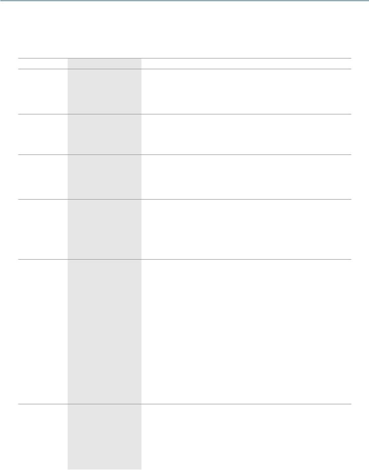
2.4.1 1-Port Hardened Serial Server (LES421A)
Figures 2-1 and 2-2 show the front and top panels of the LES421A. Table 2-2 describes its components.
5 |
|
|
7 |
4 |
||
|
||||||
6 |
||||||
|
|
|||||
1 |
|
|
|
|
8 |
|
|
|
|
|
|||
|
|
|
|
|
||
2 |
|
|
|
|
|
|
|
|
|
|
|
||
3
Figures 2-1 and 2-2. LES421A front and top panels.
724-746-5500 | blackbox.com |
Page 13 |
Chapter 2: Overview
Table 2-2. LES421A components.
Number in Figure |
|
|
|
|
2-1 or 2-2 |
Component |
Description |
||
|
|
|
|
|
1 |
(1) |
RJ-45 connector |
Connects a standard Ethernet network drop using a straight-through RJ-45 male Ethernet cable. |
|
|
|
|
|
|
2 |
(1) |
5-position terminal block connector |
Connects to an RS-422 or RS-485 serial device when the DB9 M (RS-232) connector is disabled. |
|
|
|
|
|
|
3 |
(1) |
DB9 male connector |
Connects to an RS-232 serial device when the 5-position terminal block (RS-422/RS-485) is disabled. |
|
|
|
|
|
|
4 |
(1) |
2-wire terminal block connector |
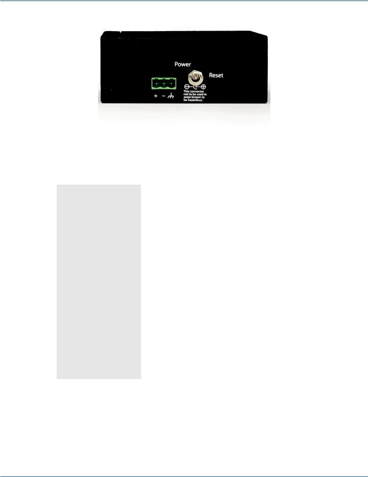
Removable 2-position terminal block with +, -, and chassis ground connections. |
|
|
|
|
|
|
5 |
(1) |
Serial Port LED |
Flashes green when data is being transmitted or received on the serial port. |
|
Lights steady green when the serial port is open. |
||||
|
|
|
||
|
|
|
|
|
6 |
(1) |
Ethernet Link LED |
Lights when a connection is made. |
|
Flashes when there is data traffic on the Ethernet link. |
||||
|
|
|
||
|
|
|
|
|
|
|
|
Lights green continuously when the unit is initializing. |
|
7 |
(1) |
Ready LED |
Flashes once per second when the system is operating correctly. |
|
|
|
|
Off when something is wrong, for example, another device uses the same IP address. |
|
|
|
|
|
|
8 |
(1) |
Reset button |
Used to initiate a hardware reset, enter console mode, or reload factory defaults. |
|
|
|
|
|
|
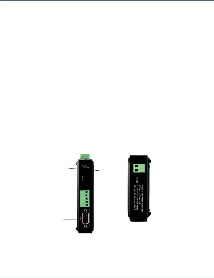
2.4.2 2-Port Hardened Serial Server (LES422A)
Figures 2-3 and 2-4 show the front and top panels of the LES422A. Table 2-3 describes its components.
4 |
|
|
7 |
3 |
||
|
||||||
6 |
||||||
4 |
|
|||||
|
|
|
|
|
||
1 |
|
|
|
|
7 |
|
|
|
|
|
|||
|
|
|
|
|
||
2 |
|
|
|
|
|
|
|
|
|
|
|
||
2
Figures 2-3 and 2-4. LES422A front and top panels.
Page 14 |
724-746-5500 | blackbox.com |
Chapter 2: Overview
|
|
|
Table 2-3. LES422A components. |
|
|
|
|
|
|
Number in Figure |
|
|
|
|
2-3 or 2-4 |
Component |
Description |
||
|
|
|
|
|
1 |
(1) |
RJ-45 connector |
Connects a standard Ethernet network drop using a straight-through RJ-45 male Ethernet cable. |
|
|
|
|
||
2 |
(2) DB9 male connectors |
Connects to RS-232, RS-422, or RS-485 serial devices. |
||
|
|
|
|
|
3 |
(1) |
2-wire terminal block connector |
Removable 2-position terminal block with +, -, and chassis ground connections. |
|
|
|
|
|
|
4 |
(2) Serial Port LEDs |
Flashes green when data is being transmitted or received on the serial port. |
||
Lights steady green when the serial port is open. |
||||
|
|
|
||
|
|
|
|
|
5 |
(1) |
Ethernet Link LED |
Lights when a connection is made. |
|
Flashes when there is data traffic on the Ethernet link. |
||||
|
|
|
||
|
|
|
|
|
|
|
|
Lights green continuously when the unit is initializing. |
|
6 |
(1) |
Ready LED |
Flashes once per second when the system is operating correctly. |
|
|
|
|
Off when something is wrong, for example, another device uses the same IP address. |
|
|
|
|
|
|
7 |
(1) |
Reset button |
Used to initiate a hardware reset, enter console mode, or reload factory defaults. |
|
|
|
|
|
|
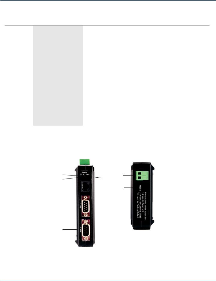
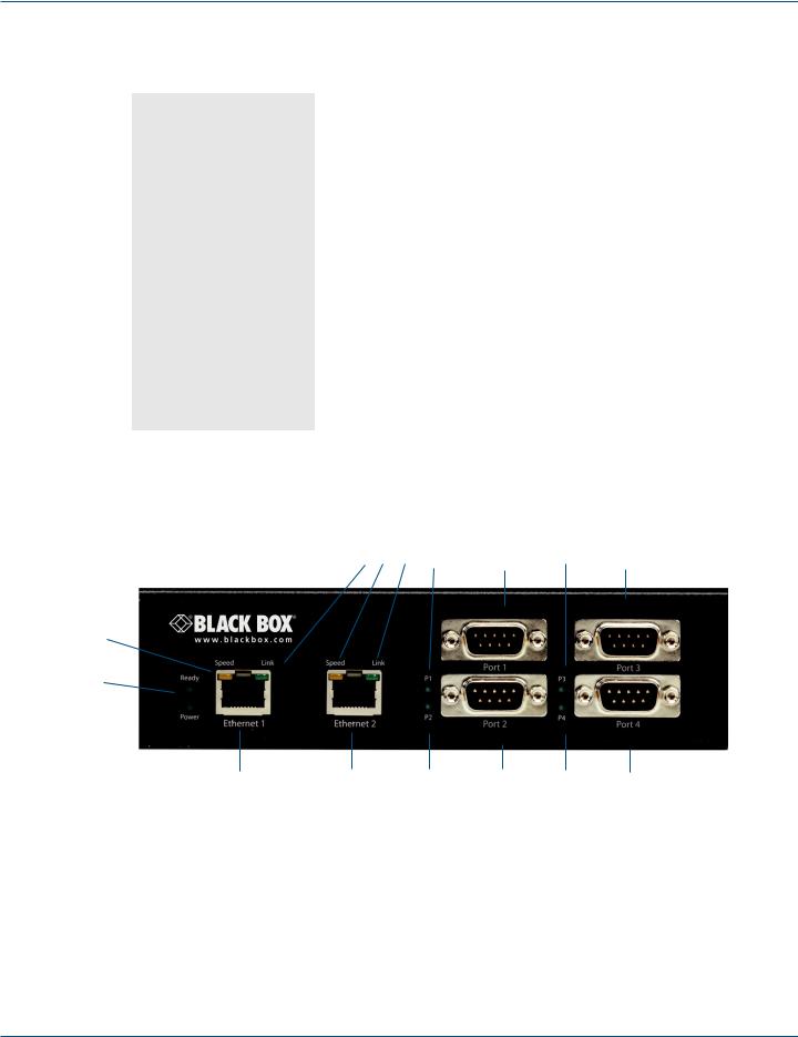
2.4.3 4-Port Hardened Serial Server (LES424A)
Figures 2-5 and 2-6 show the front and side panels of the LES424A. Table 2-4 describes its components.
4 |
3 |
4 |
5 |
6 |
5 |
6 |
3
2
1 
7 |
7 |
5 |
6 |
5 |
6 |
|
Figure 2-5. LES424A front panel. |
|
|
||
724-746-5500 | blackbox.com |
Page 15 |
Chapter 2: Overview
|
|
|
|
|
|
|
|
|
|
|
|
|
|
|
|
8 |
9 |
|||
|
|
Figure 2-6. LES424A back panel. |
||||
|
|
Table 2-4. LES424A components. |
||||
|
|
|
|
|
|
|
Number in Figure |
|
|
|
|
|
|
2-5 or 2-6 |
Component |
Description |
|
|
||
|
|
|
|
|
||
1 |
(1) Power LED |
Lights when power to the unit is on. |
||||
|
|
|
|
|
||
|
|
Lights green continuously when the unit is initializing. |
||||
2 |
(1) Ready LED |
Flashes once per second when the system is operating correctly. |
||||
|
|
Off when something is wrong, for example, another device uses the same IP address. |
||||
|
|
|
|
|
||
3 |
(2) Ethernet Speed LEDs |
Lights green when the Ethernet connection is operating at 100 Mbps. |
||||
Off when the connection is operating at 10 Mbps. |
||||||
|
|
|||||
|
|
|
|
|
||
4 |
(2) Ethernet Link LEDs |
Lights when a connection is made. |
||||
Flashes when there is data traffic on the Ethernet link. |
||||||
|
|
|||||
|
|
|
|
|
||
5 |
(4) Serial Port LEDs |
Flashes green when data is being transmitted or received on the serial port. |
||||
Lights steady green when the serial port is open. |
||||||
|
|
|||||
|
|
|
|
|
||
6 |
(4) DB9 male connectors |
Connects to RS-232, RS-422, or RS-485 serial devices. |
||||
|
|
|
|
|
||
7 |
(2) RJ-45 connectors |
Enable the server to act as an Ethernet switch. |
||||
|
|
|
|
|
||
8 |
(1) 3-wire terminal block connector |
Removable 3-position terminal block with +, -, and chassis ground connections. |
||||
|
|
|
|
|
||
9 |
(1) Reset button |
Used to initiate a hardware reset, enter console mode, or reload factory defaults. |
||||
|
|
|
|
|
|
|
2.5 Configuration Software
Manager configuration software enables you to find connected Hardened Serial Servers, configure them, upgrade Hardened Serial Server firmware, and save/load configuration files. It features a graphical user interface (GUI) that is convenient and easy to use. The software also makes it easy to add and remove virtual COM ports on your computer.
Page 16 |
724-746-5500 | blackbox.com |
Chapter 3: Installation and Setup
3. Installation and Initial Setup
This section describes how to install the Hardened Serial Server and configure the device.
NOTE: In this section, devices to be connected to the Hardened Serial Server’s serial connections are simply referred to as the “serial device.”
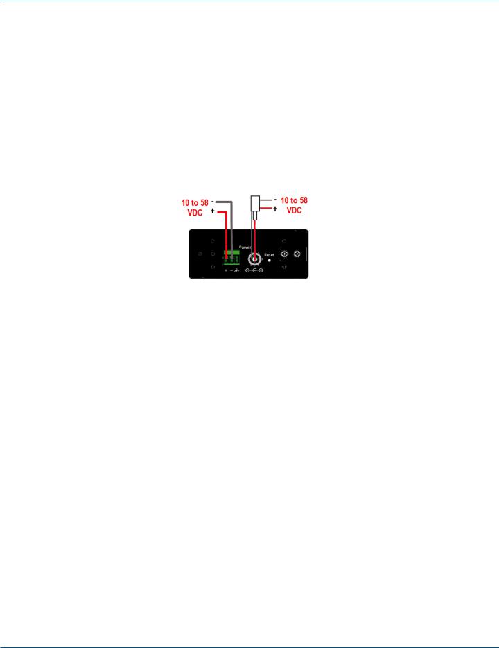
3.1 Connecting the Power Supply
Connect a DC power supply to the power terminals on the side of the Hardened Serial Server. Polarity of the wires is indicated underneath each connector. Acceptable voltages are between 10 VDC and 58 VDC. The power supply must be capable of supplying 4 watts for the LES421A or LES422A or 6 watts for the LES424A.
Figure 3-1. LES421A, LES422A, and LES424A power supply connections.
3.2 Connecting Hardened Serial Servers to Serial Devices
The Hardened Serial Servers can be connected to serial devices using RS-232, RS-422, RS-485 2-wire, or RS-485 4-wire communication. LES422A and LES424A models use (2) or (4) DB9 M connectors. LES421A models use either (1) DB9 M connector or (1) 5-position terminal strip.
3.2.1 RS-232
The 2- and 4-port models, along with the 1-port model when using its DB9M connector, support seven RS-232 signal lines (TD, RD, DTR, DSR, RTS, CTS, DCD) plus Signal Ground.
The 1-port model, when using its 5-position pluggable terminal block, supports four signal lines (TD, RD, RTS, CTS) plus Signal Ground.
NOTE: Only one connector (DB9M or 5-position terminal block) can be used on the LES421A.
Signals are single-ended and referenced to Signal Ground. Default communications parameters are 9600, 8, N, 1 (9600 baud, 8 data bits, no parity, 1 stop bit), and no flow control.
NOTE: The LES421A, LES422A, and LES424A are configured as DTEs. If they are connected to a computer or other DTE device, use a null-modem (crossover) cable. If the serial device is configured as a DCE, use a straight-through cable.
724-746-5500 | blackbox.com |
Page 17 |
Chapter 3: Installation and Setup
3.2.2 RS-422
RS-422 connections support two signal pairs: TDA (-), TDB (+), RDA (-), RDB (+), and GND. The data lines are differential pairs (A and B) in which the B line is positive relative to the A line in the idle (mark) state. In RS-422, the transmitter is always enabled. Signal Ground provides a common mode reference for the signal lines.
3.2.3 RS-485
RS-485 connections support 2-wire or 4-wire operation. In RS-485 mode, the transmitter is only enabled when the Hardened Serial Server is transmitting data on the line. This allows other devices to share the bus.
When configured for 4-wire operation, the connection supports two signal pairs: TDA (-), TDB (+), RDA (-), RDB (+), and GND. This makes full-duplex operation possible. The data lines are differential pairs (A and B) in which the B line is positive relative to the A line in the idle (mark) state. Signal Ground provides a common mode reference for the signal lines.
When configured for 2-wire operation, the connection supports one signal pair: Data A (-) and Data B (+). These lines transmit and receive signals using half-duplex operation. The data lines are differential with the Data B line positive relative to Data A in the idle (mark) state. Signal Ground provides a common mode reference for the signal lines.
NOTE: Refer to Appendix B for connector pinout information.
Network
Serial connection |
Serial device |
|
Figure 3-2. LES424A connections.
3.3 Connecting RS-232/422/485 Hardened Serial Servers to a Network
Ethernet Connection (10BASE-T/100BASE-TX)
When connecting a Hardened Serial Server equipped with a 10BASE-T/100BASE-TX network connection (RJ-45 connector) to an Ethernet network, use a standard unshielded twisted-pair cable. When installing this equipment in industrial or other electrically noisy environments, we strongly recommend that you use STP (shielded twisted pair) cable. The Hardened Serial Server has an automatic MDI-X interface that will sense the pinout of the network interface and provide a crossover connection if required.
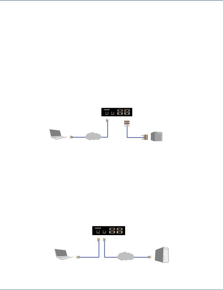
3.4 Ethernet Passthrough Port
4-Port Hardened Serial Servers (LES424A) are equipped with an additional RJ-45 network port, also known as a passthrough port. This port can be used to connect additional Ethernet devices, such as a local workstation or second serial server, to the network.
Local Ethernet
device
Network
Figure 3-3. Ethernet passthrough port (on LES424A only).
Page 18 |
724-746-5500 | blackbox.com |
 Loading...