


 Loading...
Black Box LES1332A, LES1408A, LES114BA, LES1208A-R2, LES1132A User Manual
...
|
|
|
LES1108A |
LES1208A-R2 |
LES1308A |
LES1408A |
LES1508A |
|
|
|
|
|
LES1116A |
LES1216A-R2 |
LES1316A |
LES1416A |
|
|
|
|
|
LES1132A |
LES1232A |
LES1332A |
LES1432A |
|
|
|
|
|
LES1148A |
LES1248A-R2 |
LES1348A |
LES1448A |
|
|
|
|
|
|
|
|
|
|
|
|
|
|
|
|
|
|
|
|
|
|
|
|
|
|
|
|
Value-Line and Advanced Console Servers User’s Manual
Securely manage data center and network equipment from anywhere in the world.
Customer
Support
Information
Order toll-free in the U.S.: Call 877-877-BBOX (outside U.S. call 724-746-5500)
FREE technical support 24 hours a day, 7 days a week: Call 724-746-5500 or fax 724-746-0746 Mailing address: Black Box Corporation, 1000 Park Drive, Lawrence, PA 15055-1018
Web site: www.blackbox.com • E-mail: info@blackbox.com

Value-Line and Advanced Console Servers Manual
Trademarks Used in this Manual
Black Box and the Double Diamond logo are registered trademarks of BB Technologies, Inc.
Cisco is a registered trademark of Cisco Technology, Inc.
Mac is a registered trademark of Apple Computers, Inc.
Linux is a registered trademark of Linus Torvalds.
Internet Explorer, Windows, Windows Me, Windows NT, and Windows Vista are a registered trademarks of Microsoft Corporation. Nagios is a registered trademark of Nagios Enterprises LLC.
Java and Solaris are trademarks of Sun Microsystems, Inc.
Unix is a registered trademark of X/Open Company Ltd.
Any other trademarks mentioned in this manual are acknowledged to be the property of the trademark owners.
Page 2 |
724-746-5500 | blackbox.com |

Value-Line and Advanced Console Servers Manual
We‘re here to help! If you have any questions about your application or our products, contact Black Box Tech Support at 724-746-5500 or go to blackbox.com and click on “Talk to Black Box.”
You’ll be live with one of our technical experts in less than 30 seconds.
724-746-5500 | blackbox.com |
Page 3 |

Value-Line and Advanced Console Servers Manual
Federal Communications Commission and Industry Canada Radio Frequency Interference
Statements
This equipment generates, uses, and can radiate radio-frequency energy, and if not installed and used properly, that is, in strict accordance with the manufacturer’s instructions, may cause interference to radio communication. It has been tested and found to comply with the limits for a Class A computing device in accordance with the specifications in Subpart B of Part 15 of FCC rules, which are designed to provide reasonable protection against such interference when the equipment is operated in a commercial environment. Operation of this equipment in a residential area is likely to cause interference, in which case the user at his own expense will be required to take whatever measures may be necessary to correct the interference.
Changes or modifications not expressly approved by the party responsible for compliance could void the user’s authority to operate the equipment.
This digital apparatus does not exceed the Class A limits for radio noise emission from digital apparatus set out in the Radio
Interference Regulation of Industry Canada.
Le présent appareil numérique n’émet pas de bruits radioélectriques dépassant les limites applicables aux appareils numériques de la classe A prescrites dans le Règlement sur le brouillage radioélectrique publié par Industrie Canada.
Page 4 |
724-746-5500 | blackbox.com |

Value-Line and Advanced Console Servers Manual
Instrucciones de Seguridad
(Normas Oficiales Mexicanas Electrical Safety Statement)
1.Todas las instrucciones de seguridad y operación deberán ser leídas antes de que el aparato eléctrico sea operado.
2.Las instrucciones de seguridad y operación deberán ser guardadas para referencia futura.
3.Todas las advertencias en el aparato eléctrico y en sus instrucciones de operación deben ser respetadas.
4.Todas las instrucciones de operación y uso deben ser seguidas.
5.El aparato eléctrico no deberá ser usado cerca del agua—por ejemplo, cerca de la tina de baño, lavabo, sótano mojado o cerca de una alberca, etc..
6.El aparato eléctrico debe ser usado únicamente con carritos o pedestales que sean recomendados por el fabricante.
7.El aparato eléctrico debe ser montado a la pared o al techo sólo como sea recomendado por el fabricante.
8.Servicio—El usuario no debe intentar dar servicio al equipo eléctrico más allá a lo descrito en las instrucciones de operación. Todo otro servicio deberá ser referido a personal de servicio calificado.
9.El aparato eléctrico debe ser situado de tal manera que su posición no interfiera su uso. La colocación del aparato eléctrico sobre una cama, sofá, alfombra o superficie similar puede bloquea la ventilación, no se debe colocar en libreros o gabinetes que impidan el flujo de aire por los orificios de ventilación.
10.El equipo eléctrico deber ser situado fuera del alcance de fuentes de calor como radiadores, registros de calor, estufas u otros aparatos (incluyendo amplificadores) que producen calor.
11.El aparato eléctrico deberá ser connectado a una fuente de poder sólo del tipo descrito en el instructivo de operación, o como se indique en el aparato.
12.Precaución debe ser tomada de tal manera que la tierra fisica y la polarización del equipo no sea eliminada.
13.Los cables de la fuente de poder deben ser guiados de tal manera que no sean pisados ni pellizcados por objetos colocados sobre o contra ellos, poniendo particular atención a los contactos y receptáculos donde salen del aparato.
14.El equipo eléctrico debe ser limpiado únicamente de acuerdo a las recomendaciones del fabricante.
15.En caso de existir, una antena externa deberá ser localizada lejos de las lineas de energia.
16.El cable de corriente deberá ser desconectado del cuando el equipo no sea usado por un largo periodo de tiempo.
17.Cuidado debe ser tomado de tal manera que objectos liquidos no sean derramados sobre la cubierta u orificios de ventilación.
18.Servicio por personal calificado deberá ser provisto cuando:
A:El cable de poder o el contacto ha sido dañado; u
B:Objectos han caído o líquido ha sido derramado dentro del aparato; o
C:El aparato ha sido expuesto a la lluvia; o
D:El aparato parece no operar normalmente o muestra un cambio en su desempeño; o
E:El aparato ha sido tirado o su cubierta ha sido dañada.
724-746-5500 | blackbox.com |
Page 5 |
INDEX
INTRODUCTION |
13 |
|
INSTALLATION |
18 |
|
2.1 |
Models |
18 |
2.1.1 |
Kit components LES1508A Console Server |
19 |
2.1.2 |
Kit components LES1308ALES1348A and LES1408A - LES1448A Advanced Console Servers |
19 |
2.1.3 |
Kit components LES1208A-R2, LES1216A-R2, LES1232A and LES1248A-R2 Advanced Console Servers |
20 |
2.1.4 |
Kit components LES1116A, LES1132A and LES1148A Console Servers |
21 |
2.1.5 |
Kit components LES1108A Console Server |
21 |
2.2 |
Power connection |
21 |
2.2.1 |
LES1508A power |
21 |
2.2.2 |
LES1408A - LES1448A, LES1308ALES1348A and LES1208A - LES1248A power |
22 |
2.2.2 |
LES1116A, LES1132A and LES1148A power |
22 |
2.2.4 |
LES1108A power |
23 |
2.3 |
Network connection |
23 |
2.4 |
Serial Port connection |
23 |
2.5 |
USB Port Connection |
24 |
2.6 |
Antenna and SIM |
25 |
SYSTEM CONFIGURATION |
26 |
|
3.1 |
Management console connection |
26 |
3.1.1 |
Connected PC/workstation set up |
26 |
3.1.2 |
Browser connection |
27 |
3.2 |
Administrator Password |
29 |
3.2.1 |
Set up new administrator |
30 |
3.2.2 |
Name the console server |
30 |
3.3 |
Network IP address |
30 |
3.3.1 |
IPv6 configuration |
32 |
3.3.2 |
Dynamic DNS (DDNS) configuration |
32 |
3.4 |
System Services |
33 |
3.4.1 |
Service Access |
33 |
3.4.2 |
Service Settings |
35 |
3.5 |
Communications Software |
36 |
3.5.1 |
SDT Connector |
37 |
3.5.2 |
PuTTY |
37 |
3.5.3 |
SSHTerm |
38 |
3.6 |
Management network configuration |
38 |
3.6.1 |
Enable the Management LAN |
39 |
3.6.2 |
Configure the DHCP server |
40 |
3.6.3 |
Select Failover or broadband OOB |
41 |
3.6.4 |
Aggregating the network ports |
43 |
3.6.5 |
Static routes |
44 |
SERIAL PORT AND NETWORK HOST |
46 |
|
4.1 |
Configure Serial Ports |
46 |
4.1.1 |
Common Settings |
47 |
4.1.2 |
Console Server Mode |
48 |
4.1.3 |
SDT Mode |
53 |
4.1.4 |
Device (RPC, UPS, EMD) Mode |
54 |
4.1.5 |
Terminal Server Mode |
54 |
4.1.6 |
Serial Bridging Mode |
55 |
4.1.7Syslog 55
_____________________________________________________________________
724-746-5500 | blackbox.com |
Page 6 |
4.1.8 |
Cisco USB console connection |
56 |
4.2 |
Add/ Edit Users |
56 |
4.3 |
Authentication |
60 |
4.4 |
Network Hosts |
60 |
4.5 |
Trusted Networks |
61 |
4.6 |
Serial Port Cascading |
62 |
4.6.1 |
Automatically generate and upload SSH keys |
62 |
4.6.2 |
Manually generate and upload SSH keys |
63 |
4.6.3 |
Configure the slaves and their serial ports |
65 |
4.6.4 |
Managing the Slaves |
66 |
4.7 |
Serial Port Redirection |
66 |
4.8 |
Managed Devices |
67 |
4.9 |
IPsec VPN |
69 |
4.9.1 |
Enable the VPN gateway |
70 |
4.10 |
OpenVPN |
71 |
4.10.1 |
Enable the OpenVPN |
71 |
4.10.2 |
Configure as Server or Client |
72 |
4.10.3 |
Windows OpenVPN Client and Server set up |
73 |
4.11 |
PPTP VPN |
77 |
4.11.1 |
Enable the PPTP VPN server |
77 |
4.11.2 |
Add a PPTP user |
79 |
4.11.3 |
Set up a remote PPTP client |
79 |
FIREWALL, FAILOVER AND OoB DIAL-IN |
81 |
|
5.1 |
OoB Dial-In Access |
81 |
5.1.1 |
Configure Dial-In PPP |
82 |
5.1.2 |
Using SDT Connector client |
84 |
5.1.3 |
Set up Windows XP/ 2003/Vista/7 client |
84 |
5.1.4 |
Set up earlier Windows clients |
85 |
5.1.5 |
Set up Linux clients for dial-in |
85 |
5.2 |
OoB broadband access |
85 |
5.3 |
Broadband Ethernet Failover |
86 |
5.4 |
Dial-Out Failover |
87 |
5.4.1 |
Always-on dial-out |
87 |
5.4.2 |
Failover dial-out |
89 |
5.5 |
Cellular Modem Connection |
89 |
5.6.1 |
Connect to the GSM HSUPA/UMTS carrier network |
89 |
5.6.2 |
Connect to the CDMA EV-DO carrier network |
91 |
5.6.3 |
Verify cellular connection |
92 |
5.6.4 |
Cellular modem watchdog |
92 |
5.7 |
Cellular Operation |
93 |
5.7.1 |
OOB access set up |
93 |
5.7.2 |
Cellular failover setup |
93 |
5.7.3 |
Cellular routing |
94 |
5.7.4 |
Cellular CSD dial-in setup |
94 |
5.8 |
Firewall & Forwarding |
95 |
5.8.1 |
Configuring network forwarding and IP masquerading |
96 |
5.8.2 |
Configuring client devices |
97 |
5.8.3 |
Port forwarding |
98 |
5.8.4 |
Firewall rules |
99 |
SECURE SSH TUNNELING AND SDT CONNECTOR |
102 |
|
6.1 |
Configuring for SSH Tunneling to Hosts |
103 |
6.2 |
SDT Connector Client Configuration |
103 |
_____________________________________________________________________
724-746-5500 | blackbox.com Page 7
6.2.1 |
SDT Connector installation |
104 |
6.2.2 |
Configuring a new console server gateway in the SDT Connector client |
105 |
6.2.3 |
Auto-configure SDT Connector client with the user’s access privileges |
106 |
6.2.4 |
Make an SDT connection through the gateway to a host |
107 |
6.2.5 |
Manually adding hosts to the SDT Connector gateway |
108 |
6.2.6 |
Manually adding new services to the new hosts |
109 |
6.2.7 |
Adding a client program to be started for the new service |
111 |
6.2.8 |
Dial in configuration |
113 |
6.3 |
SDT Connector to Management Console |
113 |
6.4 |
SDT Connector - telnet or SSH connect to serially attached devices |
114 |
6.5 |
Using SDT Connector for out-of-band connection to the gateway |
116 |
6.6 |
Importing (and exporting) preferences |
117 |
6.7 |
SDT Connector Public Key Authentication |
118 |
6.8 |
Setting up SDT for Remote Desktop access |
119 |
6.8.1 |
Enable Remote Desktop on the target Windows computer to be accessed |
119 |
6.8.2 |
Configure the Remote Desktop Connection client |
120 |
6.9 |
SDT SSH Tunnel for VNC |
124 |
6.9.1 |
Install and configure the VNC Server on the computer to be accessed |
124 |
6.9.2 |
Install, configure and connect the VNC Viewer |
125 |
6.10 Using SDT to IP connect to hosts that are serially attached to the gateway |
127 |
|
6.10.1 |
Establish a PPP connection between the host COM port and console server |
127 |
6.10.2 |
Set up SDT Serial Ports on console server |
131 |
6.10.3 |
Set up SDT Connector to SSH port forward over the console server Serial Port |
132 |
6.11 SSH Tunneling using other SSH clients (e.g. PuTTY) |
132 |
|
ALERTS AND LOGGING |
135 |
|
7.2.1 |
UPS / Power Supply |
137 |
7.2.2 |
UPS Status |
137 |
7.2.3 |
Serial Login/Logout |
138 |
7.2.4 |
ICMP Ping |
138 |
7.2.5 |
Cellular Data |
138 |
7.2.6 |
Custom Check |
138 |
7.2.7 |
SMS Command |
139 |
7.3 |
Trigger Actions |
140 |
7.3.1 |
Send Email |
140 |
7.3.2 |
Send SMS |
141 |
7.3.3 |
Perform RPC Action |
141 |
7.3.4 |
Run Custom Script |
141 |
7.3.5 |
Send SNMP Trap |
141 |
7.3.6 |
Send Nagios Event |
141 |
7.4 |
Resolve Actions |
142 |
7.5 |
Configure SMTP, SMS, SNMP and/or Nagios service for alert notifications |
142 |
7.5.1 |
Send Email alerts |
142 |
7.5.2 |
Send SMS alerts |
143 |
7.5.3 |
Send SNMP trap alerts |
145 |
7.5.4 |
Nagios alerts |
146 |
7.6 |
Logging |
146 |
7.6.1 |
Log storage |
146 |
7.6.2 |
Serial port logging |
147 |
7.6.3 |
Network TCP and UDP port logging |
148 |
7.6.4 |
Auto-Response event logging |
148 |
7.6.5 |
Power device logging |
148 |
POWER & ENVIRONMENTAL MANAGEMENT |
149 |
|
_____________________________________________________________________
724-746-5500 | blackbox.com Page 8
8.1 |
Remote Power Control (RPC) |
149 |
8.1.1 |
RPC connection |
149 |
8.1.2 |
RPC access privileges and alerts |
152 |
8.1.3 |
User power management |
152 |
8.1.4 |
RPC status |
153 |
8.2 |
Uninterruptible Power Supply Control (UPS) |
153 |
8.2.1 |
Managed UPS connections |
154 |
8.2.2 |
Remote UPS management |
157 |
8.2.3 |
Controlling UPS powered computers |
158 |
8.2.4 |
UPS alerts |
159 |
8.2.5 |
UPS status |
159 |
8.2.6 |
Overview of Network UPS Tools (NUT) |
160 |
8.3 |
Environmental Monitoring |
162 |
8.3.1 |
Connecting the EMD |
163 |
8.3.2 |
Environmental alerts |
165 |
8.3.3 |
Environmental status |
165 |
AUTHENTICATION |
166 |
|
9.1 |
Authentication Configuration |
166 |
9.1.1 |
Local authentication |
167 |
9.1.2 |
TACACS authentication |
167 |
9.1.3 |
RADIUS authentication |
168 |
9.1.4 |
LDAP authentication |
169 |
9.1.5 |
RADIUS/TACACS User Configuration |
171 |
9.1.6 |
Group support with remote authentication |
171 |
9.1.7 |
Remote groups with RADIUS authentication |
172 |
9.1.8 |
Remote groups with LDAP authentication |
172 |
9.1.9 |
Remote groups with TACACS+ authentication |
174 |
9.1.10 |
Idle timeout |
174 |
9.1.11 |
Kerberos authentication |
174 |
9.2 |
PAM (Pluggable Authentication Modules) |
175 |
9.3 |
SSL Certificate |
177 |
NAGIOS INTEGRATION |
180 |
|
10.1 Nagios Overview |
181 |
|
10.2 Central management and setting up SDT for Nagios |
181 |
|
10.2.1 |
Set up central Nagios server |
182 |
10.2.2 |
Set up distributed console servers |
183 |
10.3 Configuring Nagios distributed monitoring |
185 |
|
10.3.1 |
Enable Nagios on the console server |
185 |
10.3.2 |
Enable NRPE monitoring |
186 |
10.3.3 |
Enable NSCA monitoring |
186 |
10.3.4 |
Configure Selected Serial Ports for Nagios Monitoring |
187 |
10.3.5 |
Configure Selected Network Hosts for Nagios Monitoring |
187 |
10.3.6 |
Configure the upstream Nagios monitoring host |
188 |
10.4 Advanced Distributed Monitoring Configuration |
188 |
|
10.4.1 |
Sample Nagios configuration |
188 |
10.4.2 |
Basic Nagios plug-ins |
191 |
10.4.3 |
Additional plug-ins |
192 |
10.4.4 |
Number of supported devices |
192 |
10.4.5 |
Distributed Monitoring Usage Scenarios |
193 |
SYSTEM MANAGEMENT |
196 |
|
11.1 System Administration and Reset |
196 |
|
11.2 |
Upgrade Firmware |
197 |
_____________________________________________________________________
724-746-5500 | blackbox.com Page 9
11.3 |
Configure Date and Time |
197 |
11.4 |
Configuration Backup |
198 |
11.5 |
Delayed Configuration Commit |
201 |
11.6 |
FIPS Mode |
202 |
STATUS REPORTS |
203 |
|
12.1 |
Port Access and Active Users |
203 |
12.2 |
Statistics |
203 |
12.3 |
Support Reports |
204 |
12.4 |
Syslog |
204 |
12.5 |
Dashboard |
205 |
12.5.1 |
Configuring the Dashboard |
205 |
12.5.2 |
Creating custom widgets for the Dashboard |
208 |
MANAGEMENT |
209 |
|
13.1 |
Device Management |
209 |
13.2 |
Port and Host Logs |
210 |
13.3 |
Serial Port Terminal Connection |
210 |
13.3.1 |
Web Terminal |
210 |
13.3.2 |
SDT Connector access |
211 |
13.4 |
Power Management |
212 |
CONFIGURATION FROM THE COMMAND LINE |
213 |
|
14.1 |
Accessing config from the command line |
213 |
14.2 |
Serial Port configuration |
216 |
14.3 |
Adding and Removing Users |
219 |
14.4 |
Adding and removing user Groups |
220 |
14.5 |
Authentication |
221 |
14.6 |
Network Hosts |
222 |
14.7 |
Trusted Networks |
223 |
14.8 |
Cascaded Ports |
223 |
14.9 |
UPS Connections |
224 |
14.10 |
RPC Connections |
225 |
14.11 |
Environmental |
226 |
14.12 |
Managed Devices |
227 |
14.13 |
Port Log |
227 |
14.14 |
Alerts |
228 |
14.15 |
SMTP & SMS |
230 |
14.16 |
SNMP |
231 |
14.17 |
Administration |
231 |
14.18 |
IP settings |
231 |
14.19 |
Date & Time Settings |
232 |
14.20 |
Dial-in settings |
233 |
14.21 |
DHCP server |
233 |
14.22 |
Services |
234 |
14.23 |
NAGIOS |
235 |
ADVANCED CONFIGURATION |
236 |
|
15.1 Custom Scripting |
236 |
|
15.1.1 |
Custom script to run when booting |
236 |
15.1.2 |
Running custom scripts when alerts are triggered |
237 |
15.1.3 |
Example script - Power Cycling on Pattern Match |
238 |
15.1.4 |
Example script - Multiple email notifications on each alert |
238 |
15.1.5 |
Deleting Configuration Values from the CLI |
238 |
15.1.6 |
Power Cycle any device when a ping request fails |
241 |
15.1.7 |
Running custom scripts when a configurator is invoked |
243 |
_____________________________________________________________________
724-746-5500 | blackbox.com Page 10
15.1.8 |
Backing-up the configuration and restoring using a local USB stick |
243 |
15.1.9 |
Backing-up the configuration off-box |
244 |
15.2 Advanced Portmanager |
245 |
|
15.2.1 |
Portmanager commands |
245 |
15.2.2 |
External Scripts and Alerts |
246 |
15.3 Raw Access to Serial Ports |
247 |
|
15.3.1 |
Access to serial ports |
247 |
15.3.2 |
Accessing the console/modem port |
248 |
15.4 IPFiltering |
248 |
|
15.5 Modifying SNMP Configuration |
249 |
|
15.5.1 |
/etc/config/snmpd.conf |
249 |
15.5.2 |
Adding more than one SNMP server |
250 |
15.6 Secure Shell (SSH) Public Key Authentication |
251 |
|
15.6.1 |
SSH Overview |
251 |
15.6.2 |
Generating Public Keys (Linux) |
252 |
15.6.3 |
Installing the SSH Public/Private Keys (Clustering) |
252 |
15.6.4 |
Installing SSH Public Key Authentication (Linux) |
253 |
15.6.5 |
Generating public/private keys for SSH (Windows) |
255 |
15.6.6 |
Fingerprinting |
257 |
15.6.7 |
SSH tunneled serial bridging |
258 |
15.6.8 |
SDT Connector Public Key Authentication |
260 |
15.7 Secure Sockets Layer (SSL) Support |
260 |
|
15.8 HTTPS |
261 |
|
15.8.1 |
Generating an encryption key |
261 |
15.8.2 |
Generating a self-signed certificate with OpenSSL |
261 |
15.8.3 |
Installing the key and certificate |
262 |
15.8.4 |
Launching the HTTPS Server |
262 |
15.9 Power Strip Control |
262 |
|
15.9.1 |
The PowerMan tool |
263 |
15.9.2 |
The pmpower tool |
264 |
15.9.3 |
Adding new RPC devices |
264 |
15.10 IPMItool |
266 |
|
15.11 Custom Development Kit (CDK) |
269 |
|
15.12 Scripts for Managing Slaves |
269 |
|
_____________________________________________________________________
724-746-5500 | blackbox.com |
Page 11 |
APPENDIX
A.CLI Commands and Source Code
B.Hardware Specification
C.Safety and Certifications
D.Connectivity and Serial I/O
E.Terminology
F.End User License Agreement
G.Service and Warranty
_____________________________________________________________________
724-746-5500 | blackbox.com |
Page 12 |

Chapter 1 |
Introduction |
This Manual
This User’s Manual walks you through installing and configuring your Black Box Console Server (LES1108A, LES1116A, LES1132A, LES1148A, LES1508A) or Advanced Console Server (LES1208A-R2, LES1216A-R2, LES1232A, LES1248A-R2, LES1308A, LES1316A, LES1332A, LES1348A, LES1408A, LES1416A, LES1432A, LES1448A). Each of these products is referred to generically in this manual as a “console server.”
Once configured, you will be able to use your console server to securely monitor access and control the computers, networking devices, telecommunications equipment, power-supplies, and operating environments in your data room or communications centers. This manual guides you in managing this infrastructure locally (across your operations or management LAN or through the local serial console port), and remotely (across the Internet, private network, or via dial up).
Manual Organization
This manual contains the following chapters:
1. |
Introduction |
An overview of the features of console server and information on this |
|
|
manual. |
2. |
Installation |
Physical installation of the console server and how to interconnect |
|
|
controlled devices. |
3. |
System Configuration |
Describes the initial installation and configuration using the |
|
|
Management Console. Covers configuration of the console server on the |
|
|
network and the services that will be supported. |
4. |
Serial & Network |
Covers configuring serial ports and connected network hosts, and |
|
|
setting up Users and Groups. |
5. |
Firewall, Failover & OoB |
Describes setting up the high availability access features of the console |
|
|
server. |
6. Secure Tunneling (SDT) |
Covers secure remote access using SSH and configuring for RDP, VNC, |
|
|
|
HTTP, HTTPS, etc. access to network and serially connected devices. |
7. Auto-response & Logging |
Explains how to set up local and remote event/data logs, how to trigger |
|
|
|
SNMP and email alerts and configuring auto-response actions to trigger |
|
|
events. |
8. Power & Environment |
Describes how to manage USB, serial, and network attached power |
|
|
|
strips and UPS supplies including Network UPS Tool (NUT) operation, |
|
|
IPMI power control, and EMD environmental sensor configuration. |
9. Authentication |
Access to the console server requires usernames and passwords that are |
|
|
|
locally or externally authenticated. |
_____________________________________________________________________
724-746-5500 | blackbox.com Page 13
10. Nagios Integration |
Describes how to set Nagios central management with SDT extensions |
|
and configure the console server as a distributed Nagios server. |
11. System Management |
Covers access to and configuration of services that will run on the |
|
console server. |
12. Status Reports |
View a dashboard summary and detailed status and logs of serial and |
|
network connected devices (ports, hosts, power, and environment) |
13. Management |
Includes port controls that Users can access. |
14 Basic Configuration |
Command line installation and configuration using the config command. |
15. Advanced Config |
More advanced command line configuration activities where you will |
|
need to use Linux commands. |
The latest update of this manual can be found online at www.blackbox.com
Types of users
The console server supports two classes of users:
I.First, there are the administrative users who will be authorized to configure and control the console server; and to access and control all the connected devices. These administrative users will be set up as members of the admin user group and any user in this class is referred to generically in this manual as the Administrator. An Administrator can access and control the console server using the config utility, the Linux command line, or the browser-based Management Console. By default, the Administrator has access to all services and ports to control all the serial connected devices and network connected devices (hosts).
II.The second class of users are those who have been set up by the Administrator with specific limits of their access and control authority. These users are set up as members of the users user group (or some other user groups the Administrator may have added). They are only authorized to perform specified controls on specific connected devices and are referred to as Users. These Users (when authorized) can access serial or network connected devices; and control these devices using the specified services (for example, Telnet, HHTPS, RDP, IPMI, Serial over LAN, Power Control). An authorized User also has a limited view of the Management Console and can only access authorized configured devices and review port logs.
In this manual, when the term user (lower case) is used, it refers to both the above classes of users. This document also uses the term remote users to describe users who are not on the same LAN segment as the console server. These remote users may be Users, who are on the road connecting to managed devices over the public Internet, or it may be an Administrator in another office connecting to the console server itself over the enterprise VPN, or the remote user may be in the same room or the same office but connected on a separate VLAN than the console server.
Management Console
The Management Console provides a view of the console server and all the connected devices.
Administrators can use any browser to log into the Management Console either locally or from a remote location. They can then use Management Console to manage the console server, the users, the serial
_____________________________________________________________________
724-746-5500 | blackbox.com |
Page 14 |
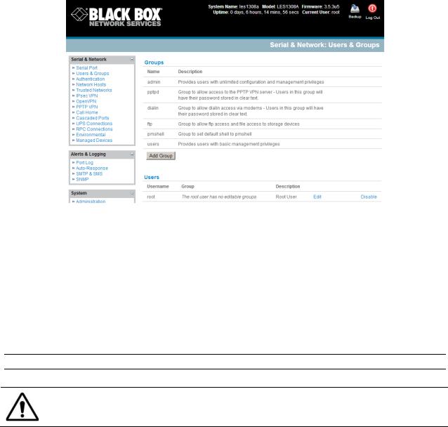
ports and serially connected devices, network connected hosts, and connected power devices; and to view associated logs and configure alerts.
A User can also use the Management Console, but has limited menu access to control select devices, review their logs and access them using the built-in java terminal or control power to them.
The console server runs an embedded Linux operating system, and experienced Linux® and UNIX® users may prefer to configure it at the command line. To get command line access, connect through a terminal emulator or communications program to the console serial port; connect via ssh or telnet through the LAN; or connect through an SSH tunneling to the console server.
Manual Conventions
This manual uses different fonts and typefaces to show specific actions:
Note Text presented like this indicates issues to note.
Text presented like this highlights important information. Make sure you read and follow these warnings.
Text presented with an arrow head indent indicates an action you should take as part of the procedure.
Bold text indicates text that you type, or the name of a screen object (for example, a menu or button) on the Management Console.
Italic text indicates a text command you enter at the command line level.
Publishing history
_____________________________________________________________________
724-746-5500 | blackbox.com |
Page 15 |
Date |
Revision |
Update details |
September 2011 |
1.1 |
Prerelease |
October 2011 |
2.0 |
Release for V2.8 firmware and later |
December 2012 |
3.0 |
Release for V3.5 firmware and later |
_____________________________________________________________________
724-746-5500 | blackbox.com |
Page 16 |
Copyright
©Black Box Corporation 2011. All Rights Reserved.
Information in this document is subject to change without notice and does not represent a commitment on the part of Black Box. Black Box provides this document “as is,” without warranty of any kind, either expressed or implied, including, but not limited to, the implied warranties of fitness or merchantability for a particular purpose.
Black Box may make improvements and/or changes in this manual or in the product(s) and/or the program(s) described in this manual at any time. This manual could include technical inaccuracies or typographical errors. Changes are periodically made to the information herein; these changes may be incorporated in new editions of the publication.
Notice to Users
Use proper back-up systems and necessary safety devices to protect against injury, death, or property damage caused by system failure. This protection is the user’s responsibility.
This device is not approved for use as a life-support or medical system.
Any changes or modifications made to this device without the explicit approval or consent of Black Box will void Black Box of any liability or responsibility of injury or loss caused by any malfunction.
This equipment is for indoor use and all the communication wirings are limited to the inside of the building.
_____________________________________________________________________
724-746-5500 | blackbox.com |
Page 17 |
Chapter 2 |
Installation |
Introduction
This chapter describes how to install the console server hardware and connect it to controlled devices.
To avoid physical and electrical hazards please read Appendix C on Safety.
2.1Models
There are multiple console server models, each with a different number of network and serial ports or power supply configurations:
|
Serial |
USB |
Network |
Console |
Modem |
RJ |
Power |
Memory |
|
Ports |
Ports |
Ports |
Port |
|
Pinout |
|
(flash/RAM) |
LES1508A |
8 |
2 |
2 |
1 |
- |
02 |
Ext AC/DC |
16/64MB, 4GB |
LES1448A |
48 |
2 |
2 |
1 |
Internal CDMA |
01 |
Dual AC |
16/64MB, 16GB |
LES1432A |
32 |
2 |
2 |
1 |
Internal CDMA |
01 |
Dual AC |
16/64MB, 16GB |
LES1416A |
16 |
2 |
2 |
1 |
Internal CDMA |
01 |
Dual AC |
16/64MB, 16GB |
LES1408A |
8 |
2 |
2 |
1 |
Internal CDMA |
01 |
Dual AC |
16/64MB, 16GB |
LES1348A |
48 |
2 |
2 |
1 |
Internal GSM |
01 |
Dual AC |
16/64MB, 16GB |
LES1332A |
32 |
2 |
2 |
1 |
Internal GSM |
01 |
Dual AC |
16/64MB, 16GB |
LES1316A |
16 |
2 |
2 |
1 |
Internal GSM |
01 |
Dual AC |
16/64MB, 16GB |
LES1308A |
8 |
2 |
2 |
1 |
Internal GSM |
01 |
Dual AC |
16/64MB, 16GB |
LES1248A-R2 |
48 |
3 |
2 |
1 |
Internal V.92 |
01 |
Dual AC |
16/64MB, 16GB |
LES1232A |
32 |
3 |
2 |
1 |
Internal V.92 |
01 |
Dual AC |
16/64MB, 16GB |
LES1216A-R2 |
16 |
3 |
2 |
1 |
Internal V.92 |
01 |
Dual AC |
16/64MB, 16GB |
LES1208A-R2 |
8 |
3 |
2 |
1 |
Internal V.92 |
01 |
Dual AC |
16/64MB, 16GB |
LES1148A |
48 |
- |
1 |
1 |
- |
00 |
Single AC |
16/64MB |
LES1132A |
32 |
- |
1 |
1 |
- |
00 |
Single AC |
16/64MB |
LES1116A |
16 |
- |
1 |
1 |
- |
00 |
Single AC |
16/64MB |
LES1108A |
8 |
- |
1 |
1 |
- |
00 |
Ext AC/DC |
8/16MB |
The next sections show the components shipped with each of these models.
Unpack your kit and verify you have all the parts shown above, and that they all appear in good working order.
_____________________________________________________________________
724-746-5500 | blackbox.com |
Page 18 |
If you are installing the console server in a rack, you will need to attach the rack mounting brackets supplied with the unit, then install the unit in the rack. Make sure you follow the Safety Precautions listed in Appendix C.
Connect your console server to the network, to the serial ports of the controlled devices, and to power as outlined next.
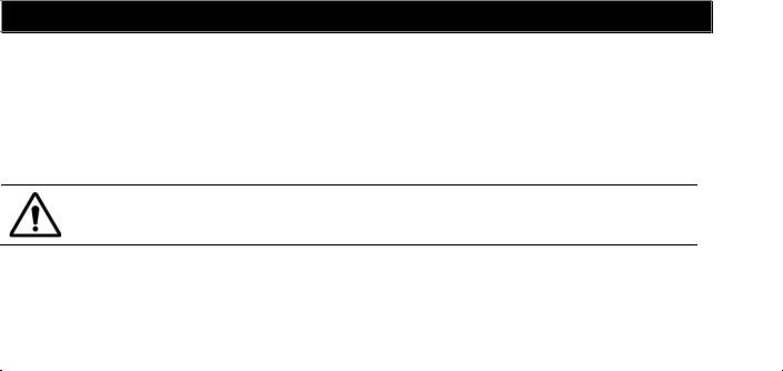
2.1.1Kit components LES1508A Console Server
LES1508A Console Server
(2) UTP CAT5 blue cables
DB9F-RJ45S straight and DB9F-RJ45S cross-over connectors
Power Supply 12VDC 1.0A Wall mount
Printed Quick Start Guide and this User‘s Manual on CD-ROM
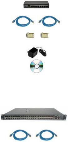
2.1.2Kit components LES1308ALES1348A and LES1408A - LES1448A Advanced Console Servers
LES1308A, LES1316A, LES1332A, LES1348A, LES1408A,
LES1416A, LES1432A or LES1448A Advanced Console Server
(2) UTP CAT5 blue cables
_____________________________________________________________________
724-746-5500 | blackbox.com |
Page 19 |
DB9F-RJ45S straight and DB9F-RJ45S cross-over connectors
USB micro-AB adapter cable
Antenna with 10 foot extension cable
Dual IEC AC power cords
Printed Quick Start Guide and User’s Manual on CD-ROM
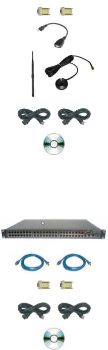
2.1.3 Kit components LES1208A-R2, LES1216A-R2, LES1232A and LES1248A-R2 Advanced Console Servers
LES1208A-R2, LES1216A-R2, LES1232A or LES1248A-R2
Advanced Console Server
(2) UTP CAT5 blue cables
DB9F-RJ45S straight and DB9F-RJ45S cross-over connectors
Dual IEC AC power cords
Printed Quick Start Guide and User’s Manual on CD-ROM
_____________________________________________________________________
724-746-5500 | blackbox.com |
Page 20 |
2.1.4Kit components LES1116A, LES1132A and LES1148A Console Servers
LES1116A, LES1132A or LES1148A Console Server
(2) UTP CAT5 blue cables
DB9F-RJ45S straight and DB9F-RJ45S cross-over connectors
IEC AC power cord
Printed Quick Start Guide and User’s Manual on CD-ROM
2.1.5Kit components LES1108A Console Server
LES1108A Console Server
(2) UTP CAT5 blue cables
DB9F-RJ45S straight and DB9F-RJ45S cross-over connectors
5-VDC, 2.0A, Power Supply with IEC Socket and AC power cable
Printed Quick Start Guide and this User‘s Manual on CD-ROM
2.2Power connection
2.2.1LES1508A power
The LES1508A includes an external DC power supply unit. This unit accepts an AC input voltage between 100 and 250 VAC with a frequency of 50Hz or 60Hz. The DC power supply comes with a selection of wall socket adapters for each geographic region (North American, Europe, UK, Japan or Australia). The 12-
_____________________________________________________________________
724-746-5500 | blackbox.com |
Page 21 |
VDC connector from the power supply plugs into the 12VDC (PWR) power socket on the side of the LES1508A.
2.2.2LES1408A - LES1448A, LES1308ALES1348A and LES1208A - LES1248A power
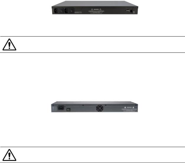
The Advanced Console Server models (LES1208A-R2, LES1216A-R2, LES1232A, LES1248A-R2, LES1308A, LES1316A, LES1332A, LES1348A, LES1408A, LES1416A, LES1432A and LES1448A) all have dual universal AC power supplies with auto failover built in. These power supplies each accept AC input voltage between 100 and 240 VAC with a frequency of 50 or 60 Hz. The total power consumption per console server is less than 30W. Two IEC AC power sockets are located at the rear of the metal case, and these IEC power inlets use conventional IEC AC power cords.
Power cords for various regions are available, although the North American power cord is provided by default. There is a warning notice printed on the back of each unit.
To avoid electrical shock, connect the power cord grounding conductor to ground!
2.2.2LES1116A, LES1132A and LES1148A power
The LES1116A, LES1132A and LES1148A models have a built-in universal auto-switching AC power supply. This power supply accepts AC input voltage between 100 and 240 VAC with a frequency of 50 or 60 Hz. The power consumption is less than 20W.
The LES1116A, LES1132A and LES1148A models have an IEC AC power socket located in the rear of the metal case. This IEC power inlet uses a conventional IEC AC power cord, and the power cords for various regions are available. Call Black Box Technical Support for details at 724-746-5500. (The North American power cord is provided by default.) There is a warning notice printed on the back of each unit.
To avoid electrical shock, connect the power cord grounding conductor to ground.
_____________________________________________________________________
724-746-5500 | blackbox.com |
Page 22 |
2.2.4LES1108A power
The LES1108A includes an external DC power supply unit. This unit accepts an AC input voltage between 100 and 250 VAC with a frequency of 50Hz or 60Hz. The DC power supply has an IEC AC power socket, which accepts a conventional IEC AC power cord. The power cord for North America is included in the kit. The 5-VDC connector from the power supply plugs into the 5VDC power socket on the rear of the LES1108A.
2.3Network connection
The RJ-45 LAN ports are located on the rear panel of the LES1108A and LES1508A, and on the front panel of the rack-mount console servers. Use industry standard Cat5 cabling and connectors. Make sure that you only connect the LAN port to an Ethernet network that supports 10BASE-T/100BASE-T. To initially configure the console server, you must connect a PC or workstation to the console server’s principal network port (labeled NETWORK1 or LAN).
2.4Serial Port connection
The RJ-45 serial ports are located on the rear panel of the LES1108A and on the front panel of the LES1508A and rackmount console servers.
The LES1508A Console Server has a Cisco RJ-45 pinout shown below:
|
|
|
|
PIN |
SIGNAL |
DEFINITION |
DIRECTION |
1 |
CTS |
Clear To Send |
Input |
2 |
DSR |
Data Set Ready |
Input |
3 |
RXD |
Receive Data |
Input |
4 |
GND |
Signal Ground |
NA |
5 |
GND |
Signal Ground |
NA |
6 |
TXD |
Transmit Data |
Output |
7 |
DTR |
Data Terminal Ready |
Output |
8 |
RTS |
Request To Send |
Output |
|
|
|
|
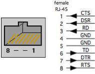
The LES1108A, LES1116A, LES1132A and LES1148A Console Servers have the Black Box Classic RJ-45 pinout shown below:
_____________________________________________________________________
724-746-5500 | blackbox.com |
Page 23 |
|
|
|
|
PIN |
SIGNAL |
DEFINITION |
DIRECTION |
1 |
RTS |
Request To Send |
Output |
2 |
DSR |
Data Set Ready |
Input |
3 |
DCD |
Data Carrier Detect |
Input |
4 |
RXD |
Receive Data |
Input |
5 |
TXD |
Transmit Data |
Output |
6 |
GND |
Signal Ground |
NA |
7 |
DTR |
Data Terminal Ready |
Output |
8 |
CTS |
Clear To Send |
Input |
|
|
|
|
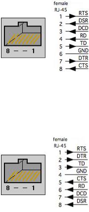
The LES1208A-R2, LES1216A-R2, LES1232A, LES1248A-R2, LES1308A, LES1316A, LES1332A, LES1348A, LES1408A, LES1416A, LES1432A and LES1448A Advanced Console Servers have the Cyclades RJ-45 pinout shown next:
|
|
|
|
PIN |
SIGNAL |
DEFINITION |
DIRECTION |
1 |
RTS |
Request To Send |
Output |
2 |
DTR |
Data Terminal Ready |
Output |
3 |
TXD |
Transmit Data |
Output |
4 |
GND |
Signal Ground |
NA |
5 |
CTS |
Clear To Send |
Input |
6 |
RXD |
Receive Data |
Input |
7 |
DCD |
Data Carrier Detect |
Input |
8 |
DSR |
Data Set Ready |
Input |
|
|
|
|
The rackmount console servers also have a DB9 LOCAL (Console/Modem) port on front panel. The LE1108A has a DB9 LOCAL (Console/Modem) port on rear panel. With the LES1508, Serial Port 1 is configured by default in Local Console (modem) mode.
Conventional CAT5 cabling with RJ-45 jacks is used for serial connections. Before connecting an external device’s console port to the console server serial port, confirm that the device supports the standard RS-232C (EIA-232).
Black Box supplies a range of cables and adapters that may be required to connect to the more popular servers and network appliances. Call Technical Support at 724-746-5500 for details.
2.5USB Port Connection
The LES1208A-R2, LES1216A-R2, LES1232A and LES1248A-R2 console servers each also have one USB1.1 port on the front face and two additional USB 2.0 ports at the rear face (adjacent to modem jack).
The LES1308A, LES1316A, LES1332A, LES1348A, LES1408A, LES1416A, LES1432A and LES1448A console servers each also have one USB1.1 port on the front face and one additional USB 2.0 ports at the rear face. This USB2.0 port is adjacent to antenna connector and conne cts using the micro-AB USB cable.
The LES1508A console server has twoUSB 2.0 ports on the front face. The USB2.0 ports can be used for:
_____________________________________________________________________
724-746-5500 | blackbox.com |
Page 24 |
−connecting to USB consoles of Managed Devices (e.g. for managing UPS supplies)
−attaching other external USB peripherals (e.g. an external USB memory stick or modem)
−adding supported Sierra Wireless cellular USB modems
−plugging in USB hubs to provide additional ports
The USB1.1 port is best reserved for use with an external USB memory stick dedicated to recovery firmware boot images/ extended log file storage etc.
2.6Antenna and SIM
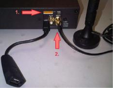
The LES1408A, LES1416A, LES1432A and LES1448A console servers also have an internal CDMA cellular modem requiring external antenna connection.
The LES1308A, LES1316A, LES1332A and LES1348A console servers have an internal GSM cellular modem that requires a SIM card and an external antenna.
Before powering on the console server:
Screw the external antenna coax cable onto the MAIN screw mount SMA connector on the rear of the console server (2).
The AUX connector can be used either for receive diversity or for GPS.
Your GSM cellular carrier will provide you with a SIM card. Insert the SIM card (1.) and it will lock into place. Take care to insert SIM card with contacts facing downwards.
_____________________________________________________________________
724-746-5500 | blackbox.com |
Page 25 |

Chapter 3 |
Initial System Configuration |
Introduction
This chapter provides step-by-step instructions for the console server’s initial configuration, and for connecting it to the Management or Operational LAN. The Administrator must:
Activate the Management Console.
Change the Administrator password.
Set the IP address console server’s principal LAN port.
Select the network services that will be supported.
This chapter also discusses the communications software tools that the Administrator may use to access the console server.
3.1Management console connection
Your console server is configured with a default IP Address 192.168.0.1 Subnet Mask 255.255.255.0 Directly connect a PC or workstation to the console server.
Note For initial configuration we recommend that you connect the console server directly to a single PC or workstation. However, if you choose to connect your LAN before completing the initial setup steps, it is important that:
you make sure that there are no other devices on the LAN with an address of 192.168.0.1
the console server and the PC/workstation are on the same LAN segment, with no interposed router appliances.
3.1.1 Connected PC/workstation set up
To configure the console server with a browser, the connected PC/workstation should have an IP address in the same range as the console server (e.g. 192.168.0.100):
To configure the IP Address of your Linux or Unix PC/workstation simply run ifconfig
For Windows PCs (Win9x/Me/2000/XP/ Vista/ 7/NT):
Click Start -> (Settings ->) Control Panel and double click Network Connections (for 95/98/Me, double click Network).
Right click on Local Area Connection and select Properties.
Select Internet Protocol (TCP/IP) and click Properties.
Select Use the following IP address and enter the following details:
o IP address: 192.168.0.100
_____________________________________________________________________
724-746-5500 | blackbox.com |
Page 26 |
oSubnet mask: 255.255.255.0
If you want to retain your existing IP settings for this network connection, click Advanced and Add the above as a secondary IP connection.
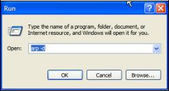
If it is not convenient to change your PC/workstation network address, you can use the ARP-Ping command to reset the console server IP address. To do this from a Windows PC:
Click Start -> Run (or select All Programs then Accessories then Run).
Type cmd and click OK to bring up the command line.
Type arp –d to flush the ARP cache.
Type arp –a to view the current ARP cache (this should be empty).
Now add a static entry to the ARP table and ping the console server to assign the IP address to the console server. In the example below, a console server has a MAC Address 00:13:C6:00:02:0F (designated on the label on the bottom of the unit) and we are setting its IP address to 192.168.100.23. Also the PC/workstation issuing the arp command must be on the same network segment as the console server (that is, have an IP address of 192.168.100.xxx)
Type arp -s 192.168.100.23 00-13-C6-00-02-0F (Note for UNIX the syntax is: arp -s 192.168.100.23 00:13:C6:00:02:0F).
Type ping -t 192.18.100.23 to start a continuous ping to the new IP Address.
Turn on the console server and wait for it to configure itself with the new IP address. It will start replying to the ping at this point.
Type arp –d to flush the ARP cache again.
3.1.2Browser connection
Activate your preferred browser on the connected PC/workstation and enter https://192.168.0.1 The Management Console supports all current versions of the popular browsers (Internet Explorer, Mozilla Firefox, Chrome, and more).
_____________________________________________________________________
724-746-5500 | blackbox.com |
Page 27 |
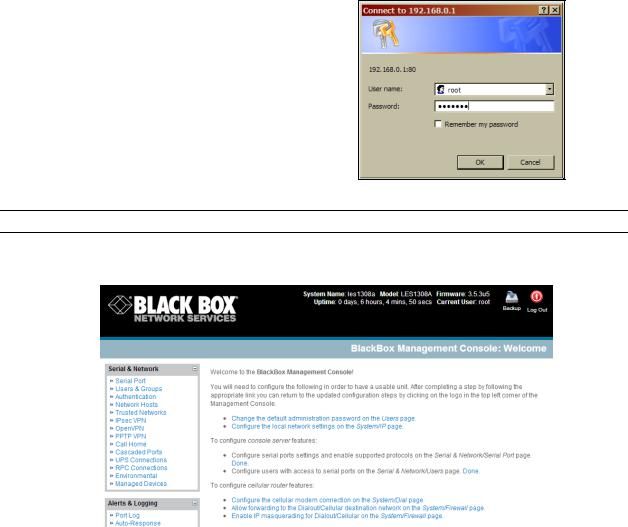
You will be prompted to log in. Enter the default administration username and administration password:
Username: root
Password: default
Note Console servers are factory configured with HTTPS access enabled and HTTP access disabled.
A Welcome screen, which lists initial installation configuration steps, will be displayed:
-Change the default administration password on the Users page (Chapter 3).
-Configure the local network settings on the System/IP page (Chapter 3).
-Configure port settings and enable ….. the Serial & Network/Serial Port page (Chapter 4).
-Configure users with access to serial ports on the Serial & Network/Users page (Chapter 4).
If your system has a cellular modem you will also be given the steps to configure the cellular router features:
-Configure the cellular modem connection on System/Dial page (Chapter 5)
-Allow forwarding to the cellular destination network on System/Firewall page (Chapter 5)
-Enable IP masquerading for cellular connection on System/Firewall page (Chapter 5)
_____________________________________________________________________
724-746-5500 | blackbox.com |
Page 28 |

After completing each of the above steps, you can return to the configuration list by clicking in the top left corner of the screen on the Black Box logo.
Note If you are not able to connect to the Management Console at 192.168.0.1 or if the default Username/Password were not accepted, then reset your console server (refer to Chapter 11).
3.2Administrator Password
For security reasons, only the administrator user named root can initially log into your console server. Only people who know the root password can access and reconfigure the console server itself. However, anyone who correctly guesses the root password could gain access (and the default root password is default). To avoid this, enter and confirm a new root password before giving the console server any access to, or control of, your computers and network appliances.
The system password can be changed by editing the root user on the Serial & Network: Users & Groups form
Select Change default administration password on the Welcome screen which will take you to
Serial & Network: Users & Groups where you can add a new confirmed Password for the user root
Enter a new Password then re-enter it in Confirm . This is the new password for root, the main administrative user account, so choose a complex password, and keep it safe.
Note There are no restrictions on the characters that can be used in the Password. It can contain up to 254 characters. However, only the first eight System Password characters are used to make the password hash.
_____________________________________________________________________
724-746-5500 | blackbox.com |
Page 29 |
Click Apply. Since you have changed the password you will be prompted to log in again. This time, use the new password.
Note If you are not confident that your console server has the current firmware release, you can upgrade. Refer to Upgrade Firmware—Chapter 10.
3.2.1Set up new administrator
It is also recommended that you set up a new Administrator user as soon as convenient and log-in as this new user for all ongoing administration functions (rather than root).
This Administrator can be configured in the admin group with full access privileges through the Serial & Network: Users & Groups menu (refer Chapter 4 for details)
3.2.2Name the console server
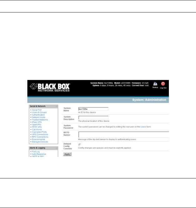
It is also recommended that you set up a System Name for your console server to make it simple to identify.
Select System: Administration and enter a System Name and System Description for the console server to give it a unique ID.
Note The System Name can contain from 1 to 64 alphanumeric characters (however you can also use the special characters “-”, “_”, and “.”)
There are no restrictions on the characters that can be used in the System Description or the System Password (each can contain up to 254 characters). However, only the first eight System Password characters are used to make the password hash.
The MOTD Banner can be used to display a “message of the day” text to users
Click Apply
3.3Network IP address
_____________________________________________________________________
724-746-5500 | blackbox.com |
Page 30 |
Loading...