


Black Box SW723A-R4, SW721A-R4, KV3108SA-R4, SW724A-R4, SW722A-R4 User Manual
...
JUNE 2000
|
13 |
14 |
15 |
16 |
|
|
|||
|
9 |
10 |
11 |
12 |
|
|
|||
|
5 |
6 |
7 |
8 |
|
|
|||
Power |
1 |
2 |
3 |
4 |
|
SW721A-R4
SW722A-R4
KV3108SA-R4
SW723A-R4
SW724A-R4
SW725A-R4
Customer Support Information:
FREE tech support 24 hours a day, 7 days a week: Call 724-746-5500 or fax 724-746-0746. Mailing address: Black Box Corporation, 1000 Park Dr., Lawrence, PA 15055-1018 World-Wide Web: www.blackbox.com • E-mail: info@blackbox.com
© Copyright 2000. Black Box Corporation. All rights reserved.
JUNE 2000
SW721A-R4 SW722A-R4
KV3108SA-R4 SW723A-R4
SW724A-R4 SW725A-R4
Step-By-Step Quick Install Guide for the ServSwitch™
|
13 |
14 |
15 |
16 |
|
|
|||
|
9 |
10 |
11 |
12 |
|
|
|||
|
5 |
6 |
7 |
8 |
|
|
|||
Power |
1 |
2 |
3 |
4 |
|
1. Introduction
This guide is designed to quickly show you how to attach cables and equipment in order to install a ServSwitch system. For just the basics, look over the diagrams on the next four pages. More detailed instructions begin on page 4.
SERVSWITCH™ QUICK INSTALL GUIDE
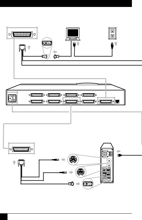
1 |
Attach User Adapter Cable. |
2 |
Attach monitor |
3 |
Plug in monitor. |
|
(VGA type shown). |
|
MONITOR/KEYBOARD/MOUSE
POWER |
CPU 7 |
CPU 8 |
CPU 5 |
CPU 6 |
|
|
|
|
|
|
|
|
|
|
CPU 3 |
CPU 4 |
CPU 1 |
CPU 2 |
MONITOR/KEYBOARD/MOUSE |
RS-232 |
ServSwitch
5 Use CPU Adapter Cable to attach CPU this way (PS/2 CPU shown):
CPU 1
Unlabeled
Labeled "MOUSE" |
2
SERVSWITCH™ QUICK INSTALL GUIDE
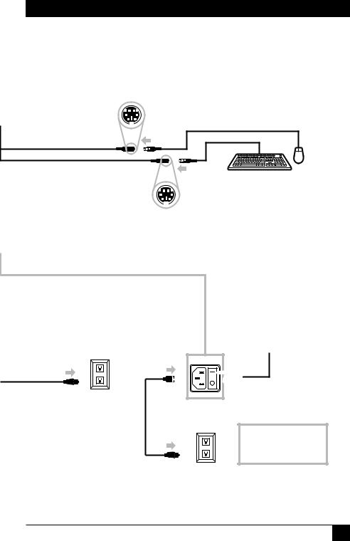
4 Attach your keyboard and mouse this way (PS/2 equipment shown):
Labeled "MOUSE" |
Unlabeled |
6 |
Plug in CPU. |
7 |
Plug in |
8 |
Turn on |
|
ServSwitch. |
ServSwitch. |
|||
|
|
|
|
POWER |
|
|
|
|
|
|
|
9 Turn on monitor and all CPUs.
3
SERVSWITCH™ QUICK INSTALL GUIDE
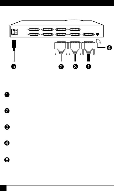
The rest of this guide is divided into five sections, one for each connection type:
POWER |
CPU 7 |
CPU 8 |
CPU 5 |
CPU 6 |
|
|
|
CPU 3 |
CPU 4 |
CPU 1 |
CPU 2 |
MONITOR/KEYBOARD/MOUSE |
RS-232 |
RS-232
Power |
Cascade |
CPU |
User |
Figure 1. Connection sequence.
Required: Section 2, User-Station Connections (see page 5).
Optional: Section 3, Cascade Connections (see page 10).
Required: Section 4, CPU Connections (see page 11).
Optional: Section 5, The RS-232 Connection (see page 18).
Required: Section 6, The Power Connection (see page 20).
4

SERVSWITCH™ QUICK INSTALL GUIDE
2. User-Station Connections
Which cables you use for these and how you connect them to the ServSwitch and to your user-station equipment will depend on what type of equipment you’re using:
If your keyboard |
And if your |
Refer to this section |
and mouse are |
monitor is this |
(on this page): |
this type (with this |
type (with this |
|
connector): |
connector): |
|
IBM® PS/2® , RS/6000® , |
VGA/multisync |
Section 2.1 (page 6) |
or SGI® (6-pin mini-DIN) |
(HD15) |
|
IBM PC/AT® keyboard, |
VGA/multisync |
Section 2.2 (page 7) |
(5-pin DIN), RS-232 |
(HD15) |
|
serial mouse (DB9) |
|
|
IBM PS/2 or RS/6000 |
RS/6000 (13W3) |
Section 2.3 (page 8) |
(6-pin mini-DIN) |
|
|
IBM PS/2 or SGI |
SGI (13W3) |
Section 2.4 (page 9) |
(6-pin mini-DIN) |
|
|
5
SERVSWITCH™ QUICK INSTALL GUIDE
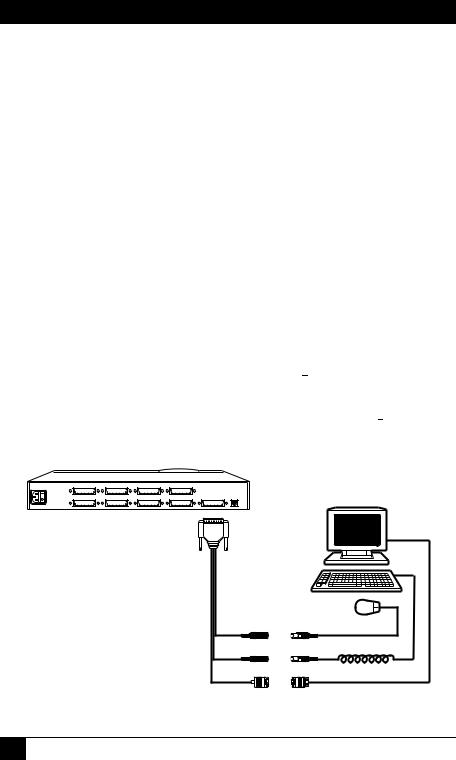
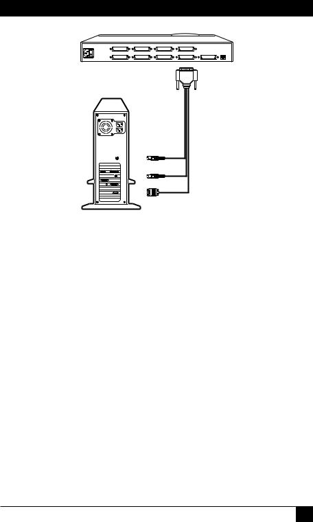
2.1 IBM PS/2 COMPATIBLE KEYBOARD AND MOUSE, VGA/MULTISYNC MONITOR
If your keyboard and mouse are IBM PS/2 compatible (which includes current RS/6000 and SGIkeyboards and mice, as well as the Microsoft® IntelliMouse®), and your monitor is a VGA, SVGA, XGA, or multisync type with an HD15 video connector, first choose your Monitor/Keyboard/Mouse Adapter Cable (User Cable):
•If your video resolution is not higher than 1024 x 768 pixels, and if your equipment is within 20 ft. (6.1 m) of the Switch, you can use the standard (non-coaxial) cable with the product code EHN054.
•If your video resolution is higher than 1024 x 768, or if your equipment is farther than 20 ft. (6.1 m) from the Switch, you should use the coaxial cable with the product code EHN283.
When you have the correct cable, hook it up to the ServSwitch and your equipment this way, as shown in Figure 2:
•Plug the cable’s DB25  connector into the Switch’s MONITOR/ KEYBOARD/MOUSE port.
•Plug the mouse into the cable’s 6-pin mini-DIN  connector with the
“MOUSE” label on it.
•Plug the keyboard into the cable’s unlabeled 6-pin mini-DIN  connector.
•Plug the monitor into the cable’s HD15  connector.
POWER |
CPU 7 |
CPU 8 |
CPU 5 |
CPU 6 |
|
|
|
CPU 3 |
CPU 4 |
CPU 1 |
CPU 2 |
MONITOR/KEYBOARD/MOUSE |
RS-232 |
EHN054 or
EHN283
Figure 2. PS/2 type user-station connections.
6
SERVSWITCH™ QUICK INSTALL GUIDE
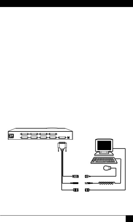
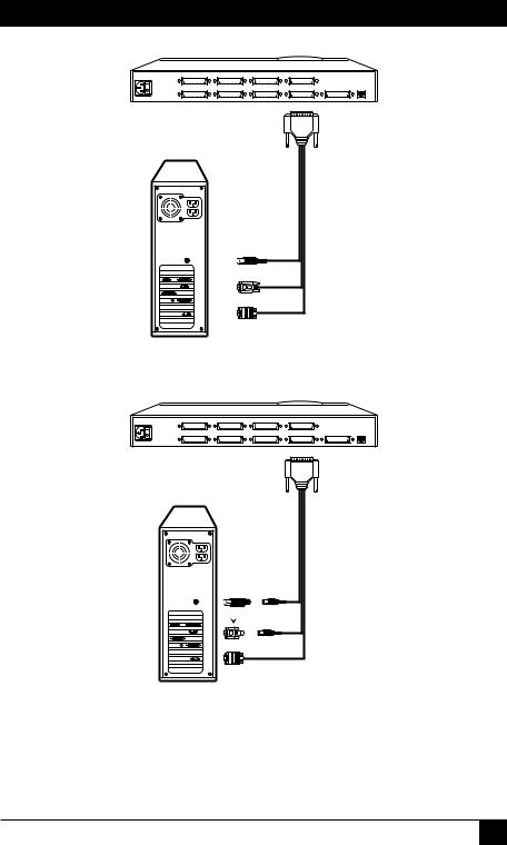
2.2 IBM PC/AT COMPATIBLE KEYBOARD, RS-232 SERIAL MOUSE, VGA/MULTISYNC MONITOR
If your keyboard is PC/AT compatible, your mouse is an RS-232 serial type, and your monitor is a VGA, SVGA, XGA, or multisync type with an HD15 video connector, first choose your Monitor/Keyboard/Mouse Adapter Cable (User Cable):
•If your video resolution is not higher than 1024 x 768 pixels, and if your equipment is within 20 ft. (6.1 m) of the Switch, you can use the standard (non-coaxial) cable with the product code EHN052.
•If your video resolution is higher than 1024 x 768, or if your equipment is farther than 20 ft. (6.1 m) from the Switch, you should use the coaxial cable with the product code EHN270.
When you have the correct cable, hook it up to the ServSwitch and your equipment this way, as shown in Figure 3:
•Plug the cable’s DB25  connector into the Switch’s MONITOR/ KEYBOARD/MOUSE port.
•Plug the mouse into the cable’s DB9  connector.
•Plug the keyboard into the cable’s 5-pin DIN  connector.
•Plug the monitor into the cable’s HD15  connector.
POWER |
CPU 7 |
CPU 8 |
CPU 5 |
CPU 6 |
|
|
|
CPU 3 |
CPU 4 |
CPU 1 |
CPU 2 |
MONITOR/KEYBOARD/MOUSE |
RS-232 |
EHN052 or
EHN270
Figure 3. PC/AT type user-station connections.
7
SERVSWITCH™ QUICK INSTALL GUIDE
2.3 IBM PS/2 COMPATIBLE KEYBOARD AND MOUSE, RS/6000 MONITOR
If your keyboard and mouse are IBM PS/2 compatible (which includes current RS/6000 keyboards and mice, as well as the Microsoft IntelliMouse), and your monitor is an RS/6000 type with a 13W3 video connector, use the coaxial Monitor/Keyboard/Mouse Adapter Cable (User Cable) with the product code EHN521-0001. (Note that this cable is available as a stock item only in a 1-ft. [0.3-m] length; call for a quote if you need a longer version.) Hook this cable up to the ServSwitch and your equipment this way, as shown in Figure 4:
•Plug the cable’s DB25  connector into the Switch’s MONITOR/ KEYBOARD/MOUSE port.
•Plug the mouse into the cable’s 6-pin mini-DIN  connector with the
“MOUSE” label on it.
•Plug the keyboard into the cable’s unlabeled 6-pin mini-DIN  connector.
•Plug the monitor into the cable’s 13W3  connector.
POWER |
CPU 7 |
CPU 8 |
CPU 5 |
CPU 6 |
|
|
|
CPU 3 |
CPU 4 |
CPU 1 |
CPU 2 |
MONITOR/KEYBOARD/MOUSE |
RS-232 |
EHN521-0001
Figure 4. RS/6000 type user-station connections.
8
SERVSWITCH™ QUICK INSTALL GUIDE
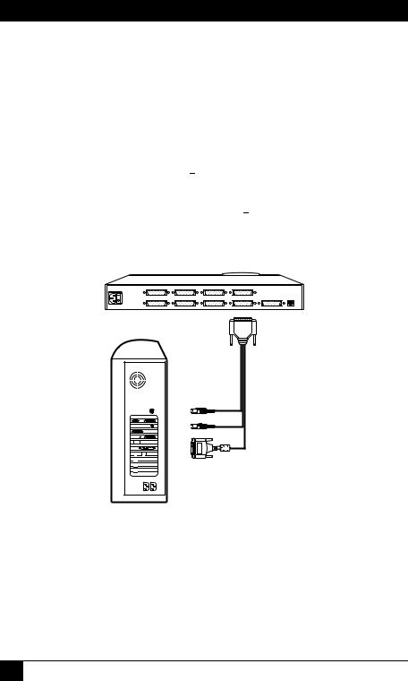
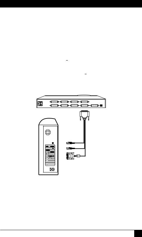
2.4 IBM PS/2 COMPATIBLE KEYBOARD AND MOUSE, SGI MONITOR
If your keyboard and mouse are IBM PS/2 compatible (which includes current SGI keyboards and mice, as well as the Microsoft IntelliMouse), and your monitor is an SGI type with a 13W3 video connector, use the coaxial Monitor/ Keyboard/Mouse Adapter Cable (User Cable) with the product code EHN501-0001. (Note that this cable is available as a stock item only in a 1-ft. [0.3-m] length; call for a quote if you need a longer version.) Hook this cable up to the ServSwitch and your equipment this way, as shown in Figure 5:
•Plug the cable’s DB25  connector into the Switch’s MONITOR/ KEYBOARD/MOUSE port.
•Plug the mouse into the cable’s 6-pin mini-DIN  connector with the
“MOUSE” label on it.
•Plug the keyboard into the cable’s unlabeled 6-pin mini-DIN  connector.
•Plug the monitor into the cable’s 13W3  connector.
POWER |
CPU 7 |
CPU 8 |
CPU 5 |
CPU 6 |
|
|
|
CPU 3 |
CPU 4 |
CPU 1 |
CPU 2 |
MONITOR/KEYBOARD/MOUSE |
RS-232 |
EHN501-0001
Figure 5. SGI type user-station connections.
9
SERVSWITCH™ QUICK INSTALL GUIDE
3. Cascade Connections (Optional)
If you want to connect submaster (slave) ServSwitch units to your master unit, use the coaxial Expansion Cable EHN284. Plug one end of this cable (it doesn’t matter which end) into the submaster unit’s MONITOR/KEYBOARD/ MOUSE port. If this is the first submaster, plug the other end of the cable into the master Switch’s CPU 1 port. If this is the second submaster, plug the other end into the master Switch’s CPU 2 port, and so on. See Figure 6. (For more information about cascading, refer to Section 3.3 of your ServSwitch manual.)
Master Unit
POWER |
CPU 7 |
CPU 8 |
CPU 5 |
CPU 6 |
|
CPU 3 |
CPU 4 |
CPU 1 |
CPU 2 |
MONITOR/KEYBOARD/MOUSE RS-232 |
|
|
|
|
|
EHN284 |
|
Submaster Unit |
|
|
||
POWER |
CPU 7 |
CPU 8 |
CPU 5 |
CPU 6 |
|
|
CPU 3 |
CPU 4 |
CPU 1 |
CPU 2 |
MONITOR/KEYBOARD/MOUSE RS-232 |
Figure 6. A cascade connection.
10

SERVSWITCH™ QUICK INSTALL GUIDE
4. CPU Connections
Which cables you use and how you connect them will depend on what type of equipment you’re using:
If your CPU’s keyboard |
And if your CPU’s |
Refer to this section |
and mouse ports are |
video port is this |
(on this page): |
this type (with this |
type (with this |
|
connector): |
connector): |
|
IBM PS/2 type |
VGA etc. (HD15) |
Section 4.1 (page 12) |
(6-pin mini-DIN) |
|
|
IBM PC/AT keyboard |
VGA etc. (HD15) |
Section 4.2 (page 14) |
(5-pin DIN), RS-232 |
|
|
serial mouse (DB9) |
|
|
IBM RS/6000 (PS/2 type, |
RS/6000 (13W3) |
Section 4.3 (page 16) |
6-pin mini-DIN) |
|
|
SGI (PS/2 type, |
SGI (13W3) |
Section 4.4 (page 17) |
6-pin mini-DIN) |
|
|
11

SERVSWITCH™ QUICK INSTALL GUIDE
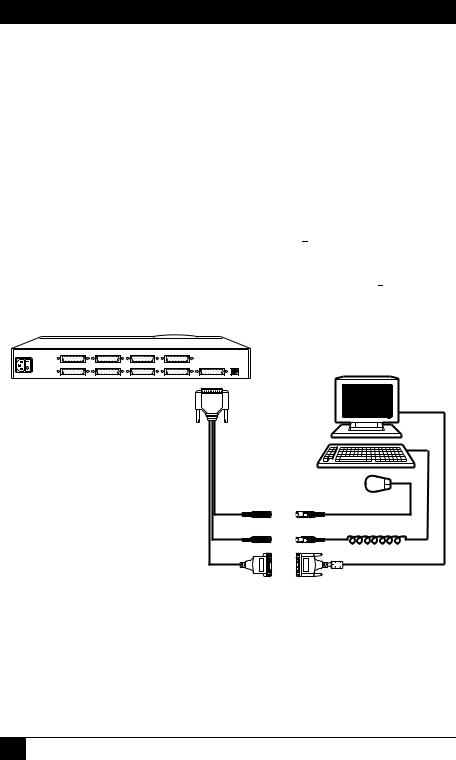
4.1 IBM PS/2 COMPATIBLE KEYBOARD AND MOUSE PORTS, VGA TYPE VIDEO PORTS
If a CPU’s keyboard and mouse ports are IBM PS/2 compatible (which includes current RS/6000 and SGI CPUs), and its video port is a VGA, SVGA, XGA, or a compatible type with an HD15 connector, first choose your CPU Adapter Cable:
•If your video resolution is not higher than 1024 x 768 pixels, and if the CPU is within 20 ft. (6.1 m) of the Switch, you can use the standard (noncoaxial) cable with the product code EHN051.
•If your video resolution is higher than 1024 x 768, or if the CPU is farther than 20 ft. (6.1 m) from the Switch, you should use the coaxial cable with the product code EHN282. (This cable will come with keyboard and mouse adapters that you will not use.)
When you have the correct cable, hook it up to the ServSwitch and the CPU this way, as shown in Figure 7 on the next page:
•Plug the cable’s DB25  connector into one of the Switch’s numbered CPU ports.
•Plug the cable’s 6-pin mini-DIN  connector with the “MOUSE” label on it into the CPU’s mouse port.
•Plug the cable’s unlabeled 6-pin mini-DIN  connector into the CPU’s keyboard port.
•Plug the cable’s HD15  connector into the CPU’s video port.
12
SERVSWITCH™ QUICK INSTALL GUIDE
POWER |
CPU 7 |
CPU 8 |
CPU 5 |
CPU 6 |
|
|
|
CPU 3 |
CPU 4 |
CPU 1 |
CPU 2 |
MONITOR/KEYBOARD/MOUSE |
RS-232 |
EHN051 or
EHN282
To kbd port
To mouse port
To video port
Figure 7. PS/2 type CPU connections.
13

SERVSWITCH™ QUICK INSTALL GUIDE
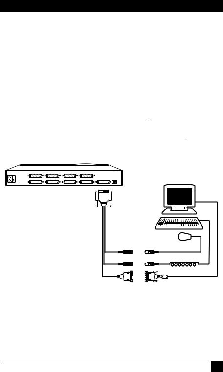
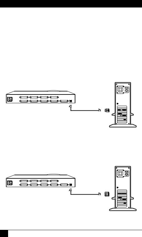
4.2 IBM PC/AT COMPATIBLE KEYBOARD PORT, RS-232 SERIAL MOUSE PORT, VGA TYPE
VIDEO PORT
If a CPU’s keyboard port is PC/AT compatible, its mouse port is an RS-232 serial type, and its video port is a VGA, SVGA, XGA, or compatible type with an HD15 connector, first choose your CPU Adapter Cable:
•If your video resolution is not higher than 1024 x 768 pixels, and if the CPU is within 20 ft. (6.1 m) of the Switch, you can use the standard (noncoaxial) cable with the product code EHN048.
•If your video resolution is higher than 1024 x 768, or if the CPU is farther than 20 ft. (6.1 m) from the Switch, you should use the coaxial cable with the product code EHN282, including the adapters that come with it.
If you use the EHN048, hook it up to the ServSwitch and the CPU this way, as shown in Figure 8 on the next page:
•Plug the cable’s DB25  connector into one of the Switch’s numbered CPU ports.
•Plug the cable’s DB9  connector into the CPU’s mouse port.
•Plug the cable’s 5-pin DIN  connector into the CPU’s keyboard port.
•Plug the cable’s HD15  connector into the CPU’s video port.
If you use the EHN282, hook it up to the ServSwitch and the CPU this way, as shown in Figure 9 on the next page:
•Plug the cable’s DB25  connector into one of the Switch’s numbered CPU ports.
•Plug the cable’s 6-pin mini-DIN  connector with the “MOUSE” label on it into the 6-pin mini-DIN end of the included mouse adapter. Then plug
the DB9 end of the adapter into the CPU’s mouse port.
•Plug the cable’s unlabeled 6-pin mini-DIN  connector into the 6-pin mini-DIN end of the included keyboard adapter. Then plug the 5-pin DIN
end of the adapter into the CPU’s keyboard port.
•Plug the cable’s HD15  connector into the CPU’s video port.
14
SERVSWITCH™ QUICK INSTALL GUIDE
POWER |
CPU 7 |
CPU 8 |
CPU 5 |
CPU 6 |
|
|
|
CPU 3 |
CPU 4 |
CPU 1 |
CPU 2 |
MONITOR/KEYBOARD/MOUSE |
RS-232 |
EHN048
To kbd port
To mouse port
To video port
Figure 8. PC/AT type CPU connections (standard cable).
POWER |
CPU 7 |
CPU 8 |
CPU 5 |
CPU 6 |
|
|
|
CPU 3 |
CPU 4 |
CPU 1 |
CPU 2 |
MONITOR/KEYBOARD/MOUSE |
RS-232 |
EHN282
To kbd port
 Adapters
To mouse port
To video port
Figure 9. PC/AT type CPU connections (coaxial cable).
15
SERVSWITCH™ QUICK INSTALL GUIDE
4.3 IBM PS/2 COMPATIBLE KEYBOARD AND MOUSE PORTS, RS/6000 VIDEO PORT
If a CPU’s keyboard and mouse ports are IBM PS/2 compatible (which includes current RS/6000 CPUs), and its video port is an RS/6000 type with a 13W3 connector, use the coaxial CPU Adapter Cable EHN520. Hook this cable up to the ServSwitch and the CPU this way, as shown in Figure 10:
•Plug the cable’s DB25  connector into one of the Switch’s numbered CPU ports.
•Plug the cable’s 6-pin mini-DIN  connector with the “MOUSE” label on it into the CPU’s mouse port.
•Plug the cable’s unlabeled 6-pin mini-DIN  connector into the CPU’s keyboard port.
•Plug the cable’s 13W3  connector into the CPU’s video port.
POWER |
CPU 7 |
CPU 8 |
CPU 5 |
CPU 6 |
|
|
|
CPU 3 |
CPU 4 |
CPU 1 |
CPU 2 |
MONITOR/KEYBOARD/MOUSE |
RS-232 |
EHN520
To kbd port
To mouse port
To video port
Figure 10. RS/6000 type CPU connections.
16
SERVSWITCH™ QUICK INSTALL GUIDE
4.4 IBM PS/2 COMPATIBLE KEYBOARD AND MOUSE PORTS, SGI VIDEO PORT
If a CPU’s keyboard and mouse ports are IBM PS/2 compatible (which includes current SGI CPUs), and its video port is an SGI type with a 13W3 connector, use the coaxial CPU Adapter Cable EHN500. Hook this cable up to the ServSwitch and your equipment this way, as shown in Figure 11:
•Plug the cable’s DB25  connector into one of the Switch’s numbered CPU ports.
•Plug the cable’s 6-pin mini-DIN  connector with the “MOUSE” label on it into the CPU’s mouse port.
•Plug the cable’s unlabeled 6-pin mini-DIN  connector into the CPU’s keyboard port.
•Plug the cable’s 13W3  connector into the CPU’s video port.
POWER |
CPU 7 |
CPU 8 |
CPU 5 |
CPU 6 |
|
|
|
CPU 3 |
CPU 4 |
CPU 1 |
CPU 2 |
MONITOR/KEYBOARD/MOUSE |
RS-232 |
EHN500
To kbd port
To mouse port
To video port
Figure 11. SGI type CPU connections.
17
SERVSWITCH™ QUICK INSTALL GUIDE
5. The RS-232 Connection (Required for Upgrading Firmware, Optional Otherwise)
To attach the ServSwitch’s RS-232 port to the RS-232 serial port of a PC or modem for upgrading firmware (required) or for out-of-band port switching and diagnostics (optional), you will need a 4- or 6-wire flat-satin modular cable and a modular adapter:
•If you are connecting the Switch directly to a DB9 male  computer serial port, use the 4-wire cable and the DB9 female adapter that came with the Switch, as shown in Figure 12. (If you lose the cable, you can replace it with our product code EL04MS. If you lose the adapter, you can replace it with our product code FA043.)
POWER |
CPU 7 |
CPU 8 |
CPU 5 |
CPU 6 |
|
Included |
|
CPU 3 |
CPU 4 |
CPU 1 |
CPU 2 |
MONITOR/KEYBOARD/MOUSE RS-232 |
adapter |
|
|
|
|
|
|
or FA043
Included 4-wire cable or EL04MS
Figure 12. RS-232 connection to DB9 male computer port.
•If you are connecting the Switch directly to a DB25 male  computer serial port, use the 4-wire cable that came with the Switch and the DB25 female adapter FA044, as shown in Figure 13. (If you lose the cable, you can replace it with our product code EL04MS.)
POWER |
CPU 7 |
CPU 8 |
CPU 5 |
CPU 6 |
|
Modular |
|
|
|
|
|
adapter |
|
|
CPU 3 |
CPU 4 |
CPU 1 |
CPU 2 |
MONITOR/KEYBOARD/MOUSE RS-232 |
FA044
Included 4-wire cable or EL04MS
Figure 13. RS-232 connection to DB25 male computer port.
18
SERVSWITCH™ QUICK INSTALL GUIDE
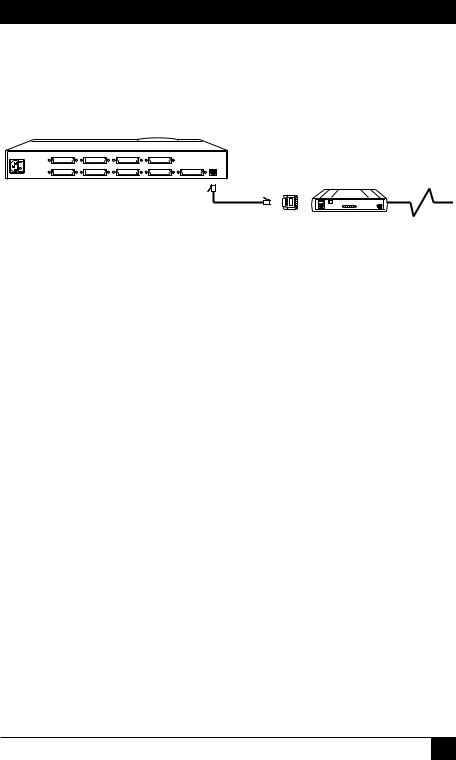
•If you are connecting the Switch to a computer at another site through a modem with a DB25 female  serial port, use the 6-wire cable EL06MS and the DB25 male adapter FA042, as shown in Figure 14.
POWER |
CPU 7 |
CPU 8 |
CPU 5 |
CPU 6 |
Modular |
|
|
CPU 3 |
CPU 4 |
CPU 1 |
CPU 2 MONITOR/KEYBOARD/MOUSE RS-232 |
adapter |
To phone |
|
|
|
|
|
network |
|
|
|
|
|
|
FA042 |
|
|
|
|
|
|
|
|
|
|
|
|
6-wire cable |
|
Modem |
|
|
|
|
EL06MS |
|
|
|
|
|
|
|
|
Figure 14. RS-232 connection to DB25 male computer port.
19
SERVSWITCH™ QUICK INSTALL GUIDE
6. The Power Connection
Attach the outlet end of the included power cord into the Switch. Attach the plug end of the cord to a wall outlet. See Figure15.
POWER |
CPU 7 |
CPU 8 |
CPU 5 |
CPU 6 |
|
|
|
CPU 3 |
CPU 4 |
CPU 1 |
CPU 2 |
MONITOR/KEYBOARD/MOUSE |
RS-232 |
Included power cord
Figure 15. The power connection.
20

NOTES
21

© Copyright 2000. Black Box Corporation. All rights reserved.
BLACK BOX and the  logo are registered trademarks, and ServSwitch is a trademark, of Black Box Corporation. IBM, PC/AT, PS/2, and RS/6000 are registered trademarks of International Business Machines Corporation.
Microsoft and IntelliMouse are trademarks or registered trademarks of Microsoft Corporation in the United States and/or other countries.
SGI is a registered trademark of SGI.
Any other trademarks mentioned in this document are acknowledged to be the property of the trademark owners.
CUSTOMER Order toll-free in the U.S. 24 hours, 7 A.M. Monday to midnight Friday: 877-877-BBOX SUPPORT FREE technical support, 24 hours a day, 7 days a week: Call 724-746-5500 or fax 724-746-0746
INFORMATION Mail order: Black Box Corporation, 1000 Park Drive, Lawrence, PA 15055-1018 Web site: www.blackbox.com • E-mail: info@blackbox.com

THE SERVSWITCH™ FAMILY
Welcome to the ServSwitchTM Family!
Thank you for purchasing a BLACK BOX® ServSwitch™ Brand KVM switch! We appreciate your business, and we think you’ll appreciate the many ways that your new ServSwitch keyboard/video/mouse switch will save you money, time, and effort.
That’s because our ServSwitch family is all about breaking away from the traditional, expensive model of computer management. You know, the one-size- fits-all-even-if-it-doesn’t model that says, “One computer gets one user station, no more, no less.” Why not a single user station (monitor, keyboard, and mouse) for multiple computers—even computers of different platforms? Why not a pair of user stations, each of which can control multiple computers? Why not multiple user stations for the same computer?
With our ServSwitch products, there’s no reason why not. We carry a broad line of robust solutions for all these applications. Do you have just two PCs, and need an economical alternative to keeping two monitors, keyboards, and mice on your desk? Or do you need to share dozens of computers, including a mix of IBM® PC, RS/6000®, Apple® Macintosh®, Sun Microsystems®, and SGI® compatibles among multiple users with different access levels? Does your switch have to sit solidly on a worktable and use regular everyday cables? Or does it have to be mounted in an equipment rack and use convenient many-to-one cables? No matter how large or small your setup is, no matter how simple or how complex, we’re confident we have a ServSwitch system that’s just right for you.
The ServSwitch™ family from Black Box—the one-stop answer for all your KVMswitching needs!
*
This manual will tell you all about your new ServSwitch™ unit, including how to install, operate, and troubleshoot it. For an introduction to the ServSwitch, see Chapter 2. The ServSwitch product codes covered in this manual are:
SW721A-R4 |
SW723A-R4 |
SW722A-R4 |
SW724A-R4 |
KV3108SA-R4 |
SW725A-R4 |
This manual also includes information about the acessories with these product codes (each comes with its own installation guide if ordered separately):
KV5100C |
RMK23S |
RMK19M |
RMK23F |
RMK19S |
RMK24M |
RMK19F |
RMK24S |
RMK23M |
RMK24F |
1

SERVSWITCH™
TRADEMARKS USED IN THIS MANUAL
BLACK BOX and the  logo are registered trademarks, ServSwitch, ServSwitch Ultra, Matrix ServSwitch, and ServManager are trademarks, of Black Box Corporation.
Apple and Macintosh are registered trademarks of Apple Computer, Inc.
ProComm is a registered trademark of DATASTORM TECHNOLOGIES, INC.™
Compaq is a registered trademark, and DEC is a trademark, of Compaq Computer Corporation.
IBM, PC/AT, PS/2, RS/6000, and ThinkPad are registered trademarks, and PC/XT is a trademark, of International Business Machines Corporation.
Helvetica and Times are registered trademarks of Linotype Company.
Logitech is a trademark of Logitech, Inc.
Microsoft, Windows, HyperTerminal, and IntelliMouse are trademarks or registered trademarks of Microsoft Corporation in the United States and/or other countries.
SGI is a registered trademark of Silicon Graphics, Inc.
Sony is a registered trademark of Sony Corporation.
Sun Microsystems is a registered trademark of Sun Microsystems, Inc. in the United States and other countries.
UL is a registered trademark of Underwriters Laboratories, Inc.
UNIX is a registered trademark of UNIX System Laboratories, Inc.
Any other trademarks mentioned in this manual are acknowledged to be the property of the trademark owners.
2

FCC/IC STATEMENTS
FEDERAL COMMUNICATIONS COMMISSION
AND
INDUSTRY CANADA
RADIO FREQUENCY INTERFERENCE STATEMENTS
This equipment generates, uses, and can radiate radio frequency energy and if not installed and used properly, that is, in strict accordance with the manufacturer’s instructions, may cause interference to radio communication. It has been tested and found to comply with the limits for a Class A computing device in accordance with the specifications in Subpart J of Part 15 of FCC rules, which are designed to provide reasonable protection against such interference when the equipment is operated in a commercial environment. Operation of this equipment in a residential area is likely to cause interference, in which case the user at his own expense will be required to take whatever measures may be necessary to correct the interference.
Changes or modifications not expressly approved by the party responsible for compliance could void the user’s authority to operate the equipment.
This digital apparatus does not exceed the Class A limits for radio noise emission from digital apparatus set out in the Radio Interference Regulation of Industry Canada.
Le présent appareil numérique n’émet pas de bruits radioélectriques dépassant les limites applicables aux appareils numériques de la classe A prescrites dans le Règlement sur le brouillage radioélectrique publié par Industrie Canada.
3

SERVSWITCH™
NORMAS OFICIALES MEXICANAS (NOM)
ELECTRICAL SAFETY STATEMENT
INSTRUCCIONES DE SEGURIDAD
1.Todas las instrucciones de seguridad y operación deberán ser leídas antes de que el aparato eléctrico sea operado.
2.Las instrucciones de seguridad y operación deberán ser guardadas para referencia futura.
3.Todas las advertencias en el aparato eléctrico y en sus instrucciones de operación deben ser respetadas.
4.Todas las instrucciones de operación y uso deben ser seguidas.
5.El aparato eléctrico no deberá ser usado cerca del agua—por ejemplo, cerca de la tina de baño, lavabo, sótano mojado o cerca de una alberca, etc..
6.El aparato eléctrico debe ser usado únicamente con carritos o pedestales que sean recomendados por el fabricante.
7.El aparato eléctrico debe ser montado a la pared o al techo sólo como sea recomendado por el fabricante.
8.Servicio—El usuario no debe intentar dar servicio al equipo eléctrico más allá a lo descrito en las instrucciones de operación. Todo otro servicio deberá ser referido a personal de servicio calificado.
9.El aparato eléctrico debe ser situado de tal manera que su posición no interfiera su uso. La colocación del aparato eléctrico sobre una cama, sofá, alfombra o superficie similar puede bloquea la ventilación, no se debe colocar en libreros o gabinetes que impidan el flujo de aire por los orificios de ventilación.
10.El equipo eléctrico deber ser situado fuera del alcance de fuentes de calor como radiadores, registros de calor, estufas u otros aparatos (incluyendo amplificadores) que producen calor.
11.El aparato eléctrico deberá ser connectado a una fuente de poder sólo del tipo descrito en el instructivo de operación, o como se indique en el aparato.
4

NOM STATEMENT
12.Precaución debe ser tomada de tal manera que la tierra fisica y la polarización del equipo no sea eliminada.
13.Los cables de la fuente de poder deben ser guiados de tal manera que no sean pisados ni pellizcados por objetos colocados sobre o contra ellos, poniendo particular atención a los contactos y receptáculos donde salen del aparato.
14.El equipo eléctrico debe ser limpiado únicamente de acuerdo a las recomendaciones del fabricante.
15.En caso de existir, una antena externa deberá ser localizada lejos de las lineas de energia.
16.El cable de corriente deberá ser desconectado del cuando el equipo no sea usado por un largo periodo de tiempo.
17.Cuidado debe ser tomado de tal manera que objectos liquidos no sean derramados sobre la cubierta u orificios de ventilación.
18.Servicio por personal calificado deberá ser provisto cuando:
A:El cable de poder o el contacto ha sido dañado; u
B:Objectos han caído o líquido ha sido derramado dentro del aparato; o
C:El aparato ha sido expuesto a la lluvia; o
D:El aparato parece no operar normalmente o muestra un cambio en su desempeño; o
E:El aparato ha sido tirado o su cubierta ha sido dañada.
5

SERVSWITCH™
|
|
|
Contents |
|
Chapter |
|
|
Page |
|
1. |
Specifications ........................................................................................... |
10 |
||
2. |
Introduction ............................................................................................. |
13 |
||
|
2.1 |
The Complete Package ..................................................................... |
13 |
|
|
2.2 |
Operating Features ........................................................................... |
13 |
|
|
2.3 |
The Front Panel ................................................................................ |
15 |
|
|
2.4 |
The Rear Panel .................................................................................. |
17 |
|
|
2.5 |
Cable Requirements ......................................................................... |
19 |
|
|
2.6 |
Equipment Requirements ................................................................ |
19 |
|
3. |
Installation ................................................................................................ |
20 |
||
|
3.1 |
Quick Setup Guide ........................................................................... |
20 |
|
|
3.2 |
Installation Procedure ...................................................................... |
21 |
|
|
|
3.2.1 |
Rackmounting (Optional) .................................................... |
21 |
|
|
3.2.2 |
Connecting the Keyboard, Monitor, and Mouse ................ |
21 |
|
|
3.2.3 |
Connecting CPUs .................................................................. |
22 |
|
|
3.2.4 |
Connecting Submasters (Optional) ..................................... |
23 |
|
|
3.2.5 |
Powering Up the System ....................................................... |
24 |
|
|
3.2.6 |
Changing the Keyboard Setting of Windows NT 4.0 CPUs |
... 25 |
|
|
3.2.7 |
Switching from the Keyboard ............................................... |
25 |
|
3.3 |
Cascading in ServSwitch Systems ..................................................... |
26 |
|
|
|
3.3.1 |
Cable Requirements for Expansion ..................................... |
27 |
|
|
3.3.2 |
Installing a Cascade ............................................................... |
27 |
4. Operation: Hardware and Keyboard Commands .................................. |
32 |
|||
|
4.1 |
Guidelines for Using the ServSwitch with Your Equipment ........... |
32 |
|
|
|
4.1.1 |
CPUs ....................................................................................... |
32 |
|
|
4.1.2 |
Mouse and Keyboard ............................................................ |
32 |
|
|
4.1.3 |
Monitor .................................................................................. |
34 |
|
4.2 |
Keyboard-Command Summary ........................................................ |
37 |
|
|
4.3 |
The Commands in Detail ................................................................. |
39 |
|
|
|
4.3.1 |
Selecting a Port from the Shared Keyboard ......................... |
39 |
|
|
4.3.2 |
Switching to the Next or Previous Port ................................ |
39 |
|
|
4.3.3 |
Scan Mode ............................................................................. |
40 |
|
|
4.3.4 |
Keep Settings ......................................................................... |
40 |
|
|
4.3.5 |
Set Screen-Saver Interval ...................................................... |
40 |
|
|
4.3.6 |
Reset ....................................................................................... |
41 |
|
|
4.3.7 |
Send Null Byte (PS/2 Type Mice Only) .............................. |
42 |
|
|
4.3.8 |
Identify ROM ......................................................................... |
42 |
|
|
4.3.9 |
Display Label .......................................................................... |
43 |
|
|
4.3.10 |
Activate On-Screen Menus ................................................... |
43 |
|
|
4.3.11 |
Activate Select Window ......................................................... |
43 |
|
|
4.3.12 |
Log Out .................................................................................. |
43 |
6

TABLE OF CONTENTS
Chapter |
|
|
Page |
4.4 Using the RS-232 Port ....................................................................... |
44 |
||
4.4.1 |
Connecting Equipment to the Port ..................................... |
44 |
|
4.4.2 |
Switching Ports Remotely (Optional) .................................. |
45 |
|
4.4.3 |
Upgrading the Firmware (Flash Memory) .......................... |
46 |
|
|
4.4.3.A Upgrading the Firmware with |
|
|
|
Terminal-Emulation Software ........................................... |
46 |
|
|
4.4.3.B Upgrading the Firmware with |
|
|
|
the DOS COPY Command ................................................ |
48 |
|
5. Operation: On-Screen Display ................................................................ |
50 |
||
5.1 Overview ............................................................................................ |
|
50 |
|
5.1.1 |
The Main Menu ..................................................................... |
50 |
|
5.1.2 |
Navigating the Configuration Pages .................................... |
51 |
|
5.1.3 |
Saving Changes Made with the On-Screen Display ............. |
51 |
|
5.2 The “Configure System” Page .......................................................... |
52 |
||
5.2.1 |
Configure System: Keyboard ................................................ |
52 |
|
5.2.2 |
Configure System: Mouse ..................................................... |
53 |
|
5.2.3 |
Configure System: Maximum Computers ........................... |
55 |
|
5.2.4 |
Configure System: Expansion Units .................................... |
56 |
|
5.2.5 |
Configure System: Expansion Width ................................... |
56 |
|
5.2.6 |
Configure System: Scan Mode .............................................. |
57 |
|
5.2.7 |
Configure System: Scan Time .............................................. |
57 |
|
5.2.8 |
Configure System: Power-On Scan ....................................... |
57 |
|
5.2.9 |
Configure System: Typematic Rate ....................................... |
57 |
|
5.2.10 Configure System: Typematic Delay .................................... |
58 |
||
5.3 The “Configure Computers” Page ................................................... |
59 |
||
5.3.1 Configure Computers: Computer Name ............................. |
60 |
||
5.3.2 |
Configure Computers: Keyboard ......................................... |
61 |
|
5.3.3 |
Configure Computers: Mouse .............................................. |
62 |
|
5.4 The “Configure Overlay” Page ......................................................... |
63 |
||
5.4.1 |
Configure Overlay: Miscellaneous ....................................... |
63 |
|
|
5.4.1.A Color Scheme .......................................................... |
63 |
|
|
5.4.1.B |
Resolution ................................................................ |
64 |
|
5.4.1.C |
Screen Saver ............................................................. |
64 |
|
5.4.1.D Screen-Saver Time ................................................... |
64 |
|
5.4.2 Configure Overlay: Computer Select Window .................... |
65 |
||
|
5.4.2.A Background Color and Text Color ........................ |
65 |
|
|
5.4.2.B |
Position ..................................................................... |
65 |
5.4.3 Configure Overlay: Computer Label ................................... |
66 |
||
|
5.4.3.A Background Color and Text Color ........................ |
66 |
|
|
5.4.3.B |
Position ..................................................................... |
66 |
|
5.4.3.C Show Computer Number ........................................ |
66 |
|
|
5.4.3.D Fade Out .................................................................. |
67 |
|
|
5.4.3.E |
Font ........................................................................... |
67 |
7
 Loading...